Week 10 Challenge
Aim - Ultimate aim is to construct feasible strong durable bridge. Foundation has vital role as it carries all the loads and transfers to earth. Well foundation is the last choice, for critical situation. So it is necessary to go through all the checks as per IRC. Cater all the load combination of ultimate limit state and serviceability limit state. Comply of dimensions provided for different components of well foundation. Pile foundation is economical and time saving than well foundation. So spacing no of piles required and calculation for reaction exerted on the group is also discussed in this challenge.
Que ) What all checks need to be followed in the design of well foundation regarding the stability and the design. List out all the necessary clauses from IRC codes applicable.
Ans ) Following checks required to be followed for stability and design of well foundation as per IRC:78-2014.
706.1 Loads, Forces and their Combinations
706.2 Horizontal Forces at Bearing Level
706.2.1 Simply supported spans
706.2.2 Simply supported and continuous span on flexible supports
706.3 Base Pressure
706.3.1 Allowable bearing pressure
706.3.2 Allowable settlement/differential settlement
706.3.3 Permissible tension at the base of foundation
Que ) What are the limits in ULS and SLS for design of a RCC component ?
Ans ) Following are the limits as per IRC:112-2011.
5.3.1 Ultimate limit states (ULS)
5.3.1.1 Limit state of equilibrium
5.3.1.2 Limit state of strength
5.3.2 Serviceability limit states (SLS)
5.3.2.1 Limit state of internal stress
5.3.2.2 Limit state of crack control
5.3.2.3 Limit state of deformation
5.3.2.4 Limit state of vibration
5.3.2.5 Limit state of fatigue
Que ) Define the limit states and the factors in limit state as per IRC 112.
Ans ) The Limit State Method is defined as a method which limits the structural use of the material of the structure up to a certain load at which acceptable limit of safety and serviceability are applied so that the failure of structure does not occur.
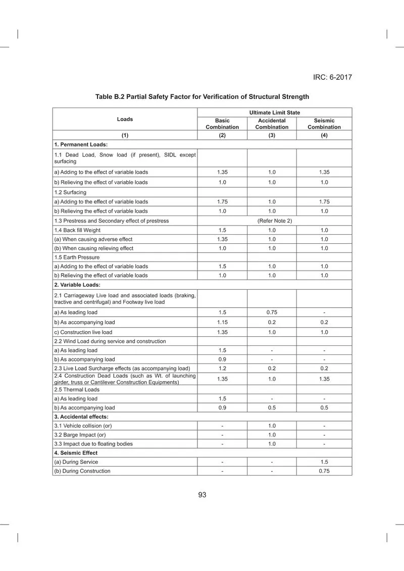
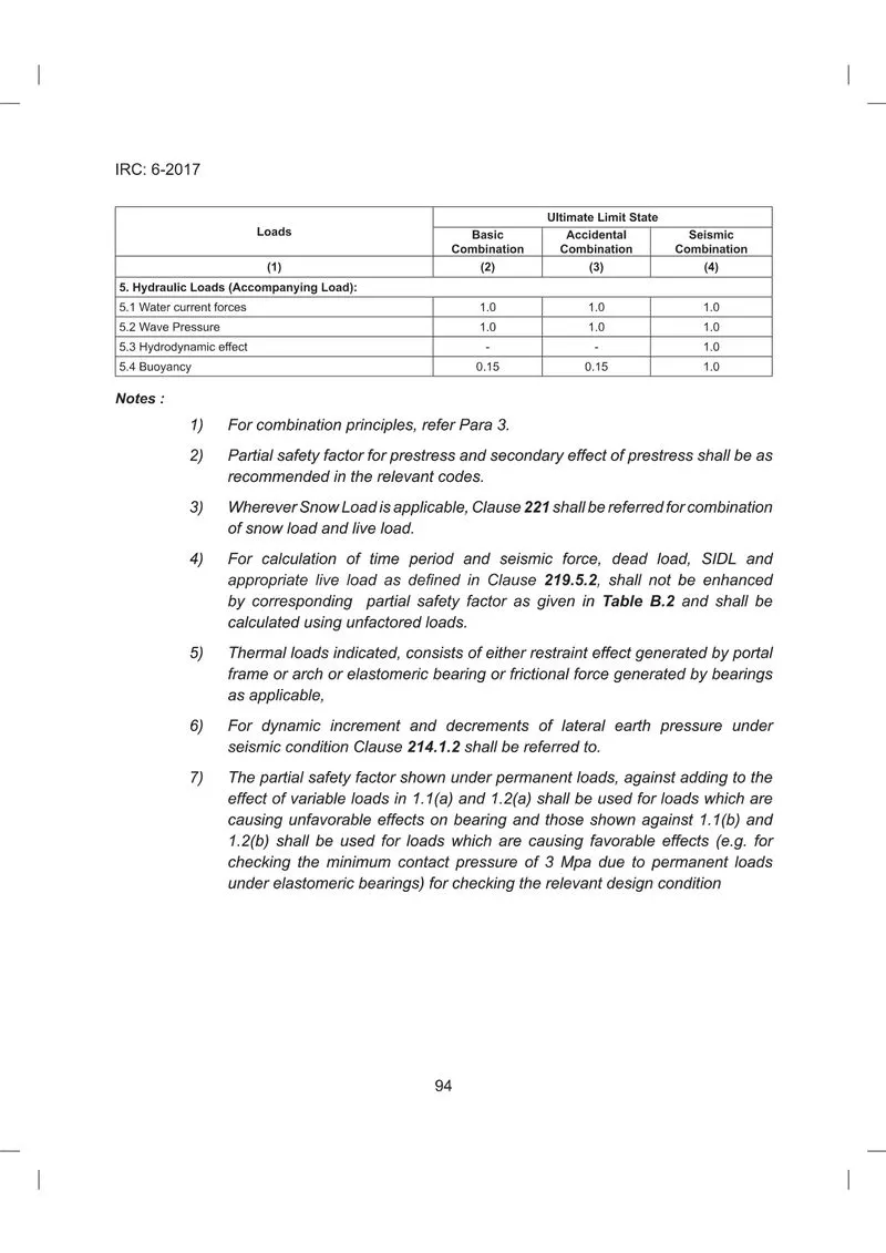
In limit state design, safety is expressed in terms of the probability that the structure will not become unfit for its intended function during its useful life that is the structure will not reach a limit state. The initial idea of referring to a single failure criterion has been replaced by the comprehensive concept of multiple limit states. With this concept the local or the overall behaviour in all stages – elastic, cracked, inelastic and ultimate – are considered. In the limit state approach, a structure is considered as well designed if it could be shown that the probability of any limit state being attained is substantially constant for all the component members and for the structure as a whole and that consequently, the latter process adequate and uniform structural safety. Due to the number of variables involved, a rational determination of the safety of a structure, based on probability theory is not yet practical in the design office. Partial safety factors are therefore introduced for each limit state and these consist of gm, reduction factor for characteristic strength of materials and gf, enhancement factors for characteristic loads on the structure.
Que ) Also mention shear checks ?
Ans ) Design verification or checks for shear is carried out at ultimate limit state of strength only. All the clause related to shear checks are mentioned in section 10 of IRC:112 ( Ultimate limit state of shear, punching shear and torsion ).
Que ) What is the difference in shear with/without reinforcement?
Ans ) Whenever the value of actual shear stress exceeds the permissible shear stress of the concrete used, the shear reinforcement must be provided.
The purpose of shear reinforcement is to prevent failure in shear, and to increase beam ductility and subsequently the likelihood of sudden failure will be reduced.
Shear reinforcement is required to prevent propagation of diagonal cracks. The diagonal tension cracks develop in the beam, when the strength of the beam in diagonal tension is less than the strength in flexural tension. On this type of failure, the cracks start to develop due to the flexure at mid-span.
For reinforced concrete beam without shear reinforcement, shear and punching can be the governing failure mode at the ultimate limit state if subjected to large concentrated loads.
Shear and punching of beam without shear reinforcement has been a challenging problem in assessment based on current standards.
Que ) How to check staining thickness and its steel ?
Ans ) The minimum thickness of well steining should be not less than 500mm and satisfy the following empirical formula.
h = k d √ l
Where h - Minimum thickness of steining in m
d - External diameter of circular well or dumb bell shaped well or in case of twin D wells dimensions in plan in m
l - Depth of well in m below the top of well cap or LWL whichever is more (for floating cassion, it is taken as depth of well in m below bed level)
k- a constant depending upon the type of soil and material of well
The value of k as outlined in IRC: 78-1983 for different types of wells are complied in Table 19.1
Stresses in steining shall be checked at critical points where tensile/compressive stresses are likely to be maximum. The stresses developed in the well steining at any level under various conditions of loading during sinking and service should be within safe permissible limits. For plain concrete wells, vertical reinforcement in the steining should be not less than 0.12 percent of the gross cross sectional area while for R.C.C. wells, the minimum vertical reinforcement distributed on both faces should be not less than 0.2 percent (Inner face - 0.06 and outer 0.14 percent) of the cross sectional area. The transverse reinforcement in the form of hoops should be not less than 0.04 percent of the volume per unit length of the steining.
Que) What will be the change in PCC and RCC steining.
Ans) Clause 708.3.3 For plain concrete wells (un cracked section), vertical reinforcements (whether mild steel or deformed bars) in the steining shall not be less than 0.12 percent of gross sectional area of the actual thickness provided. This shall be equally distributed on both faces of the steining. The vertical reinforcements shall be tied up with hoop steel not less than 0.04 percent of the volume per unit length of the steining.
Clause 708.3.4 In case where the well steining (Cracked section) is designed as a reinforced concrete element, it shall be considered as a column section subjected to combined axial load and bending. However, the amount of vertical reinforcement provided in the steining shall not be less than 0.2 percent (for either mild steel or deformed bars) of the actual gross sectional area of the steining. On the inner face, a minimum of 0.06 percent (of gross area) steel shall be provided. The transverse reinforcement in the steining shall be provided in accordance with the provisions for a column but in no case shall be less than 0.04 percent of the volume per unit length of the steining.
Que) How the spacing of pile is determined in 6 pile system. Describe the bulb theory with neat diagrams showing the stress distributions.
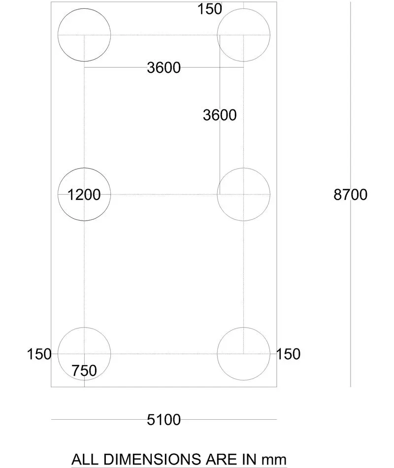
Ans) Generally kept 3 times diameter of circular piles as per IRC 78. Beyond this will be uneconomical. Capacity is the sum of individual capacities of pile group only if spaced in such a manner that there is no overlap of stress.
For 6 pile system of 1.2m dia of pile length in Transverse direction is 8.7m and longitudinal direction is 5.1m. Clause709.1.5.1 of IRC:78-2014
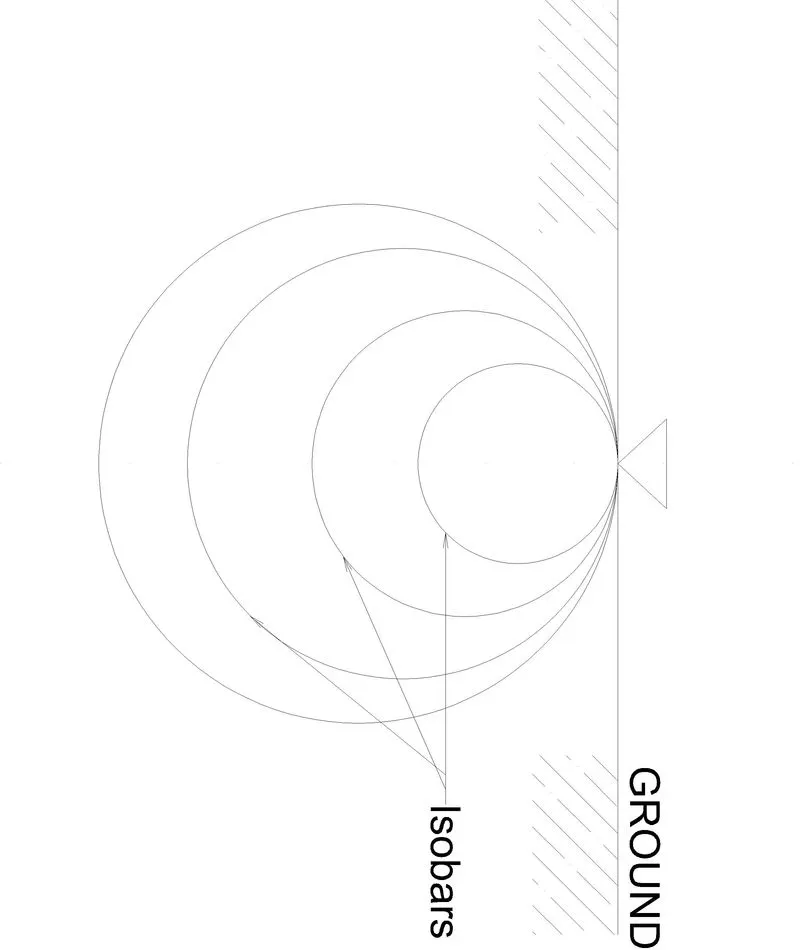
Pressure Bulb Theory – An isobar or pressure bulb is a stress contour or a line which connects all points below the ground surface at which the vertical pressure is the same. An isobar is a spatial curved surface and resembles a bulb in shape; this is because the vertical pressure at all points in a horizontal plane at equal radial distances from the load is the same. The stress isobar is also called the “pressure bulb”. The vertical pressure at each point on the pressure bulb is the same. Pressure at points inside the bulb are greater than that at a point on the surface of the bulb; and pressure at points outside the bulb are smaller than that value. Any number of pressure bulbs may be drawn for any applied load, since each one corresponds to an arbitrarily chosen value of stress. A system of isobars indicates in stress intensity from the inner to the outer ones and reminds one of an “Onion bulb” Hence the term “pressure bulb”. An isobar diagram, consisting of a system of isobars appears somewhat as shown in fig below.
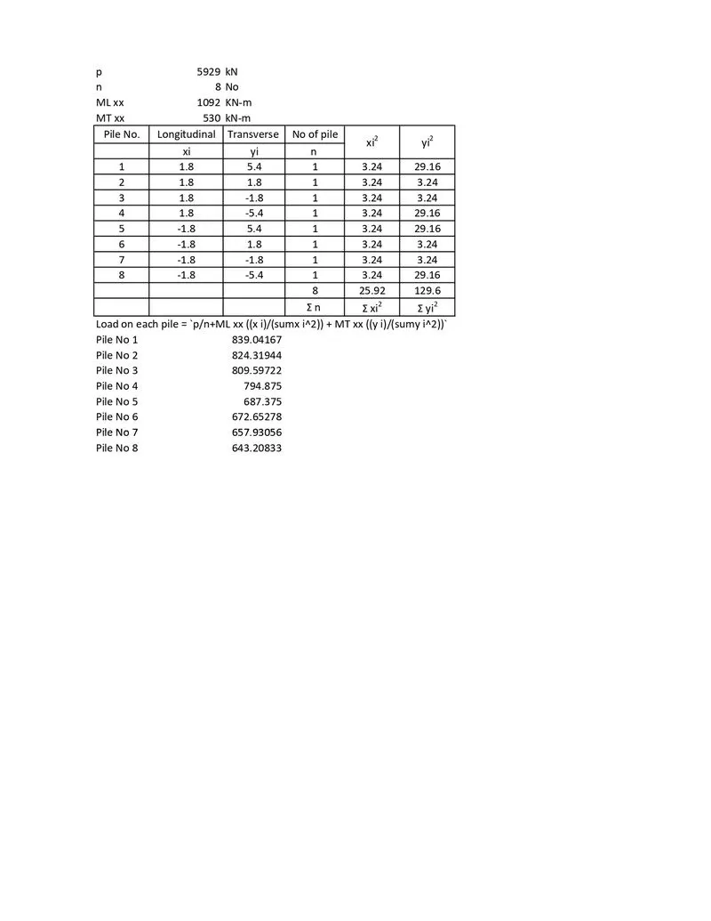
Que) To calculate the reaction exerted on the group of piles from the pier of the bridge.
Given Data - Total vertical reaction (P) = 5929 kN
Total moment about L-L axis (ML) = 1092 kN.m
A total moment about the T-T axis (MT) = 530 kN.m
Total horizontal force along L-L axis (HL) = 83kN
Total horizontal force along T-T axis (HT) = 172 kN
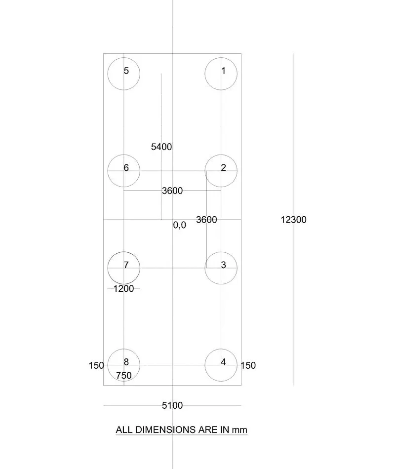
Assumption - Total no of piles (n) = 8 Nos.
Dia of Pile = 1.2 M
Distance between the p = 3.6 in both directions.
Offset on both ends = 150 mm.
Thank you !