Week 10 - Challenge 1- Attachment Feature Creation (Ribs & Screw Boss)
Attachment feature creation (Ribs and Screw Boss)
Aim:
To create the door handle component from the given class A surface.
To create a tooling axis for the given class A surface meeting the requirements of the class A Surface.
To attach B side features in the component
To perform the draft analysis on the model.
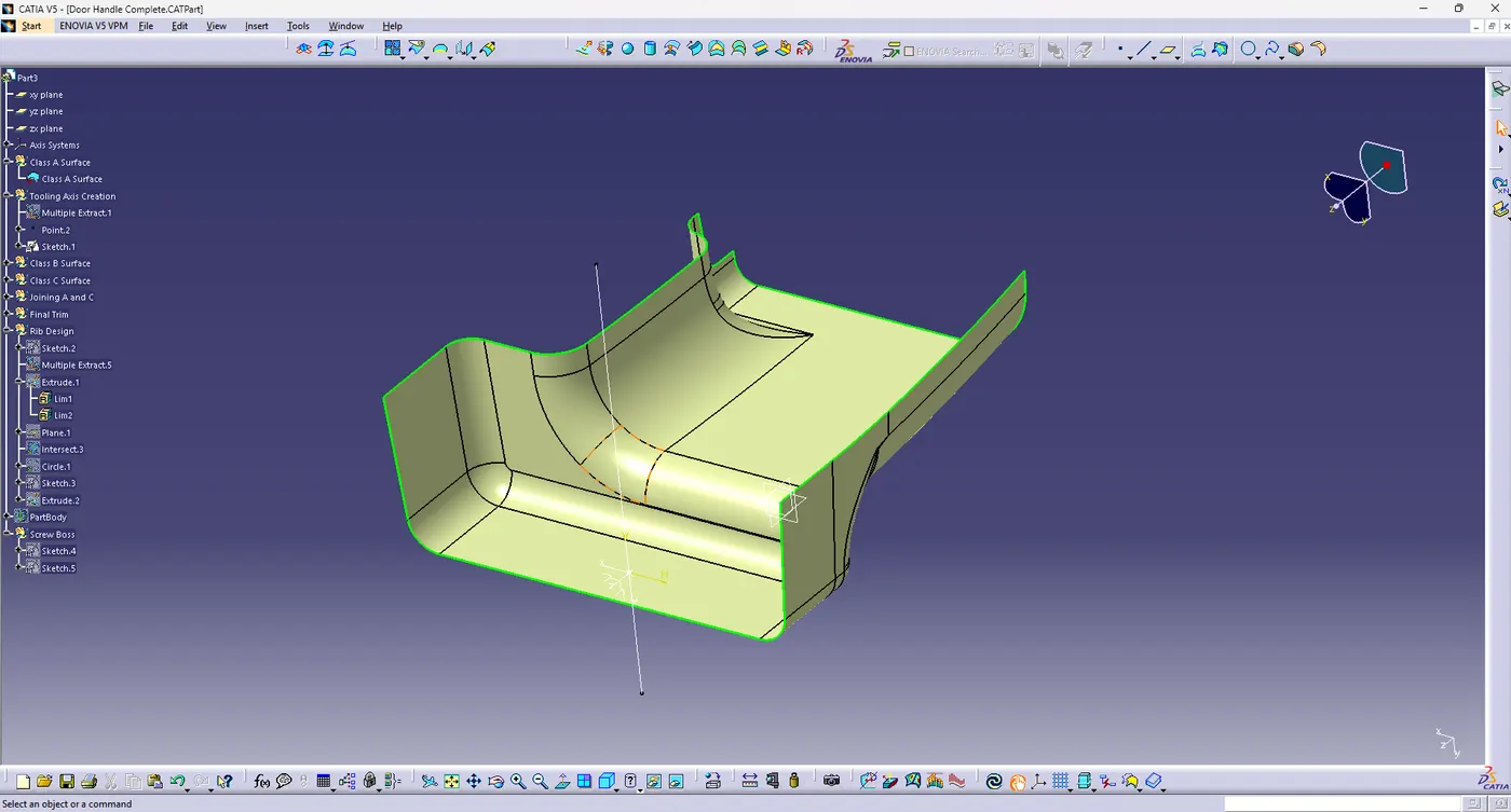
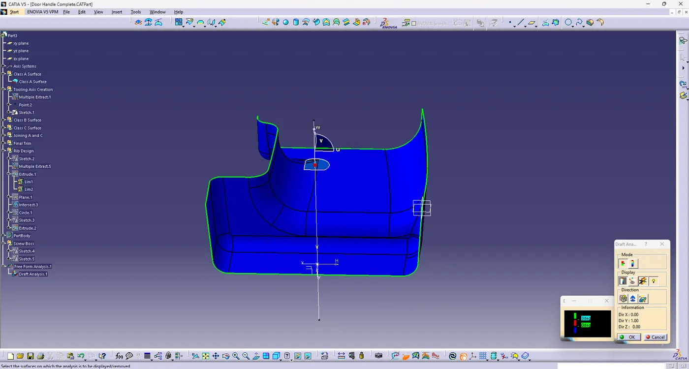
Creation of tooling axis:
1. The tooling axis is the direction that the mold pulls a part. The mold is built in two separate pieces, basically the core side and the cavity side. The core pulls apart from the cavity and that's the die line or the tooling axis.
2. Open the CATIA V5
3. Check for the gaps between the surfaces for that click on the join feature.
4. If there is any gap between the surfaces join them with a maximum tolerance of 0.003mm
5. Now extract the flat surface and then create a point in the center of the surface and use the point and direction method of creating line for the tooling axis.
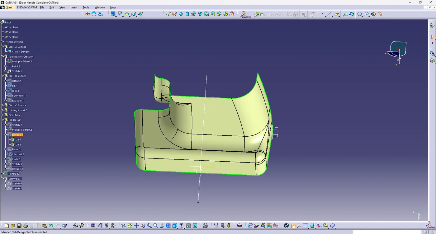
Creating Class B Surface:
1. Extract the surfaces from the Class A using multiple extract and then untrim them.
2.Use Extrapolate to make sure that all the untrims are properly intersected to trim and offset the surfaces to 2.5 mm to create the thickness.
3. Trim the extra surface using the trim command.
4. Insert them into a new geometrical set and name it with respective part names.
5. Apply fillets to the model after creating the entire surface.
6. If the edges are outside the fillet value will be added to the thickness of the component. and if the edges are inside the fillet value is subtracted from the thickness of the component. For example: If the thickness of the component is 2.5 mm and the fillet value is 15mm, So the outside portion value should be 17.5mm and inner edges should be filtered 12.5 mm to get uniform thickness.
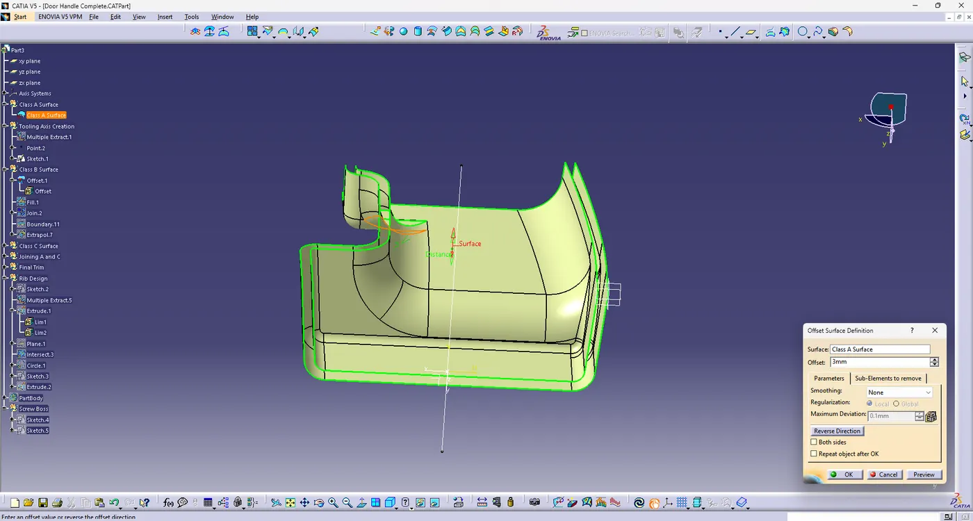
7. Then the edges of the B surface are bit more extrapolated so that it can can be trimmed of later with the joining of A and C surface.
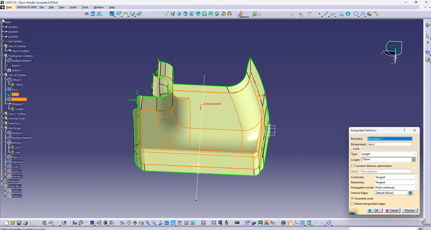
Creation of class C surface:
1. Extract the boundary of the class A Surface using boundary surface.
2.Use Sweep Command profile type line> subtype as with draft direction>chose the guide curve and draft direction>give the draft direction>preview.
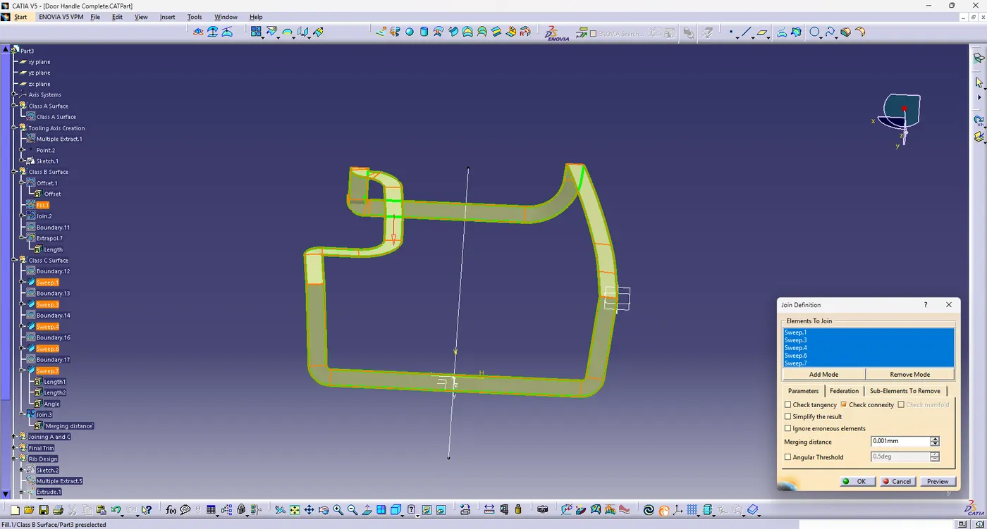
3. Then once the class C surface created then trim it to make class c as continuous one surface
Joining class A and class C Surface:
Once the class C surface is created then add the class A and class C surface as one combined surface.
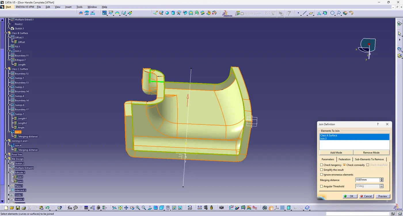
After joining the surface then trim the class B Surface with the joined A and C surface to create a closed surface.
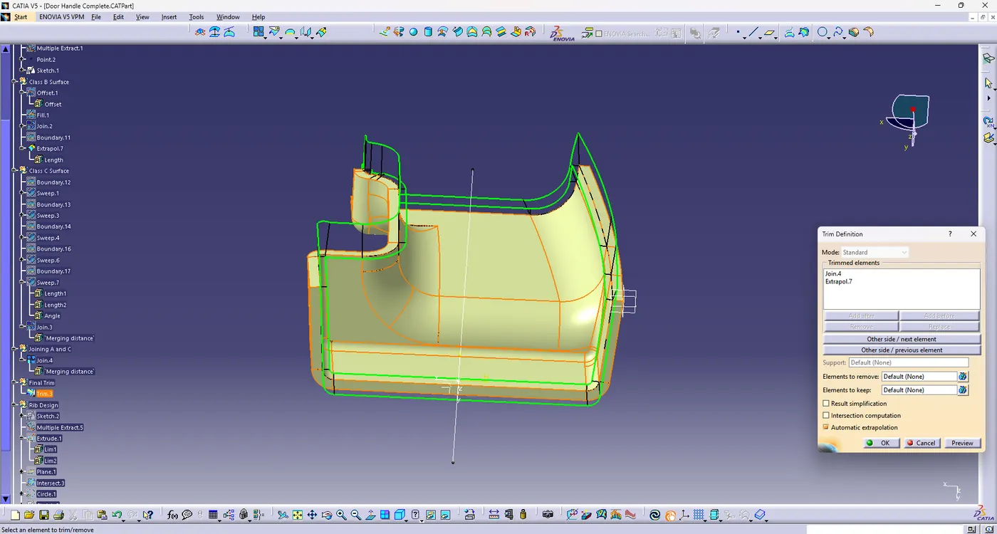
Once a closed surface is formed then create a part body by using the closed surface from the part workbench.
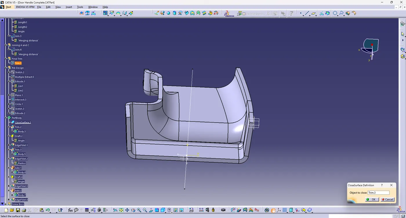
Rib and Screw Boss Design
Rib Creation:
Rib is a feature which provides stiffness and strength to the modelled parts.
They are thin extensions that run perpendicular from a wall or a plane.
They provide these features without increasing the thickness of the overall part.
If the wall is too thick, warping and sinking can result so that the entire design may need to be rejected.
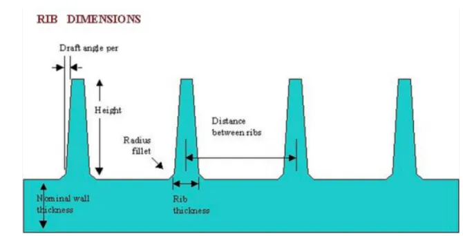
Design Principle for rib creation:
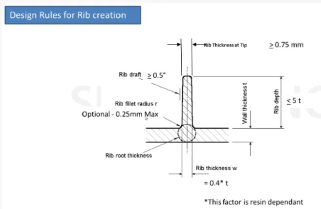
Taller ribs provide great support, rib height might approximately taken as 5 times the base thickness.
For all wall thickness less than 1mm , the rib thickness is same as the wall thickness.
A draft of 0.5 degrees per side is the minimum limit.
Rib thickness can be taken as 0.4 times the base thickness.
Minimum thickness at the rib tip is 0.75mm
optimum rib fillet radius can be taken as 0.25mm which is optional.
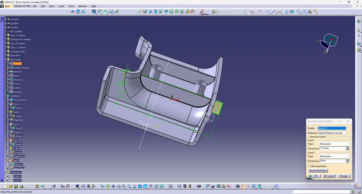
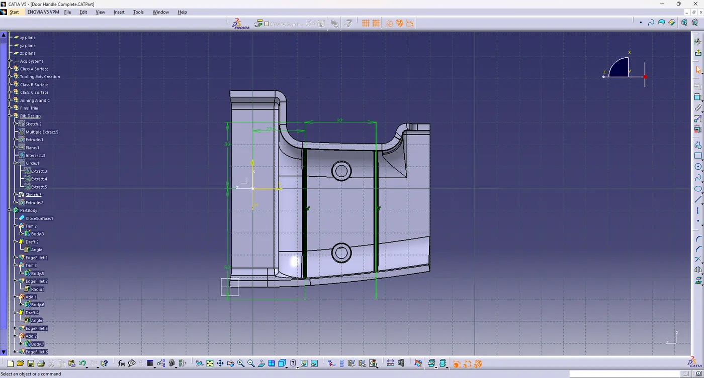
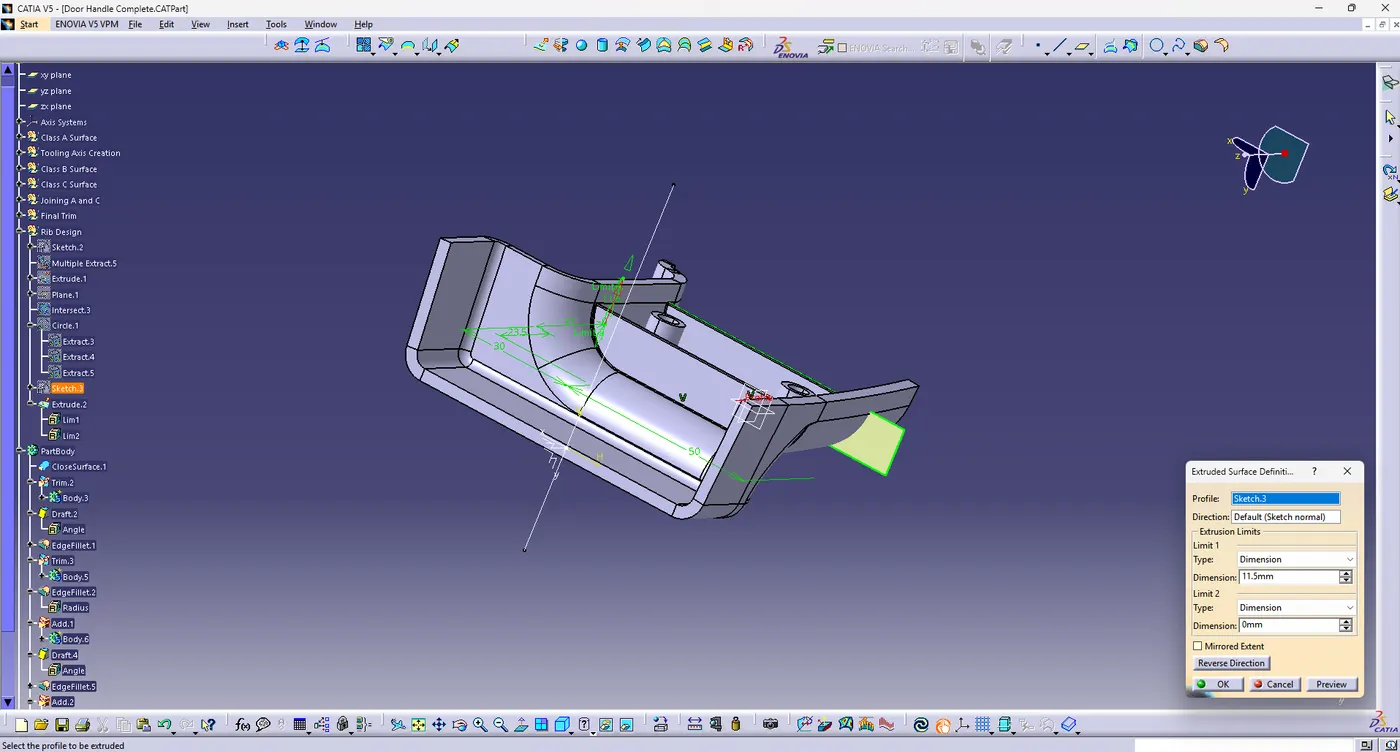
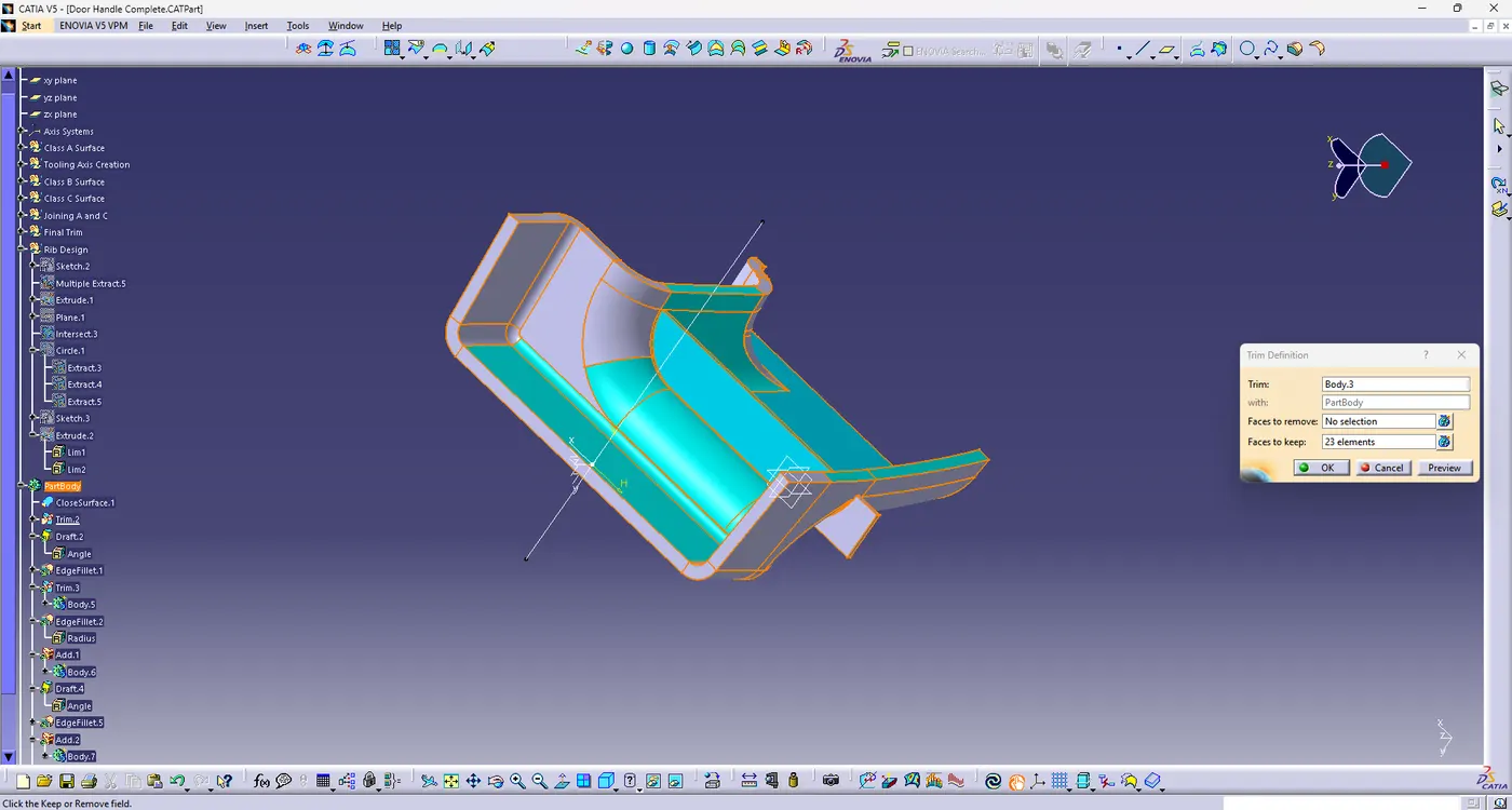
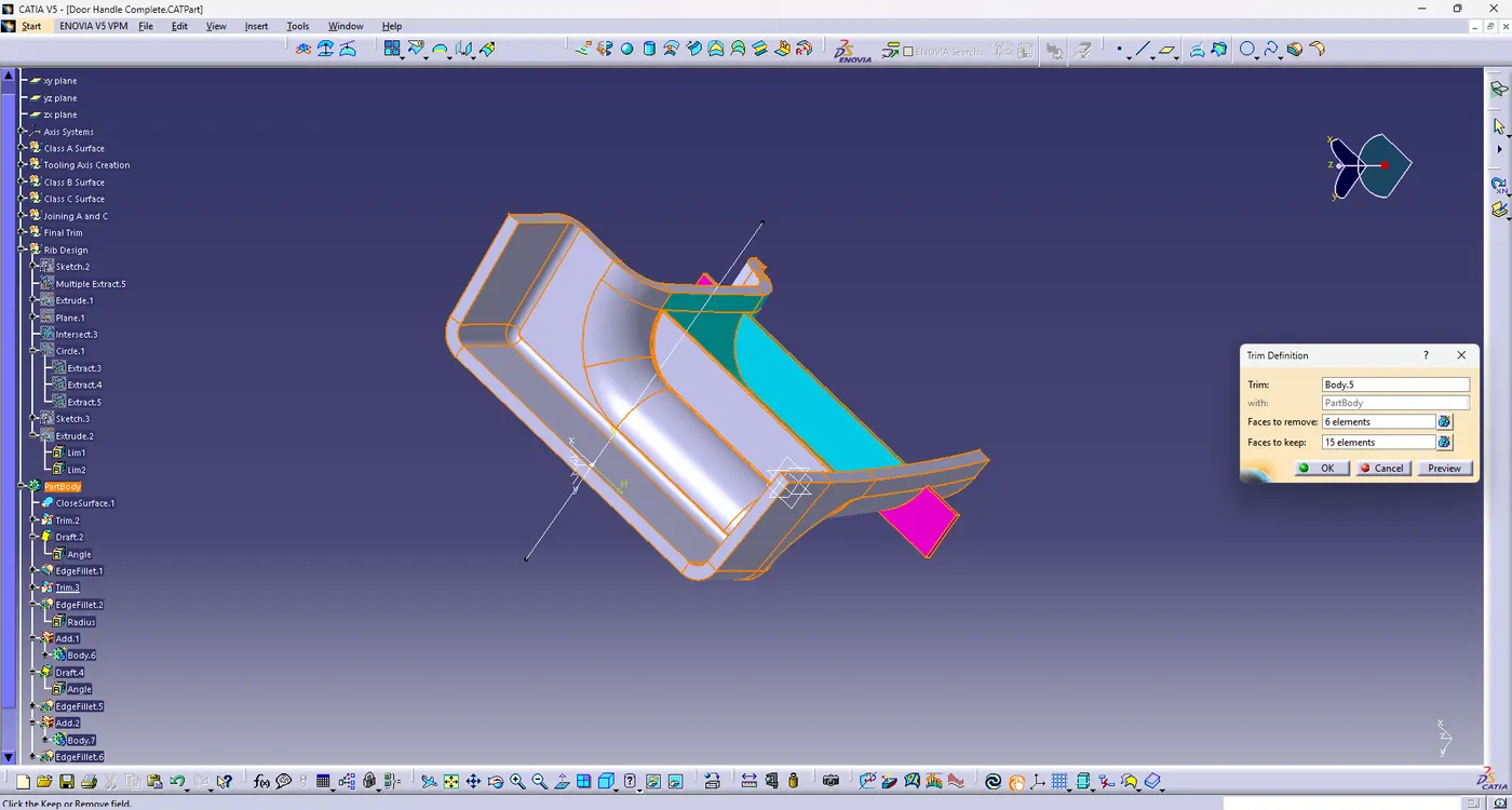
Screw Boss Design:
Bosses are commonly used for attachment and assembly of plastic components
They are used to aid in the assembly of molded parts by providing a channel for the screw.
Bosses must not merge into side walls as they may lead to formation of sinks.
Open Bosses can be used near a standing wall.
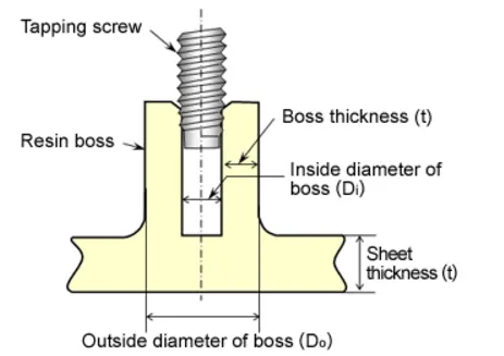
Design principle for the Screw Boss Creation:
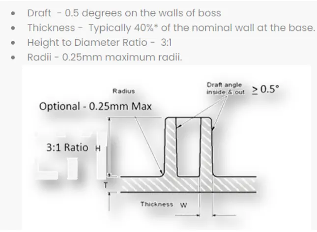
The boss thickness can be taken as 0.4 times the thickness of the component.
A Draft of 0.5 degrees per side is the maximum limit.
Height to diameter ratio must be 3:1
Optimum fillet radius can be taken as 0.25 mm which is optional
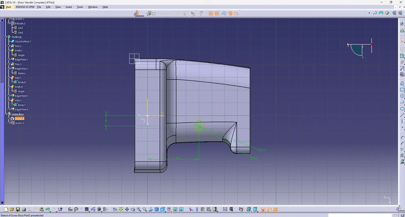
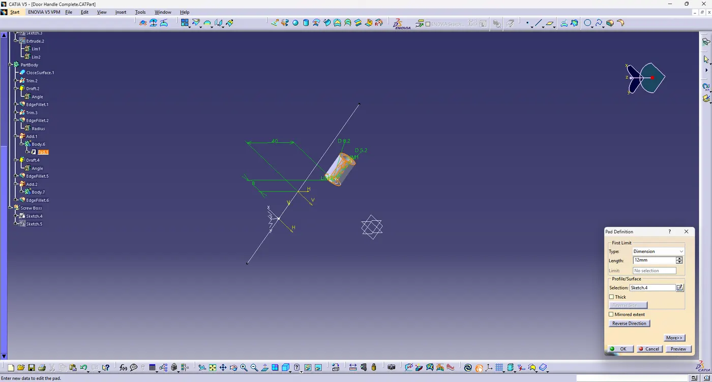
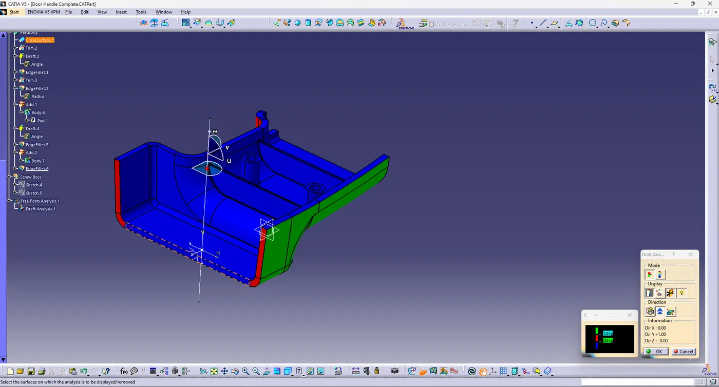
Conclusion:
The tooling axis and the solid CAT part with B side features is created from the given class A surface and draft analysis is performed.