Week 10 - Challenge 1- Attachment Feature Creation (Ribs & Screw Boss)
Objective: 1) Creating a solid feature from the given Class A surface
2) Creating the features like Ribs & Screw Boss as per given guidelines
Drill Handle Class A to Class C:
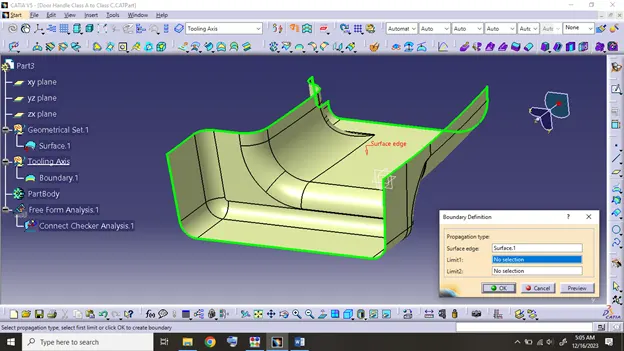
Step1: Insert a new geometrical Set to create a tooling axis. Before creating the tooling axis we need to check whether the given Class A surface is smooth & uniform. To do so we use the ‘Boundary Command’. As seen in the image below the boundary is continuous and no separate point is seen.
Step2: Now we create a dummy tooling axis to carryout draft analysis. To create this axis we use the bisecting line method.
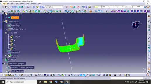
Now that we have done the draft analysis and we can see that all Class A surfaces are getting cleared we can move forward to create the Class B and Class C surfaces and finally the solid part.
Step 3: Next insert a geometrical set with the name class B surface. To do this we use the “Offset Command”.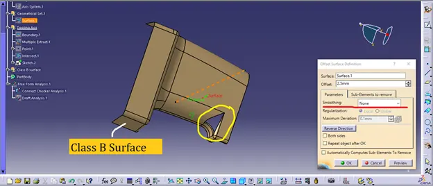
When we offset the Class A Surface with a distance of 2.5mm, some surfaces are missing in the created offset. As seen in the Dialogue box of the Offset Command, the smoothing option has a ‘None’ selection.
When changing this setting of Smoothing to ‘Automatic’ proper Class B surface is created as seen in the following images.
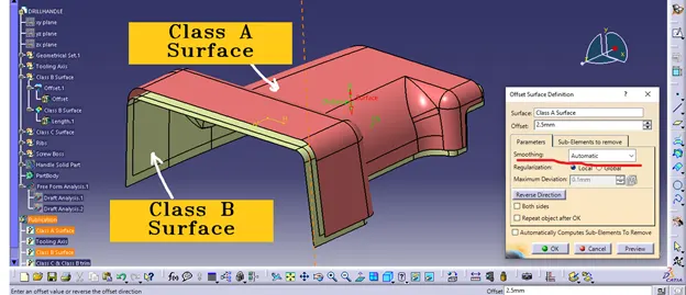
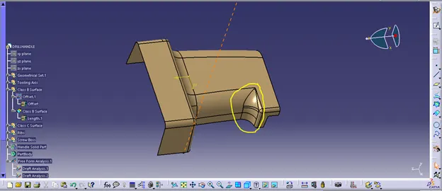
This method of ‘Smoothing’ the Offset saves us the time of creating a ‘Multi-Section Surface’ or creating the surface using the ‘Extract and Trim’ commands.
Step 4: Now we insert another Geometrical Set for the Class C surface. For creating the Class C surface we use the ‘Sweep’ command. We use the ‘Line with Draft Direction’ profile type while creating the C Surface.
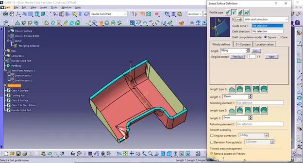
As seen above image the Cyan color surface is perpendicular to the tooling axis, hence it requires no draft and we can sweep these surfaces with the help of edges from class A surface at a 90° angle to the tooling axis.
The other surfaces which are in yellow are parallel to the tooling axis hence need to be given a draft of a minimum 3° with the tooling axis.
Next, we trim it with the Class B surface which needs to be extrapolated as per requirement to create the combination of Class B and Class C surface as shown in the following image.
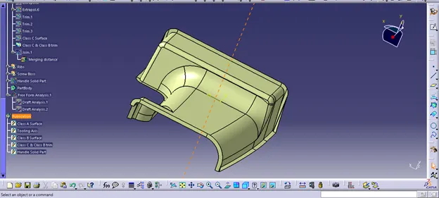
Now the final Join is done between the above surface & given Class A surface to create the closed surface of the required product.
Once we create the closed surface we change the workbench to Mechanical Part Design.
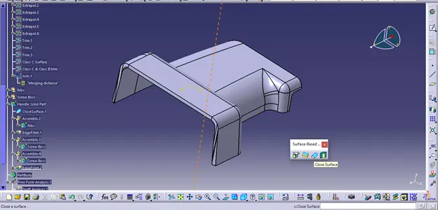
We use the ‘Closed Surface Feature’ from Surface-Based Feature to create the solid part file.
Till now we have created the basic Solid model from the given Class A surface. Next we will create the reinforcement features like Ribs & Screw Bosses as per requirement.
Ribs Creation:
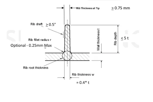
Standard rules for rib creation were followed to create the required ribs.
Step 1: To create the Ribs we extracted the surface on which the ribs will be resting. Next, we sketched the lines as per the required length and changed them to ‘Output feature’ for ease of visibility and usage after exiting the Sketch workbench.
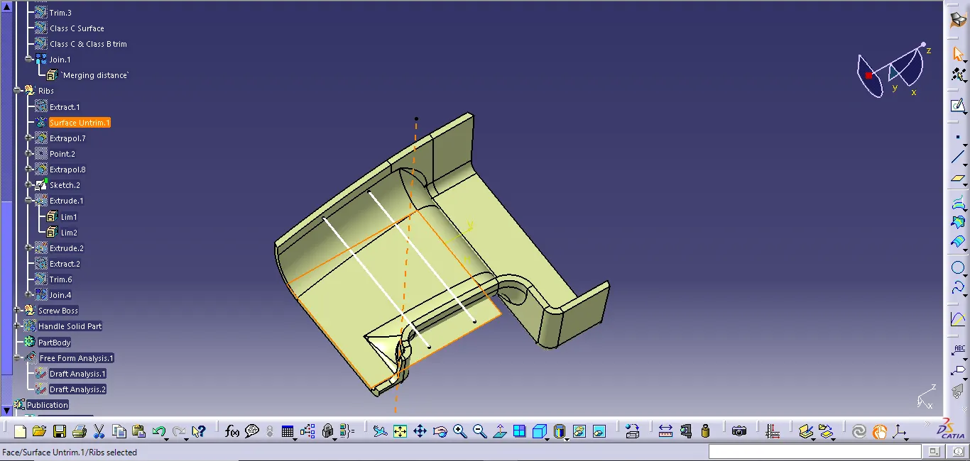
Step 2: No we extrude the above two lines to a height which is equal to ‘5t’ i.e. five times the wall thickness of the main body. In our model it is “5x2.5=12.5mm” Hence we use the ‘Extrude’ command to create the surface for the rib.
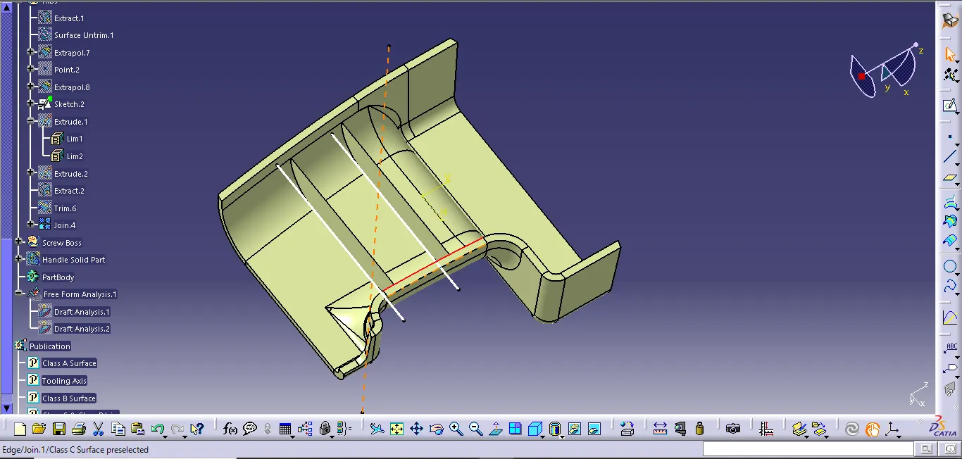
Step 3: Now we use the “Join, Trim” commands to create the resultant surface for the ribs. Next, we switch to ‘Part Workbench’ and by inserting a ‘Body’ we use Thicken profile with a neutral element to create the solid Ribs.
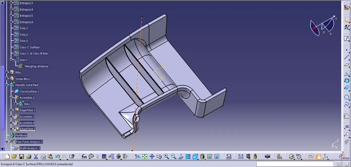
Step 4: The last step is to ‘Assemble’ the above-created ribs into the Main body.
Step 5: Once the Ribs are assembled into the main body we provide a draft of 0.5° to the faces parallel to the tooling axis. After giving drafts to both the ribs we provide a fillet of 0.25mm to all edges of the ribs for a smooth molding process.
Screw Boss Creation
Step 1: Once the ribs are created we can move on to the creation of ‘Screw Boss’. As we can see in the following image attached we have all the required dimensional rules for the creation of Screw Boss. Now we insert a separate Geometrical Set for the Screw Boss. To create the Screw Bosses we use the ‘Extract’ command to extract the flat surface which supports the sketch of the Screw Bosses.
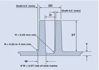
Step 2: The thickness of the screw boss as per the above-given guidelines has to be “0.6T” i.e. 0.6 times the wall thickness. For our model, we have assumed a 6mm screw for which we will have a hole size of 5.2mm.
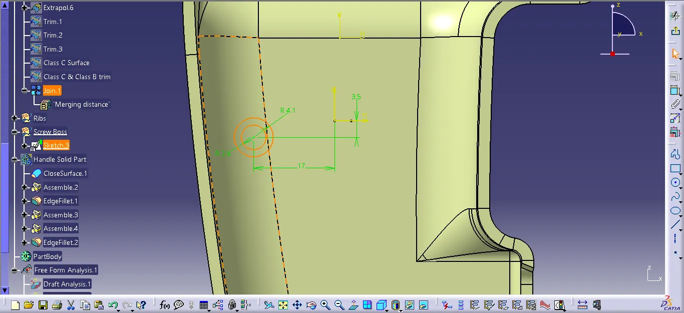
Step 3: Once the sketch is done we add a body and then pad the sketch to 7.5mm height which is 3 times the wall thickness. Once the pad is done last step is to provide a draft for the same with a 0.5 degree.
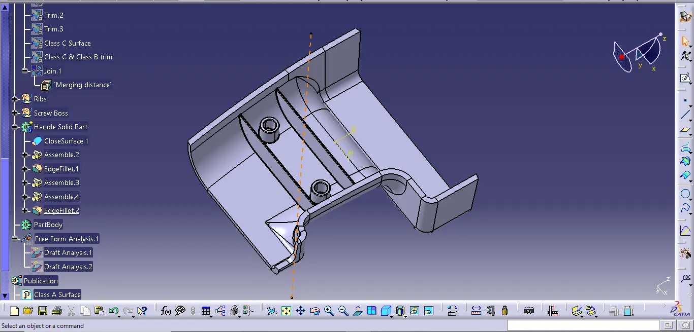
Step 4: The next step is where we translate the above feature to a suitable distance and finally we assemble the screw boss to the main handle body.
The last step is to perform a draft analysis on the created solid part.
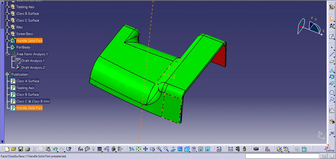
As seen in the above image we can see that the solid body is following the draft rules for plastic feature.
Conclusion: This is how we have created a part from the given Class A Surface with reinforcement and assembly features such as Ribs and Screw Boss.