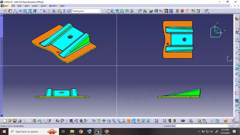
Week 9 - Challenge 1 - Base Bracket Design
Aim:
Create the Base Bracket Plastic component through the given Class-A surface. To begin with, the tooling axis for the given Class-A Surface should be created meeting the requirements of the draft angle and at the end perform the Draft analysis on the model.
Thickness of Plastic Part - 2.5 mm
Input: Class A Surface model
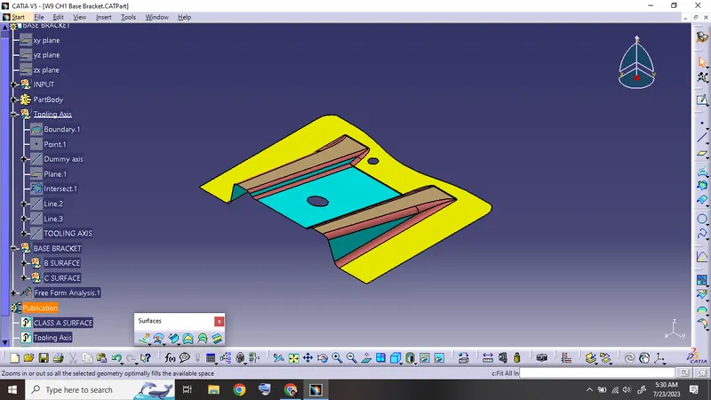
Before starting the design for creating surface B and surface C from the given surface A model, it is vital to perform 2 operations viz.,
1. Checking the continuity of the given surface model
2. Defining the Tooling Axis
3. Performing the Draft Analysis
Continuity Check: This is a very important step to carry out before starting to work on the given surface model as it is the input for complete part design. To check the continuity of a given Class A Surface model we use the boundary tool. In the current example of Base Bracket the given class A model has got continuity as shown in the image below
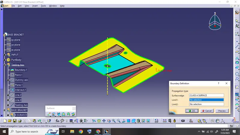
Tooling Axis: It is the axis along which the cavity part moves when the part is being moulded. It is very important to clear maximum inclined surfaces/ surfaces with drafts, holes and flat surfaces along this axis to reduce the tooling cost and avoid the usage of side cores/multiple cores that are inclined to the main tooling axis.
Steps to define the tooling axis using Bisecting method:
1. Out of the 3 axes viz, X axis, Y axis, Z axis check whether the maximum number of holes and inclined surfaces are perpendicular to the axis. In the case of this example of Base Bracket, the inlined surfaces i.e. the Ribs 1& 2 are at a certain angle to the Z axis. Also, the 2 holes and the base flat surface are perpendicular to the Z axis too.
2. The next step is to choose the plane along which we will place the tooling axis. To do this we need to take the plane that intersects the maximum number of inclined surfaces and holes. In the current example, it can be seen that the YZ plane satisfies our requirements.
3. Once the plane is identified the next step in tooling axis defining is to take the intersection sketch of the given sample to get the profile of all flat, inclined surfaces and holes. While doing this we need to define a dummy tooling axis too. This helps to define the actual tooling axis. As seen in the image below we have placed the dummy tooling axis and the intersection plane at the hole on the inclined surface in between the 2 ribs.
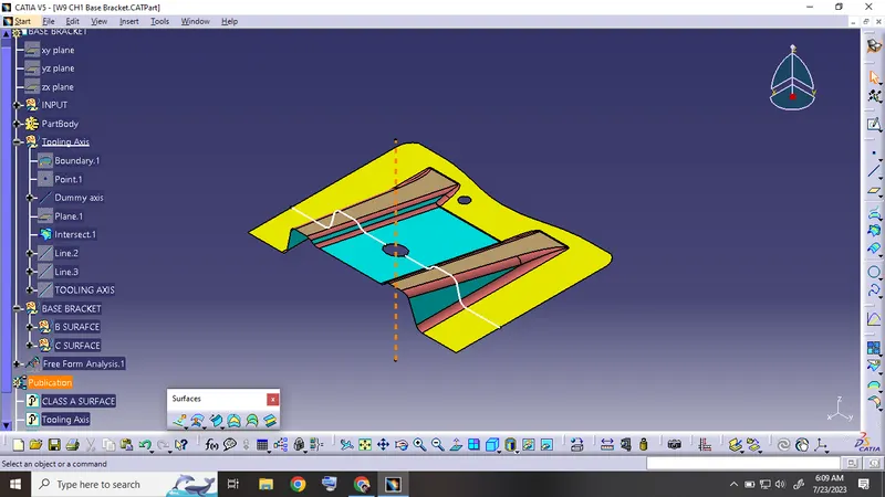
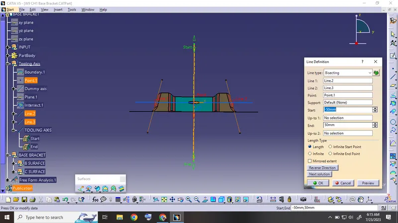
4. Using the inclined surface projections from the intersection sketch we can define the Main tooling axis with the help of a Bisecting line as shown in the following image. This ensures the creation of the right tooling axis at the desired location.
Once the tooling axis is defined we need to carry out the draft analysis for the given Class A part. In plastic moulding, it is essential that the moulded parts have walls with certain drafts(inclination) instead of perfectly perpendicular to the base. These drafts ensure the easy ejection of moulded parts with the best surface finish.
Steps in draft analysis:
1. The most important step while starting the draft analysis is to change the Material View mode to Custom View mode.
2. Next click on the Feature Draft Analysis from the analysis tab. The dialogue box of draft analysis occurs where you need to select the surface for draft analysis.
3. The next step is to align the compass with the tooling axis. Sometimes the compass gets aligned in an inverted position which may cause the result of the draft analysis to be in the negative zone(blue-coloured complete part-as shown in the image below). To overcome this issue you can use the invert option from the feature draft analysis dialogue box.
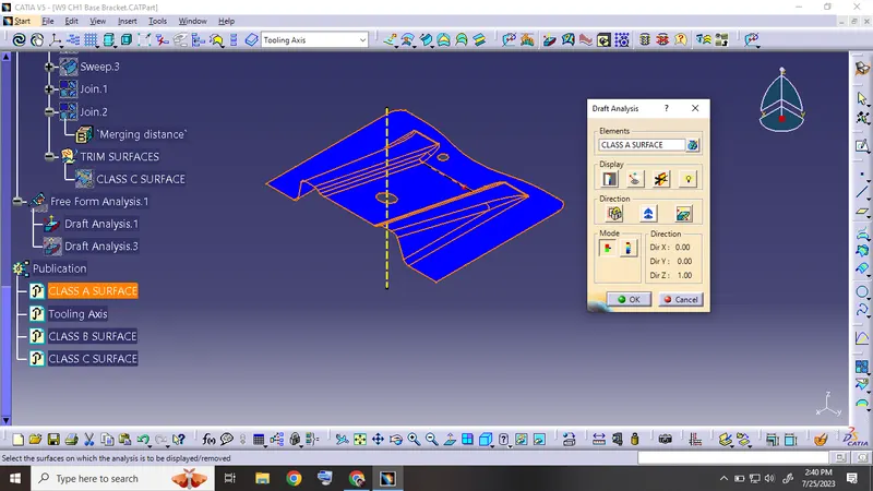
As seen in the above image the complete Class A surface is seen to be completely covered in blue color. You need to kill on the tab of "INVERSE DRAFT DIRECTION" as shown in the image below.
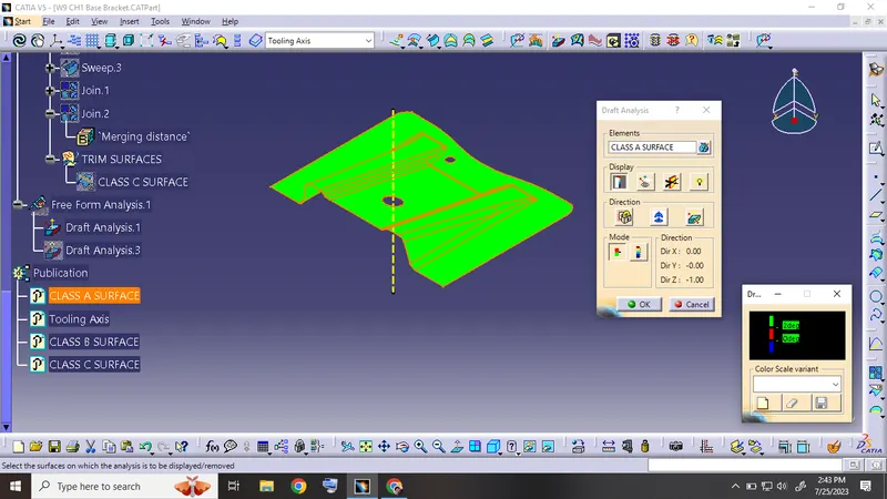
4. Once you ensure that the inclined surfaces are within the specified range of draft you can start to create the Class B part from the given Class A Surface.
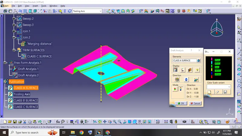
Draft analysis of Class A Surface
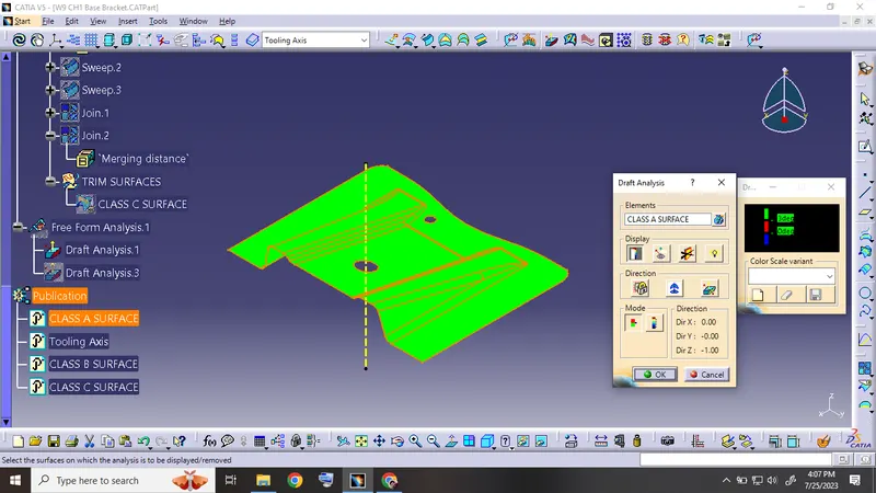
Image of colour scale variant of Class A Surface:
Draft analysis of Class C Surface:
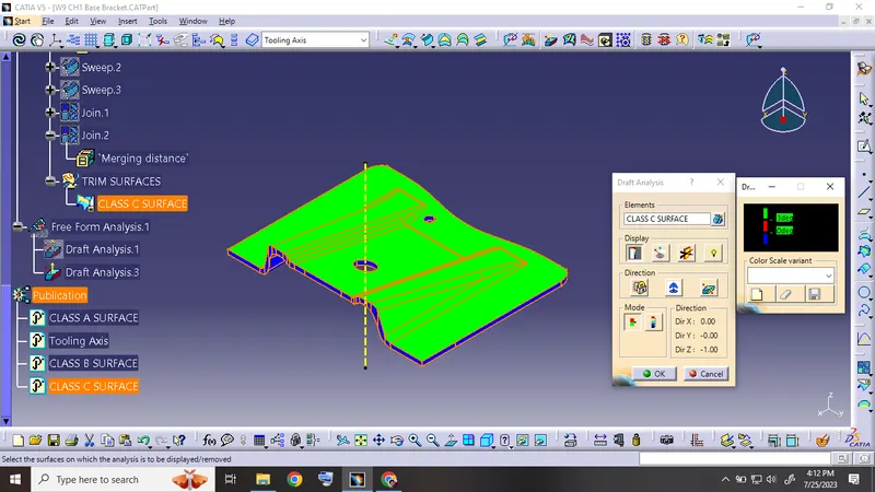
Image of colour scale variant of Class C Surface:
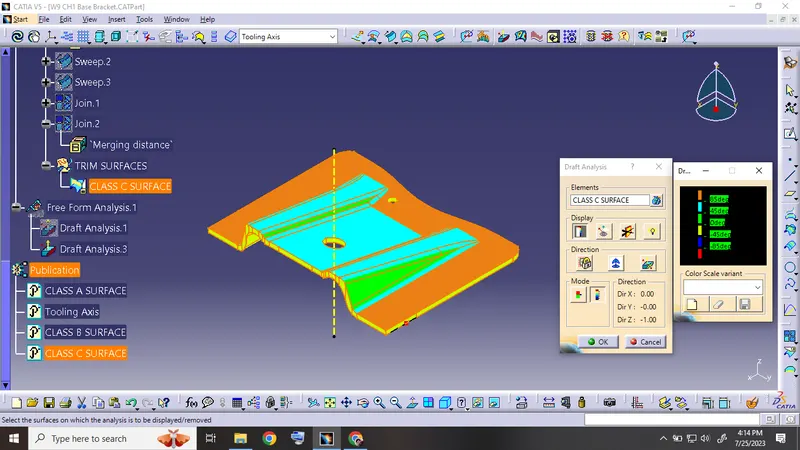
Following are the images of the completed plastic surface with colour shades for draft angle: