Week 9 - Challenge 2 - Switch Bezel Design
Objective:
- Create the Switch Bezel Plastic component through the given Class-A surface.
- Perform Draft Analysis of given Class A surface and Designed Class C Surface.
Given class A surface:
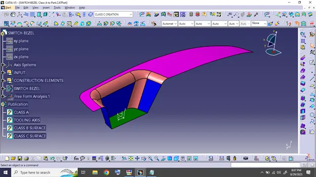
Procedure:
- Initially, using the boundary command, you must check whether the given Class A surface model is smooth and uniform. If any irregularities are found in Class A they can be solved with the help of commands like Multiple Extract, Trim, Extrapolate, Join,
- The next step is the creation of the tooling axis.
When Creating the tooling axis for the given part we need to consider the direction of release of part from the Core and Cavity. For a Switch Bezel, the best direction for the tooling axis will be the one clearing the pocket in the perpendicular direction to its base. Following are the steps.
a. We extracted the base of the pocket in the switch bezel and located a centre point of the extracted surface. We inserted an axis system at this centre point.
b. The next step is to use the intersection command at the yz plane of the newly created axis system and then draw two inclined lines in the positioned sketch. We draw a bisecting line with the help of these two lines.
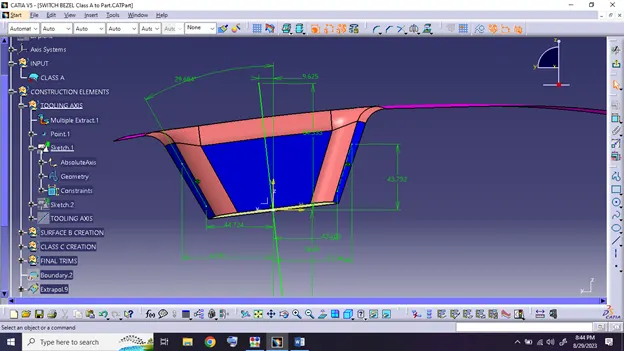
<!--[endif]-->
The below image shows the bisecting line
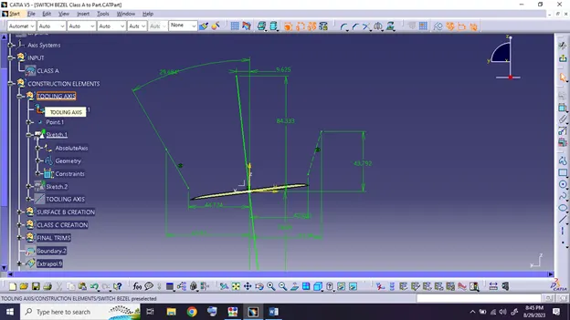
c. Similarly with the use of the intersection command along the xz plane we create another positioned sketch where we have only one inclined line. So we use the previously created center point to draw a line and give an inclination of 4 degrees tentatively.
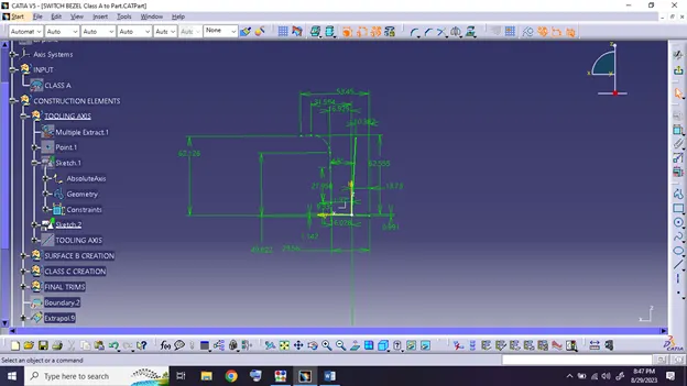
<!--[endif]-->
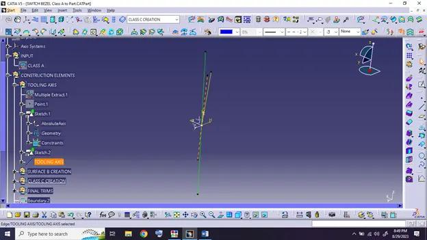
d. Then we draw a bisecting line using the above created two lines which will be used as the tooling axis for the switch bezel (the orange dotted line is the tooling axis)
<!--[endif]-->
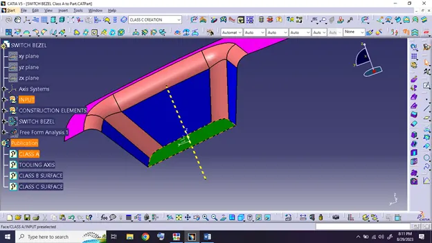
Now that we have created the tooling axis, we can start with creating the class B and class C surfaces, respectively.
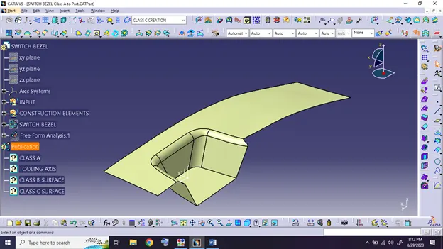
Class B surface:
 '
'
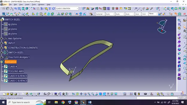
Class C Surface:
Draft Analysis:
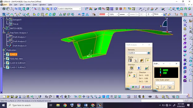
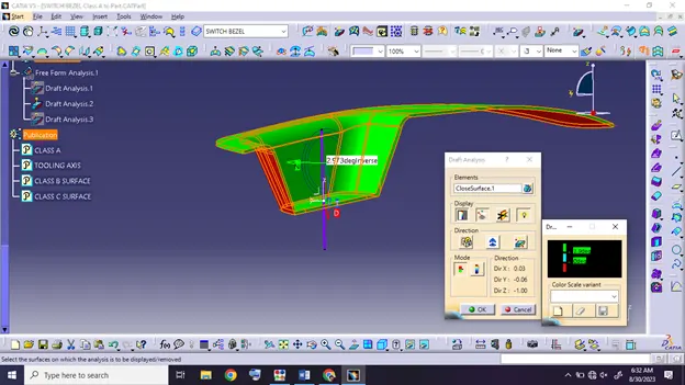
It is important to carry out the draft analysis of both the class A model and the final solid body to ensure that the designed part is manufacturable or not.
For both types of surfaces, we have the same procedure as follows
- Change the view mode to Material Mode.
- Next, Select the Feature Draft Analysis Tool to perform the operation.
- Click on the compass icon, move it to the tooling axis and align it with the tooling axis.
- Once aligned you must lock the draft direction view.
- The Draft scale will show color variants based on the defined angle for the draft
- In case you want to find out the draft at a particular point you can check it with the help of the Analyze Under Running Point button in the dialogue box.
Class A Draft Analysis
<!--[endif]-->
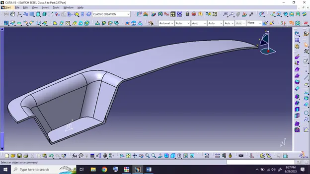
Final Solid Body & its Draft Analysis:
<!--[endif]-->
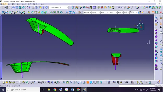
Following is the image with all views:
<!--[endif]-->
Please find the attached file of the designed plastic part.