Week 10 - Challenge 1- Attachment Feature Creation (Ribs & Screw Boss)
Aim :- Create the rib for the Drill Handle considering the design rules.
Given Class A surface of door handle with the thickness of the component 2.5 mm.
DRAFT: It is the degree of taper that is incorporated into the side wall and cores of the die cast tool to aid in the removal of a part. Primarily, they function to reduce the friction between the part and the tool as it is ejected. Without draft angles, parts can be stripped, dented, or get stuck in the tool.
The Draft Analysis command enables you to detect if the part you drafted will be easily removed. In the case of plastic injection molded parts it also allows the designer to see if there is enough draft on the part to ensure that it can be correctly grained.
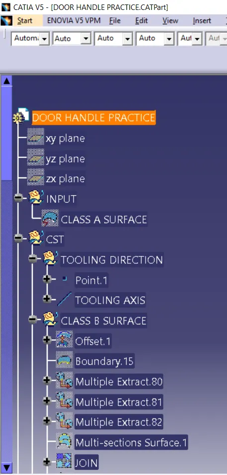
TOOLING AXIS CREATION:Tooling axis is the direction that the mold pulls apart. It is necessary to create a tooling axis to give draft to the component.. For the given Class A surface, the best tooling direction for the component is chosen by considering the tooling of the final product. It is chosen in such a way that the component is cleared with minimum tooling.
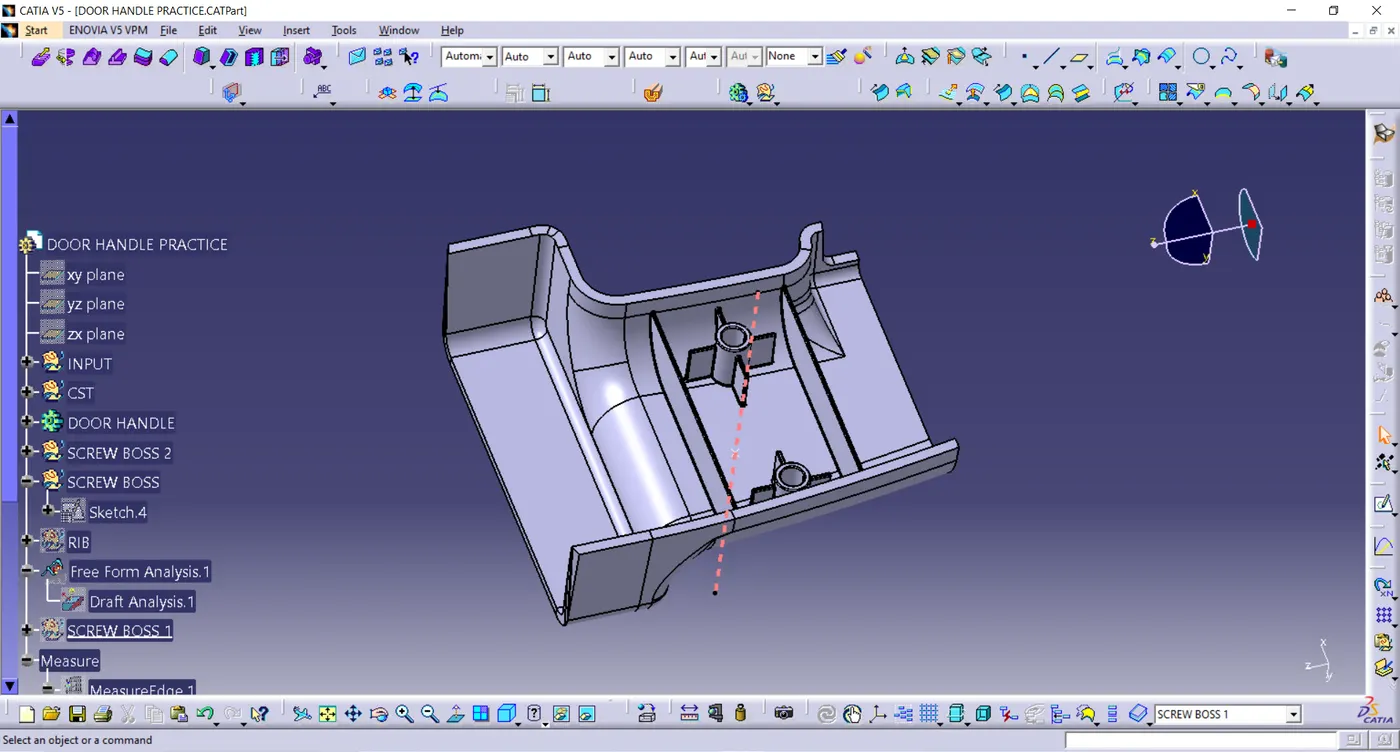
Class B Surface :- The surface which is back side of Class A surface is called Class B Surface. Mostly it not visible. It is created with the help of Class A surface with some distance (thickness)2.5 mm .
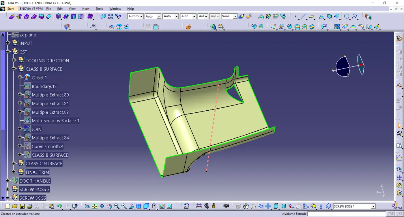
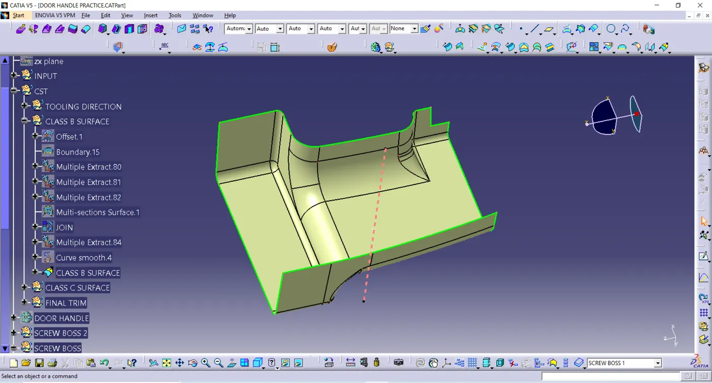
There is one gap in B surface when offset it for 2.5 mm . The gap is fill using of boundary command and fill command and join with the B ssurface .
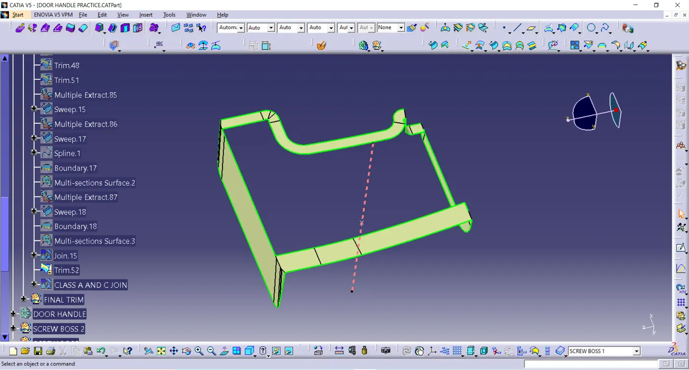
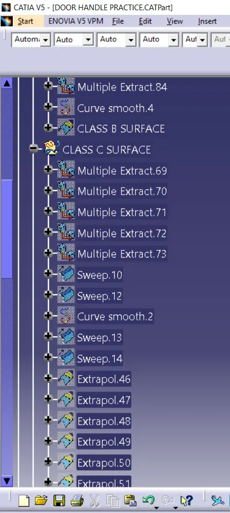
CLASS C SURFACE:-Surface that joins class-A and class-B surfaces is class-C surface. Class C is often specified for interior surfaces not readily visible, surfaces that will be covered by another part when assembledSince it is a complex class-A surface, we cannot simply create the class-A boundary curve and sweep it at one shot. Hence, we need to create smaller curves using multi-extract command and then create sweep of 90 degree with reference to the surface option. sweeps at the midportion of the bumper should have a 93 degree value to pass the draft analysis.
The Class C surface is the back side of a part of a surface that is permanently covered by another part.With the help of join and trim feature I have created a closed surface body.
Class C surface generally connects the Class-B surface to the Class A surface.Referring to the below pic, Class-C Surface is shown.for creating a Class -C surface used the following command:
- Boundary: pick the boundary for the next operation.
- Swept: swept the selected boundary .
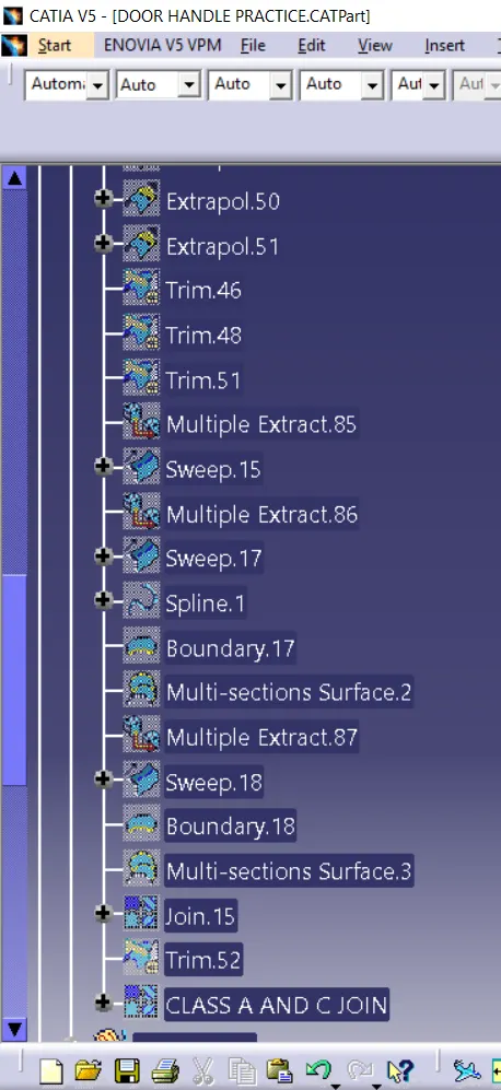
- Extrapolate: surface can't join properly, so I used to extrapolate those surfaces.
- Trim: trim those extrapolate surfaces and get a required surface.
- Join: now join those surfaces with each other and form a single surface.
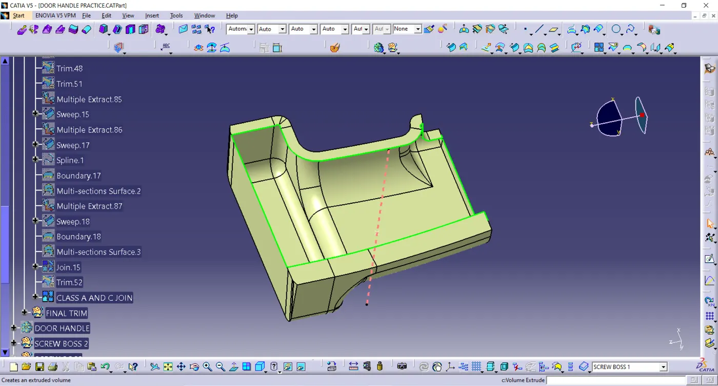
Final Trim :-
Now the class – A and Class- C surfaces were joined together by removing the gaps in-between them with the help of extrapolation(tangent continuity) and Trim surface.Then the exact surface of the bumper was trimmed from the above-resulted trim surface with the class-B surface.Then, by defining the part body by using the Closed Surface command in Part Design, the component's solid body is created.
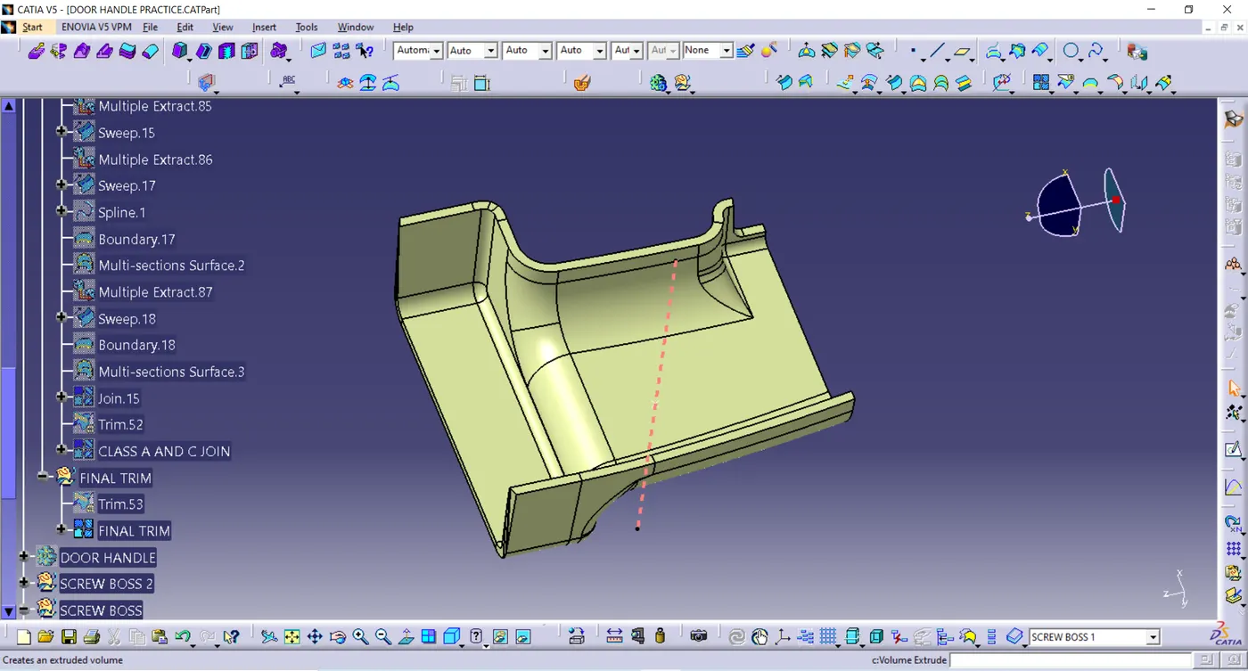
Creation of Engineering features
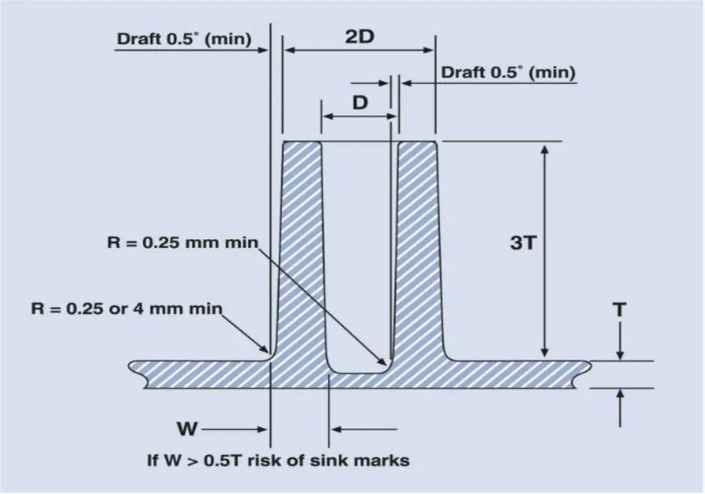
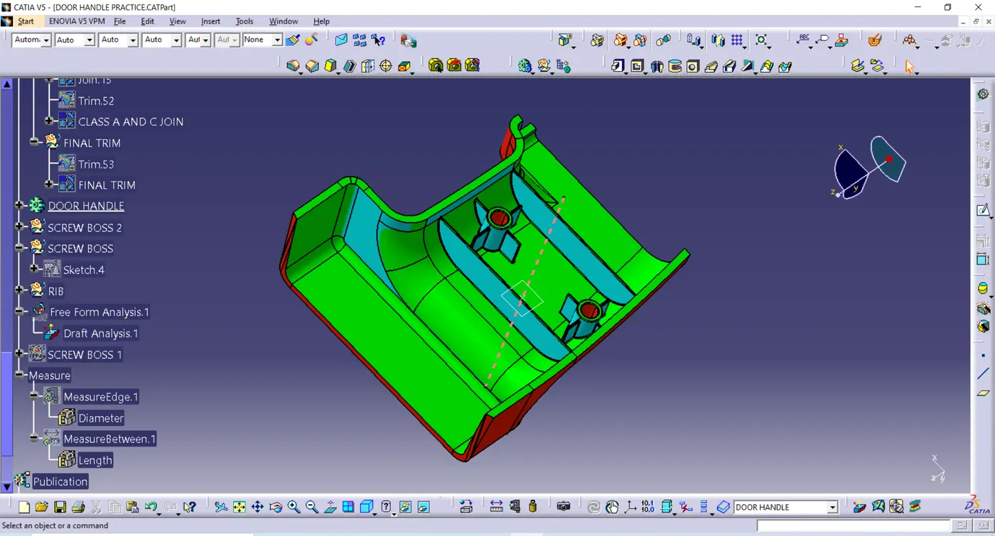
RIB:- Rib provides an economical way to increase stiffness and strength to the mould parts without increasing the overall thickness of the wall. It is thin protrusion that extended perpendicular from the wall.
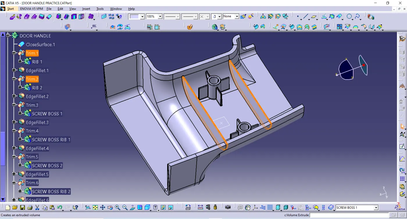
RIB ROOT THICKNESS :- To check the Rib root thickness, first take perpendicular intersection across the body and the Rib and then have to sketch a circle which tangent to the Rib base or root area by using tritangent type circle. The value must be within 30% greater of the wall thickness.
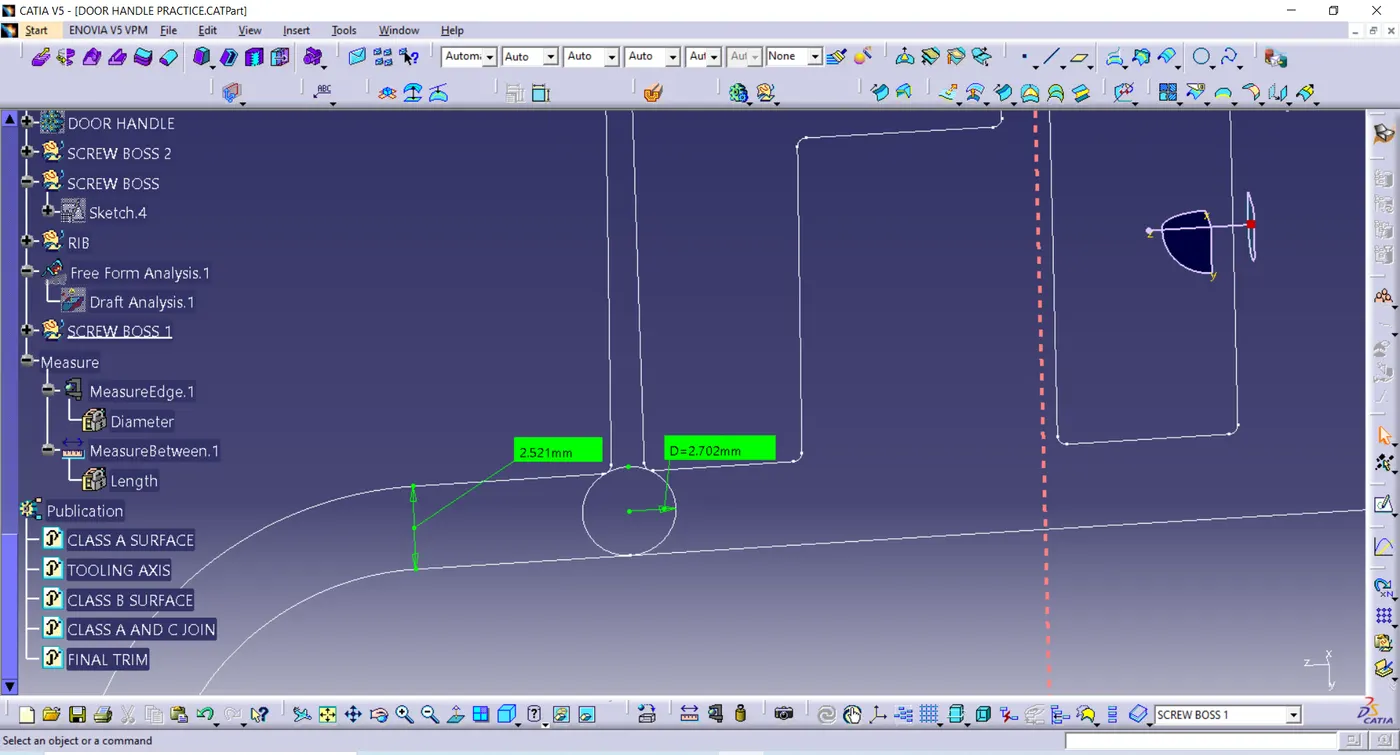
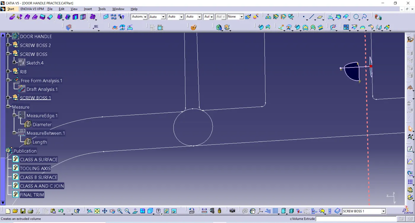
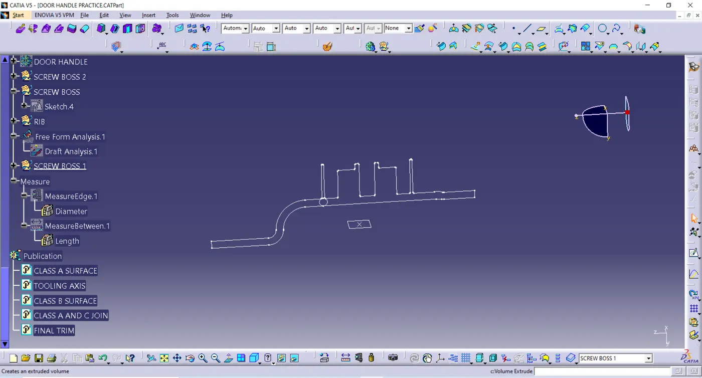
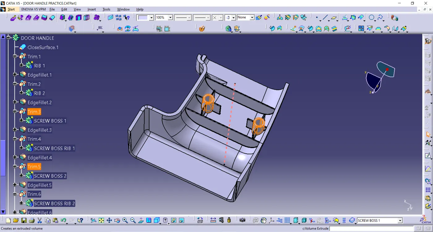
SCREW BOSS :- Screw boss are used as a point for attachment and assembly, most common in as cylindrical projection with hole design to receive screw or other types of fastening hardware.
DRAFT ANALYSIS:- First the class – A surface is checked before creating the Class –B&C surface and finally the solid body must be analysed. Both can be done by following the below procedures.By changing the view mode to custom view parameters – Material mode then the feature draft analysis is enabled.Then the compass was activated and placed with the tooling axis by dragging the red pointer and then locked it.Then, by selecting the quick analysis mode, the nominal value will be 3 degrees and checked for the component's draft angle.The green colour area shows that it satisfies the 3-degree draft angle. If not satisfied then by using the Running point tool the area is measured and then altered to get a successful draft for the created tooling direction.
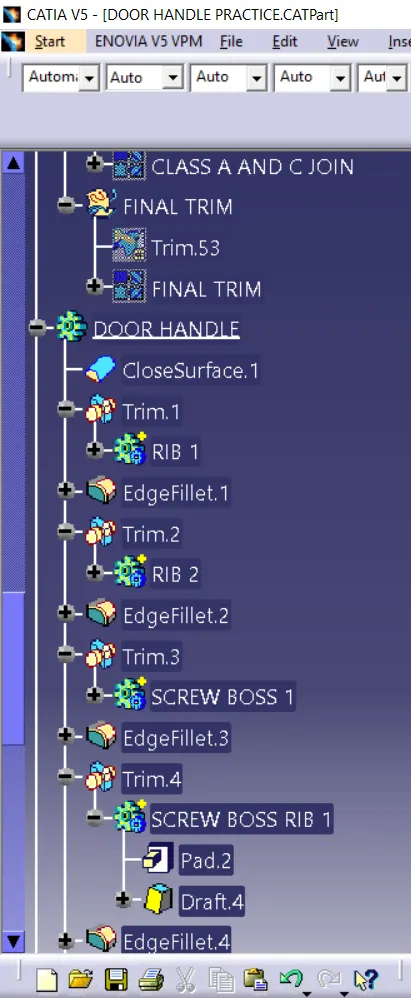
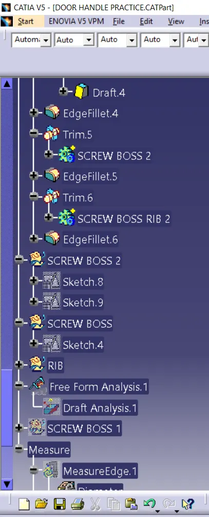
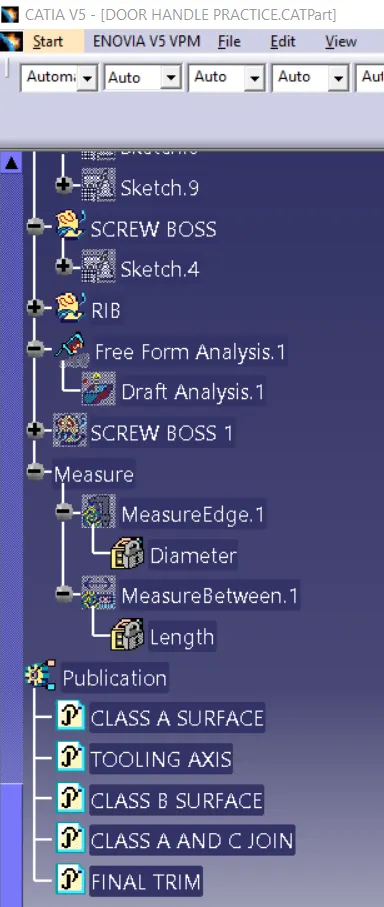
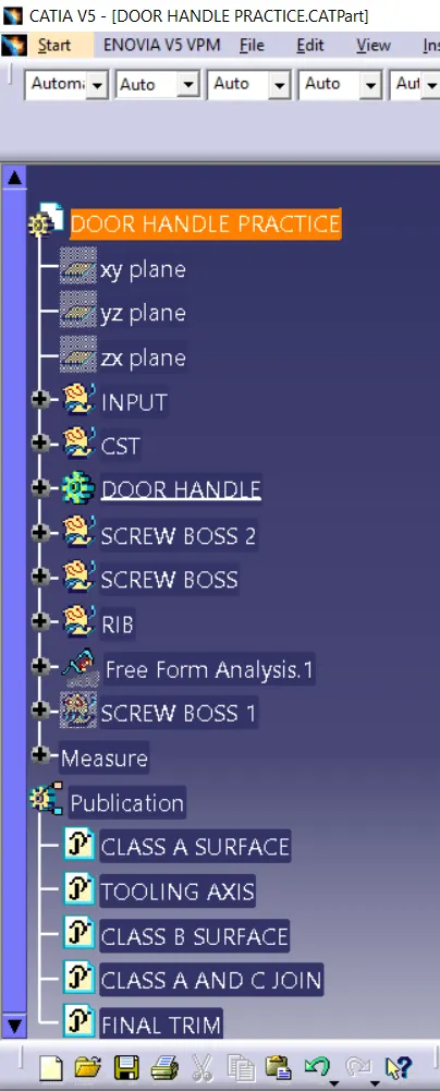
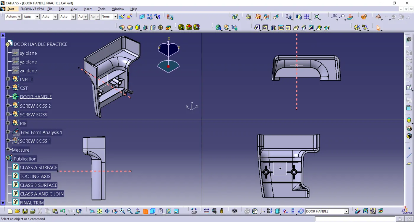
Tree structure:-
VIEWS OF SOLID :-
CONCLUSION:-
How to form the tooling axis when there are constraints .
To capture the class B and C properly.
To check the feasibility of the component.
How to form Rib and Screw .