Week 10 - Challenge 1- Attachment Feature Creation (Ribs & Screw Boss)
A REPORT ON (CHALLENGE) ATTACHMENT FEATURE CREATION (RIBS & SCREW BOSS)
AIM :-
- To create the door handle component from the given class-A Surface.
- To create the tooling axis for the given class-A surface meeting the requirements of the draft angle.
- To attach B side features in the component.
- To perform the draft analysis on the model.
CREATING TOOLING AXIS:
Normal To Surface method:
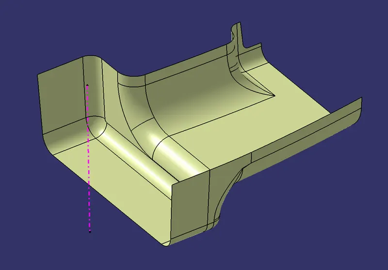
In this method extract one flat surface from the class A surface and create one point on the extracted surface. Create the dummy axis for tooling direction.
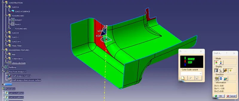
After creating of dummy axis, The Drafting analysis was performed using the Feature Draft Analysis command.
Using this command, the compass was set on the main tooling axis and the Draft angle was changed to 3 degrees. But, above 90% of the class A surface clear at 2.85degree. So, we have to inform the styling team to correct the class A.
DRAFT ANALYSIS:
The draft analysis technique is used to analyse whether our part model created in CAD is manufacturable based on the draft condition applied. Here the part should get easily removed from the panel dies or Mold (in case of plastic and sheet metal parts).
No parts can be ejected from the tool if it is having a straight 90-degree profile from its base surface. A small draft angle is provided to each and every area of the component in order to get easy removal of the component from the tool.
Here we are providing a direction in which components should eject in order to get easy removal of components from the tool. In other words, it also lets us know whether the model is having a draft angle and how much is the draft angle from the tool direction.
In this challenge tooling axis is created the following method:
CREATING CLASS B SURFACE:
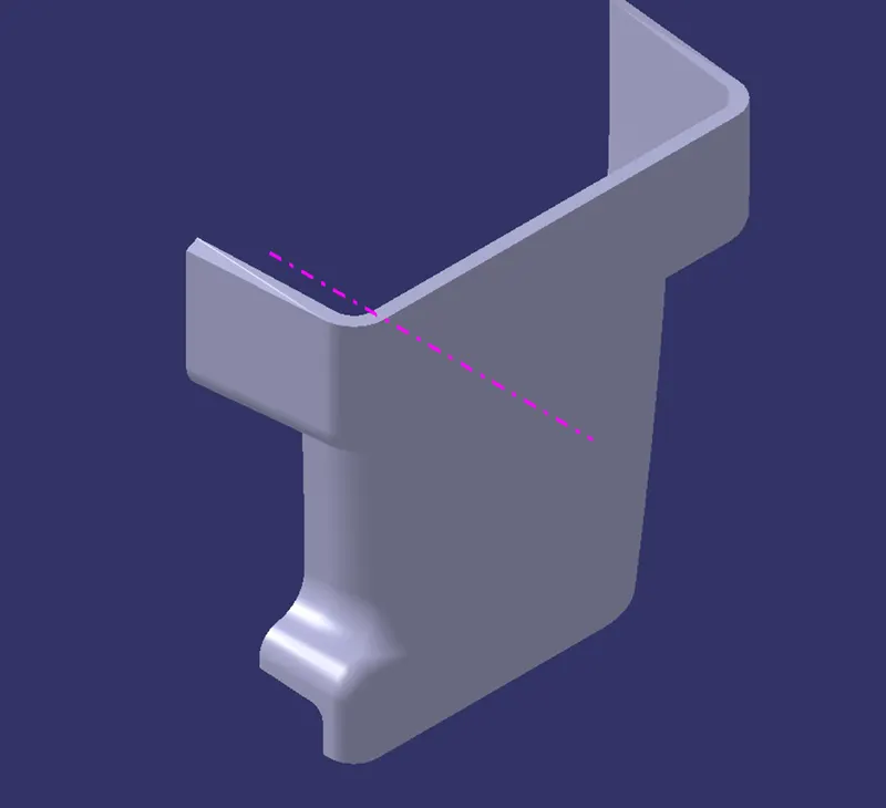
To create class B offset the class A surface of 2.5mm inside as per the given data. After offsetting the class, A, the class B surface create with some errors. So, to make good quality classB surface, the above surface further split and extrapolated surface where the fillet is forming and trim those extra surfaces and created the class B surface. The final class B surface as follows:
CREATING CLASS C SURFACE
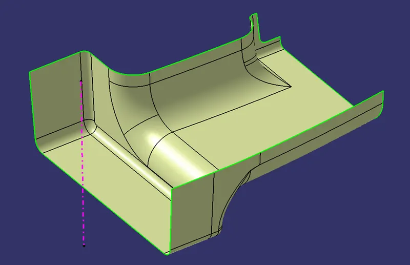
The Class C surface connects the Class A and Class B surface.
Initially the outline of the Class A surface was obtained using the Boundary
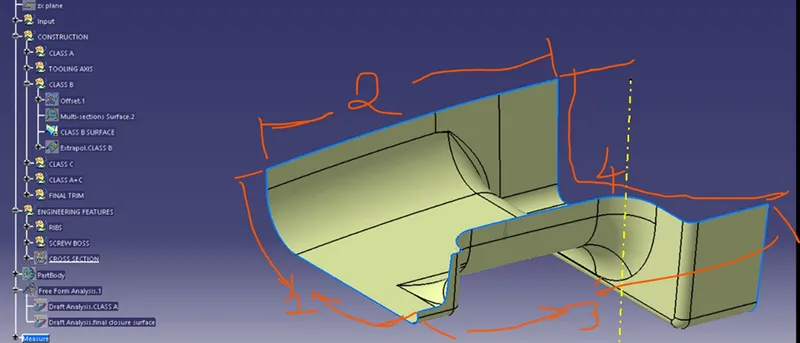
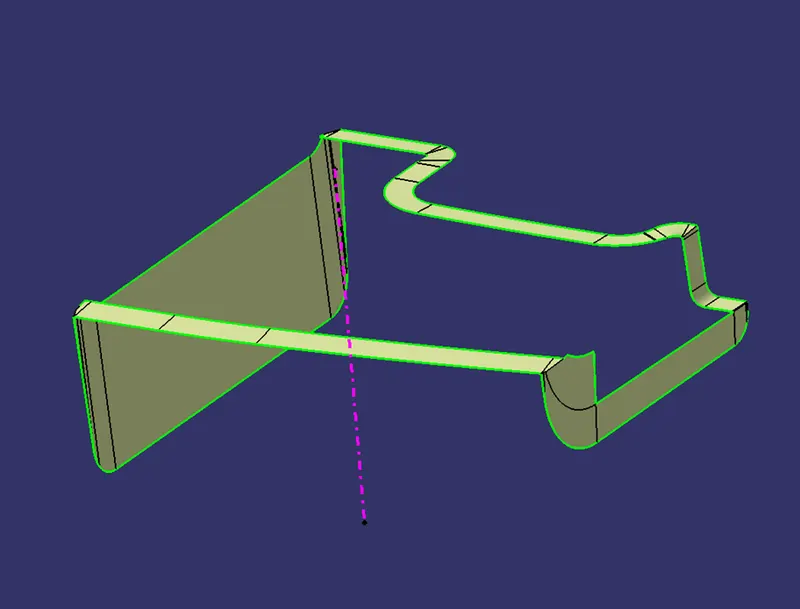
In this model there is two types of class C surfaces are there one is parallel to the draft axis and another is perpendicular to the draft (tooling) axis. The following edges are parallel to the tooling axis and the picture as follows:
The Sweep command was used along with draft direction, with a draft angle of 3 degree.
The final Class C surface looks as follows:
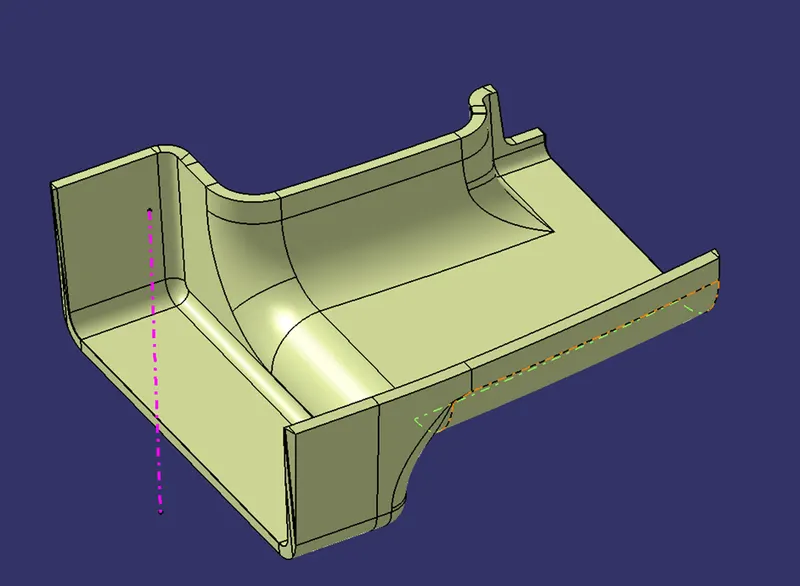
after creation of Class C we need to join A&C. Finally, all the 3 surfaces were trimmed to form a closed surface. (A, B, C Surfaces). The final trim to form close surface.
After forming the closer surface checking the surface with boundary option.
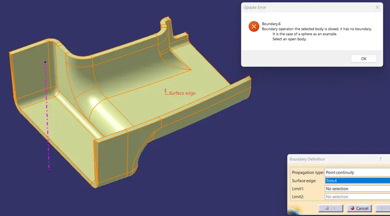
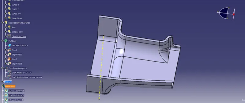
Because of closer surface the above error will appear. Now we shift to the part work bench to add the thickness to the model. The final thicken model as follows:
Now we go for draft analysis of solid body with 2.8 to 3 degrees.
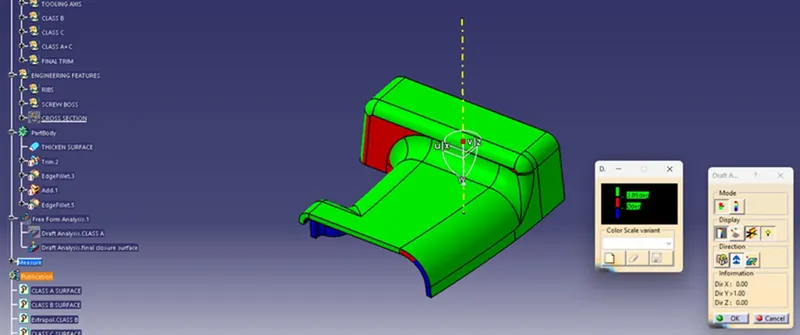
The above analysis of shows some of the surfaces are not clearing because of class A defects.
After the thickening class A surface the engineering feature are created to assemble the component with other components, reinforce the component without increasing the thickness of component.
RIB & SCREW BOSSES DESIGN
Engineering features are being as follows:
Ribs, Screw bosses, Locators, Heat stakes, Dog houses.
In this challenge we are creating the Ribs & Screw Bosses.
The design consideration for RIBS is: draft, Thickness, Height, Spacing, thickness at top, Rib root thickness.
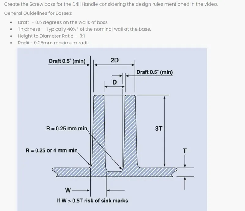
The design consideration for Screw is: draft, thickness, Height to diameter ratio, optional Radii, Boss gussets, coring out bottom, planning ahead type of ejection.
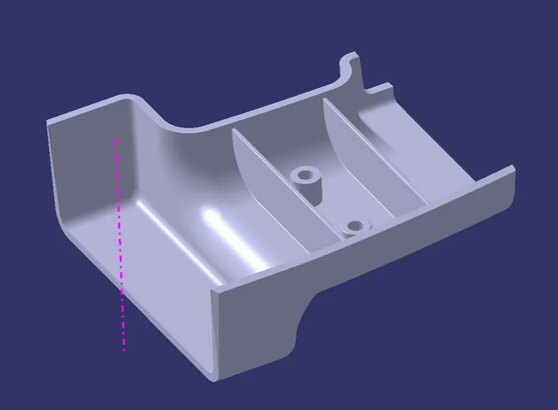
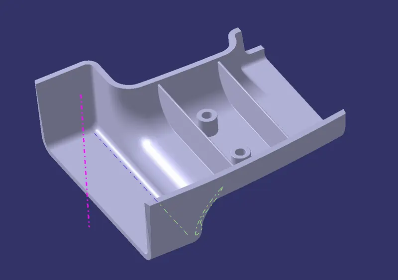
After creation of the above engineering features the component looks as follows:
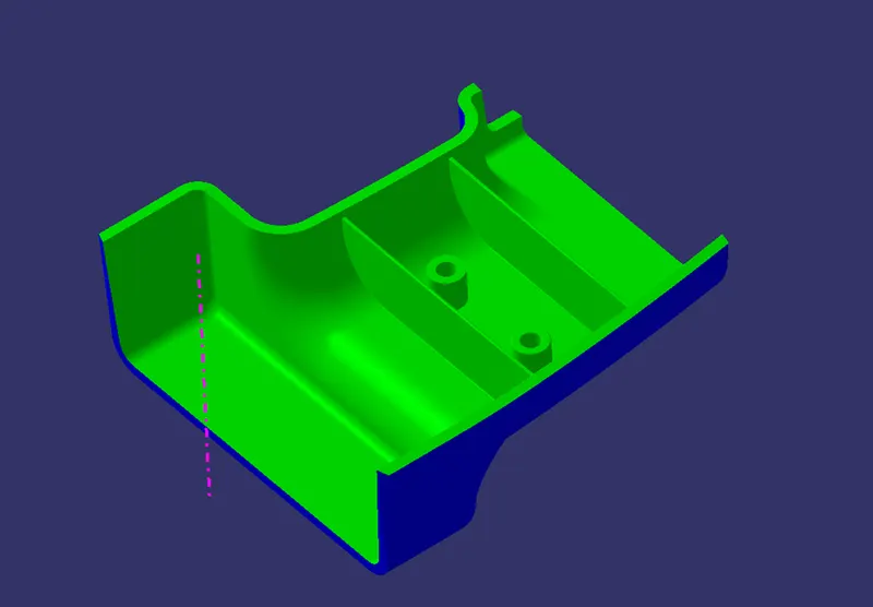
The draft analysis of final component as follows and clears at 0.48 degrees
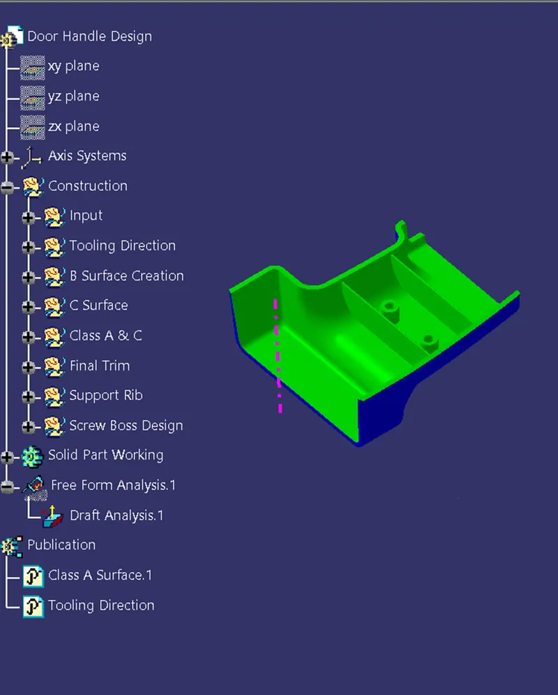
TREE STRUCTURE:-
The model tree created shows that all the geometrical sets are named for clarity.
ISOMETRIC VIEW
CONCLUSION:-
The Draft analysis of the component showed that the component is feasible to be moulded without any issues. Thus it satisfies all design and manufacturing criteria’s needed for a proper partThis concludes the report of Design of Rib and Screw Bosses .