Week 10 - Challenge 1- Attachment Feature Creation (Ribs & Screw Boss)
Aim:
The aim is to design the rib for the Drill Handle, ensuring compliance with the relevant design rules.
DOOR HANDLE
Tooling Axis creation:
The tooling axis is a crucial aspect of the design process as it determines the direction in which the mold/core and cavity will open. The selection of the tooling axis is based on the ease of ejecting components from the mold.
Upon analyzing the component, it was observed that the most easily ejectable direction is likely somewhere close to the Z direction (possibly inclined to it). To establish the tooling axis, a sketch was created on the YZ plane of the Axis System, forming a bisecting line that takes into account the two faces that might present difficulties during the tooling process. This bisecting line will aid in the efficient and smooth ejection of the part from the mold.
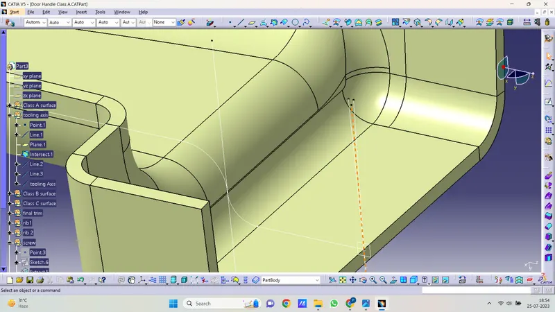
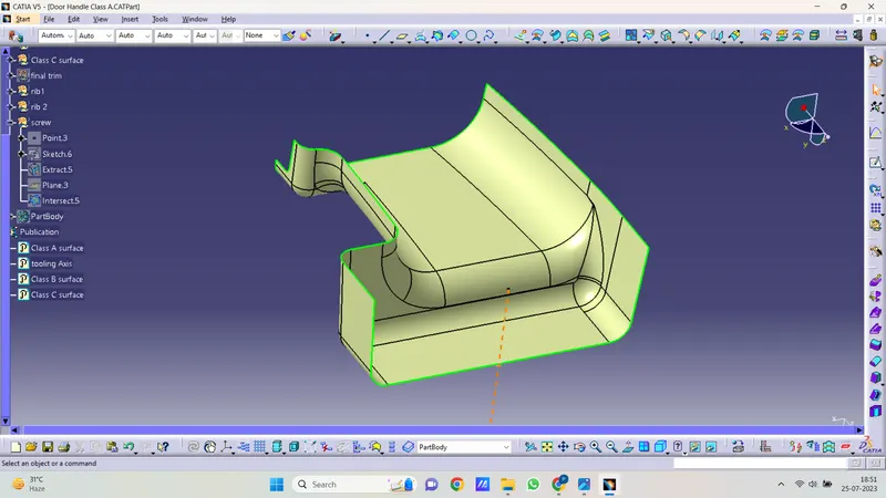
Class A surface:-
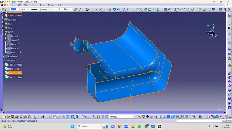
Class B surface:-
Class C surface:-
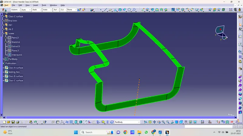
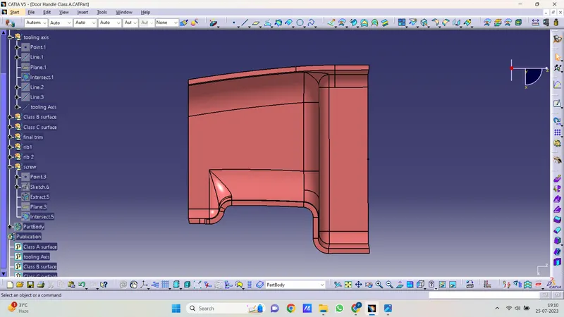
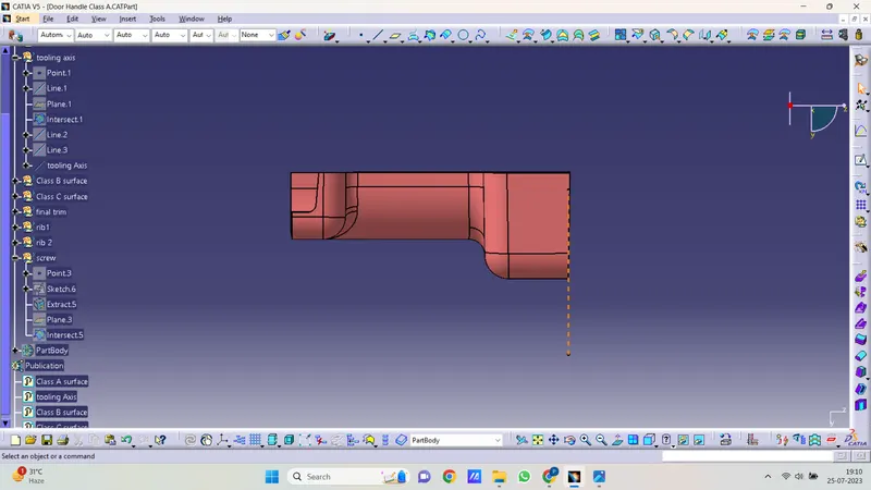
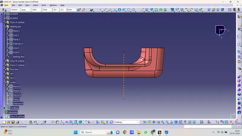
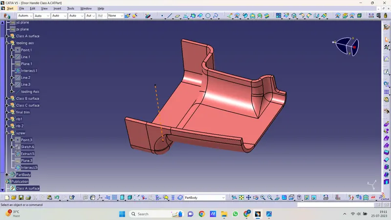
multiple views of part creation:-
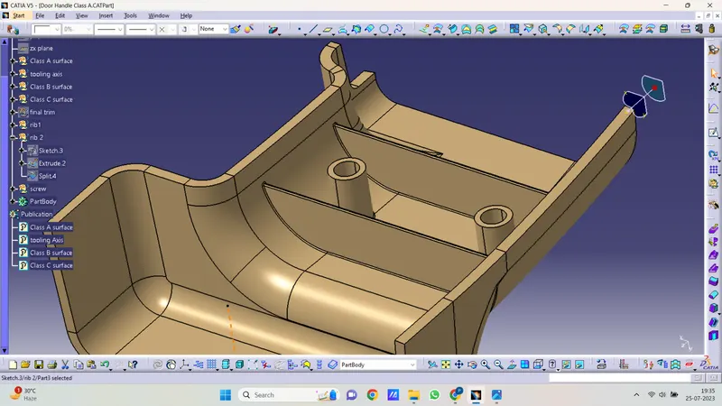
RIB CREATION
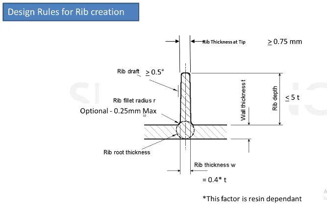
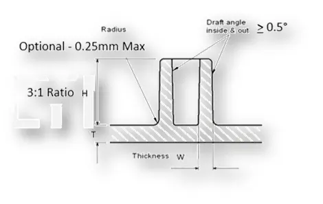
Design Principle for Rib Creation: Ribs are thin wall protrusions that extend perpendicularly from a wall or plane. They are commonly used to provide additional support and strength to a part. Ribs are typically found in clusters to offer support to a plane that would have otherwise been too thick, but they can also serve as stand-alone support for a single wall. The design of ribs must consider the thickness and location to ensure optimal structural integrity.
-
Base Surface Extraction: Begin by extracting the base surface where the rib needs to be created. Utilize the Extract command to obtain the required surface.
-
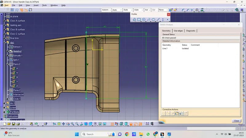
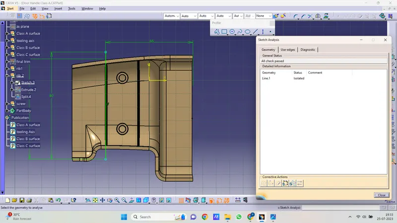
Sketching the Rib Profile: Create a positioned sketch and draw the profile for the rib. Ensure the dimensions and proportions align with the intended design and functional requirements.
-
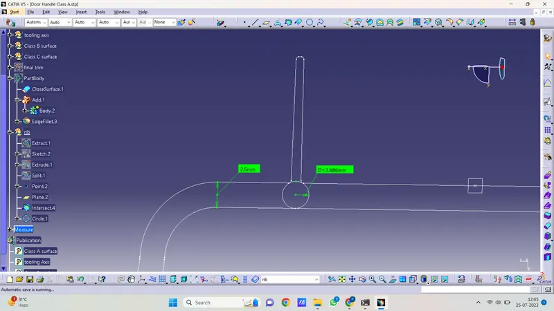
Extrusion for Height Calculation: To determine the height of the rib (h), extrude the profile. The height (h) can be calculated as follows: h = Wall thickness * 5 In the given example: h = 2.5 mm * 5 h = 12.5 mm
-
Thicken the Extruded Surface: Thicken the extruded surface to achieve the desired rib thickness (w). The thickness (w) can be calculated using the formula: w = 0.4 * t In the given example: w = 0.4 * 2.5 mm w = 1 mm
Therefore, the final rib design will have a height (h) of 12.5 mm and a thickness (w) of 1 mm, providing the necessary support and strength to the part.
constrain sketches:-
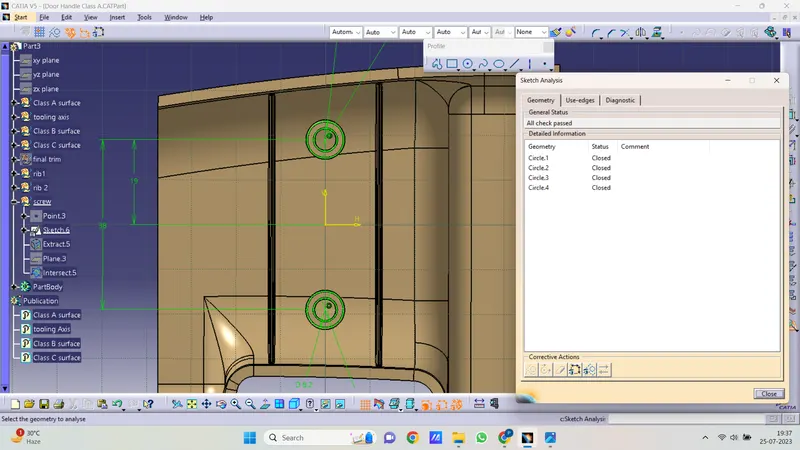
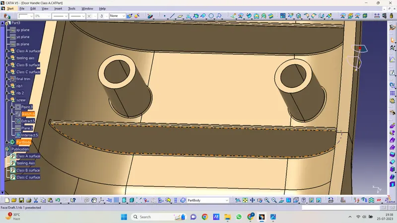
Screw boss design:-
Draft analysis:-
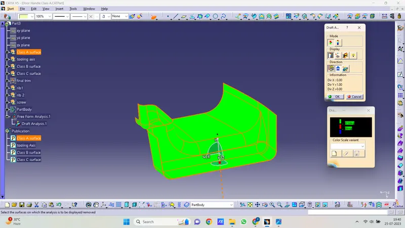
Draft analysis of class A surface:-
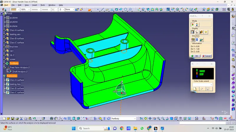
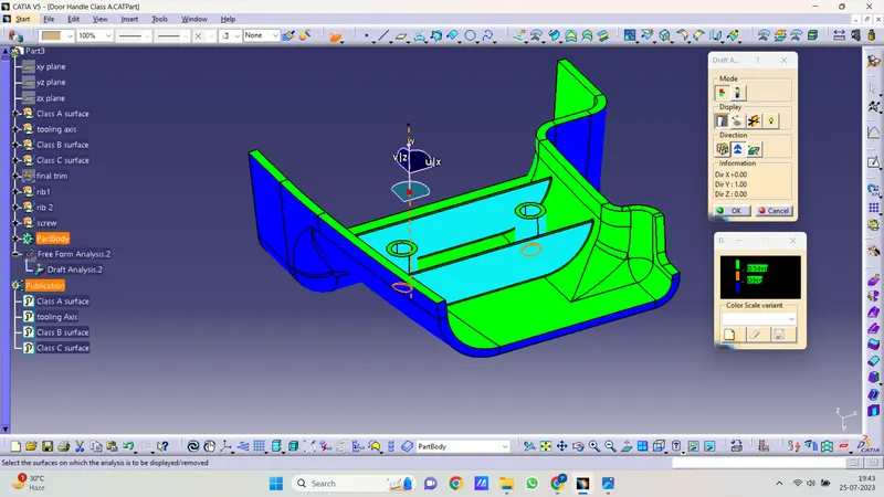
Draft analysis of part body:-
conclusion:-
the tooling axis for the SolidCAT part has been successfully established based on the analysis of the given Class A Surface. The selection of the tooling axis was done to ensure ease of component ejection during the manufacturing process. Additionally, B Side Features have been incorporated into the design to