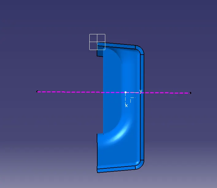
Week 10 - Challenge 1- Attachment Feature Creation (Ribs & Screw Boss)
AIM-:
- CREATE THE CLASS B AND CLASS C SURFACE.
- CREATE SOLID BODY OF DOOR HANDLE.
- CREATE RIBS AND SCREW BOSS ON DOOR HANDLE WITH PROPER DIMENSION.
- DRAFT ANNALYSIS OF CLASS A AND FINAL SURFACE.
A. TREE STRUCTURE
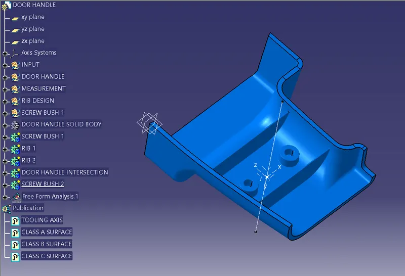
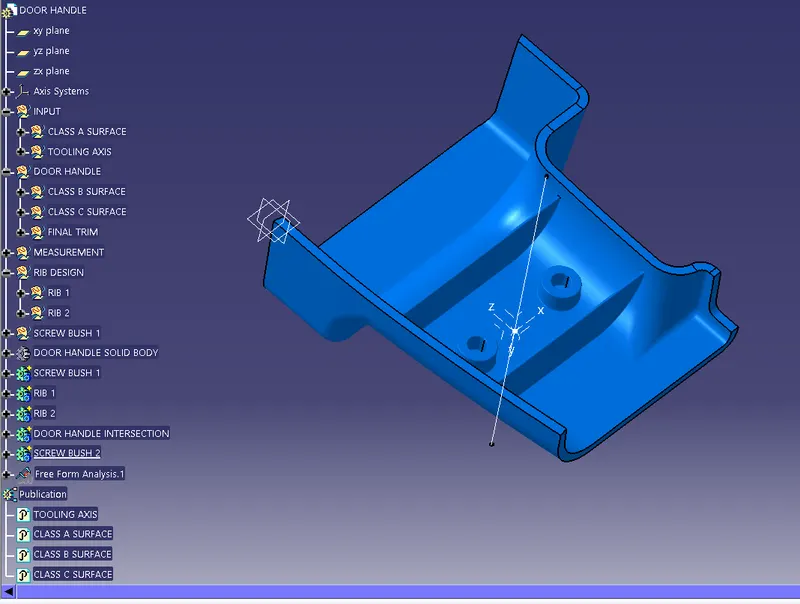
B. DETAIL TREE STRUCTURE
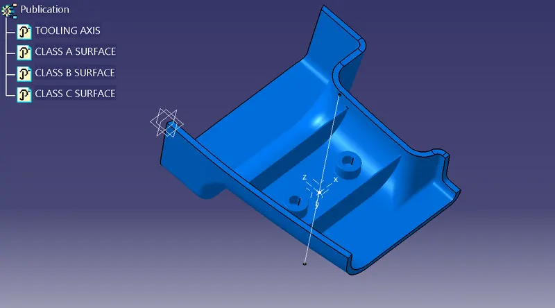
C. PUBLICATION
D. PROCEDURE OF DUMMY TOOLING AXIS
1. EXTRACT THE BASE
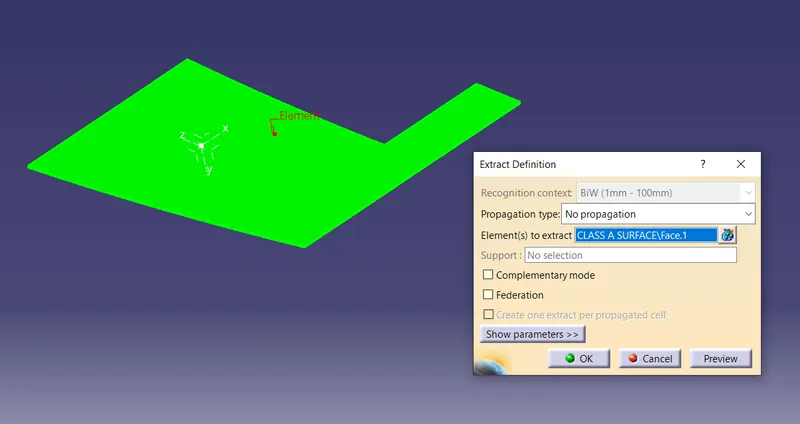
- Choose the "Extract" command in "Operation" toolbar.
- Select the base of "CLASS A SURFACE".
- Choose "No propagation" option in "Propagation type" then click ok.
- Base is automatically extracted.
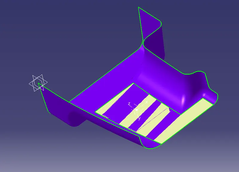
2. CREATE POINT
- Choose "Point" command in "Wireframe" toolbar.
- Choose "On surface" in "Point type".
- Select extracted surface in "Surface".
- Choose "Coarse" in "Dynamic positioning" option.
- Enter 11.57mm distance value.
- Point is created automatically on surface.
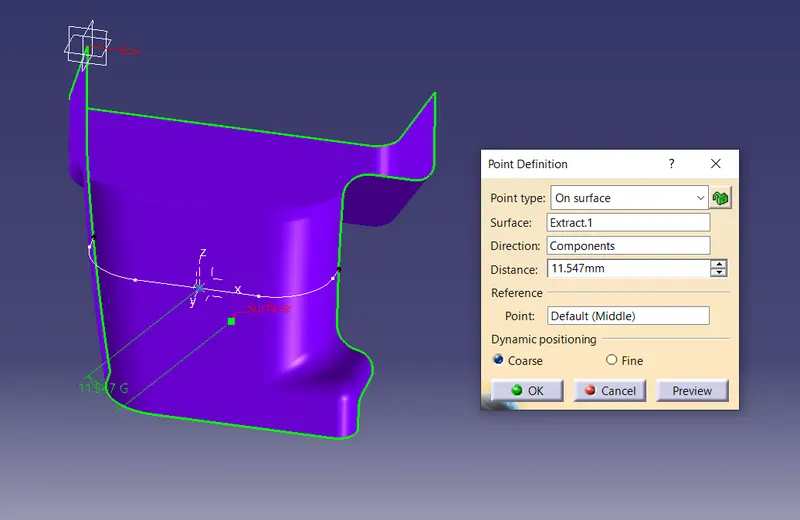
3. CREATE AXIS ON POINT
- Go to the "Insert" then "Axis system" then "Axis system"
- Choose "Standard" option "Axis system type".
- Select the point in "Origin".
- Deselect the "Current" option, then click ok.
- Axis is created in the point.
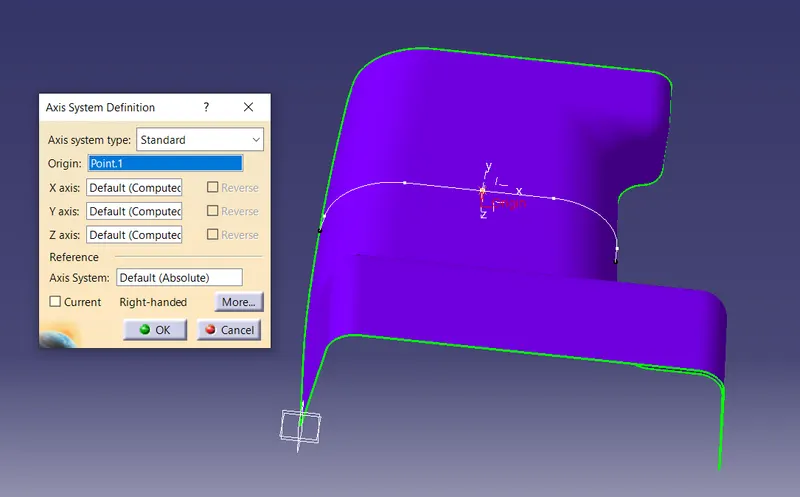
4. CREATE DUMMY TOOLING AXIS-1
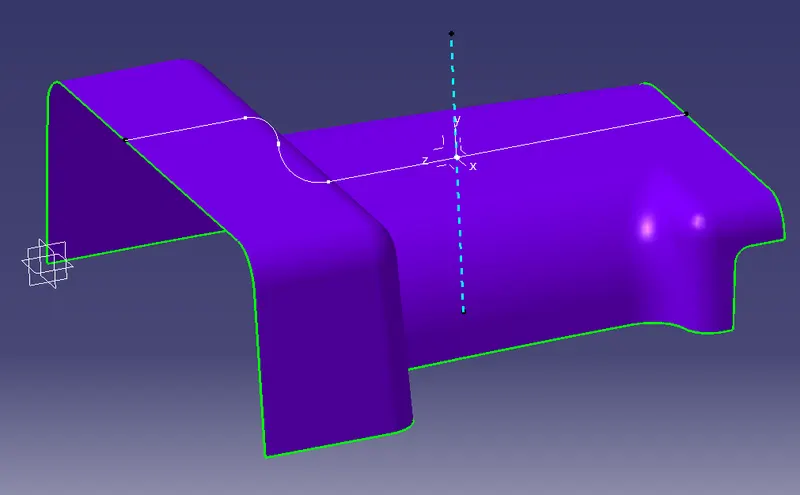
a) CREATE INTERSECTION LINE
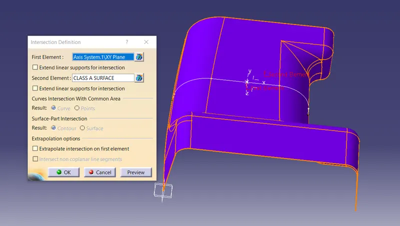
- Choose "Intersection" command in "Wireframe" Toolbar.
- Select the "Axis System/XY axisPlane" in "First Element".
- Select the "CLASS A SURFACE" in "Second Element", then click ok.
- Intersection line is created automatically.
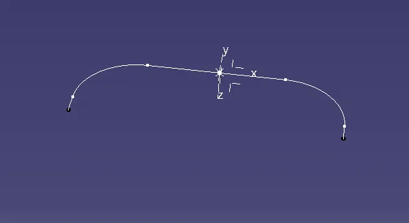
b) CREATE THE LINE ON TAPER SECTION OF INTERSECTION LINE
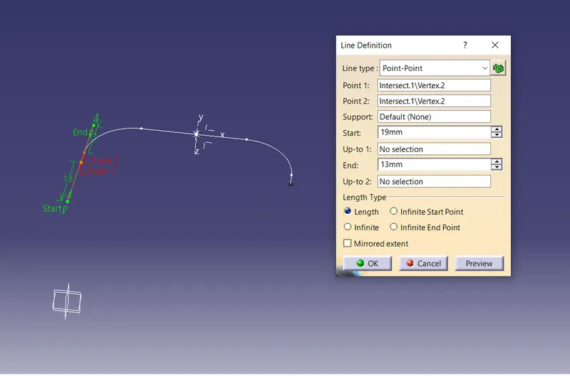
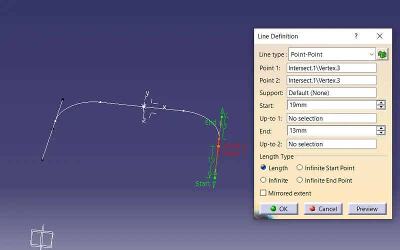
- Choose "line" command command in "Wireframe" Toolbar.
- Select the "Point-Point" option in "Line type".
- Select the Point 1 and Point 2 in Intersection line.
- Enter the value of Start and End limit.
- Line is created automatically.
- Same line is created in opposite side in taper section.
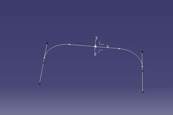
c) BISECTING LINE TO CREATE DUMMY TOOLING AXIS 1
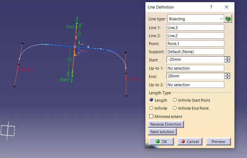
- Choose "line" command command in "Wireframe" Toolbar.
- Select the "Bisecting" option in "Line type".
- Seclect Line 1 and line 2 which is created earlier.
- Select the point.
- Enter the value of Start and End limit.
- The main tooling axis is created.
5. CREATE DUMMY TOOLING AXIS-2
a) CREATE INTERSECTION LINE
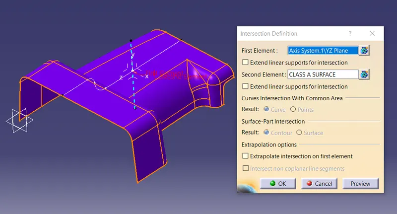
- Choose "Intersection" command in "Wireframe" Toolbar.
- Select the "Axis System/YZ axisPlane" in "First Element".
- Select the "CLASS A SURFACE" in "Second Element", then click ok.
- Intersection line is created automatically.
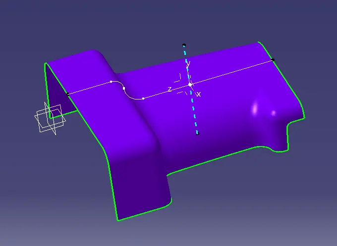
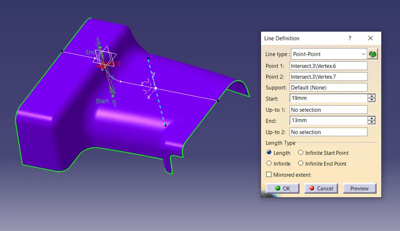
b) CREATE THE LINE ON TAPER SECTION OF INTERSECTION LINE
- Choose "line" command command in "Wireframe" Toolbar.
- Select the "Point-Point" option in "Line type".
- Select the Point 1 and Point 2 in Intersection line.
- Enter the value of Start and End limit.
- Line is created automatically.
- Same line is created in opposite side in taper section.
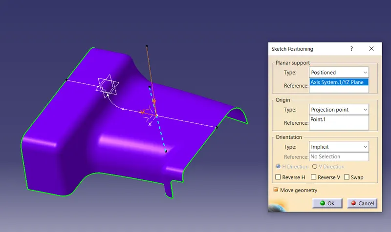
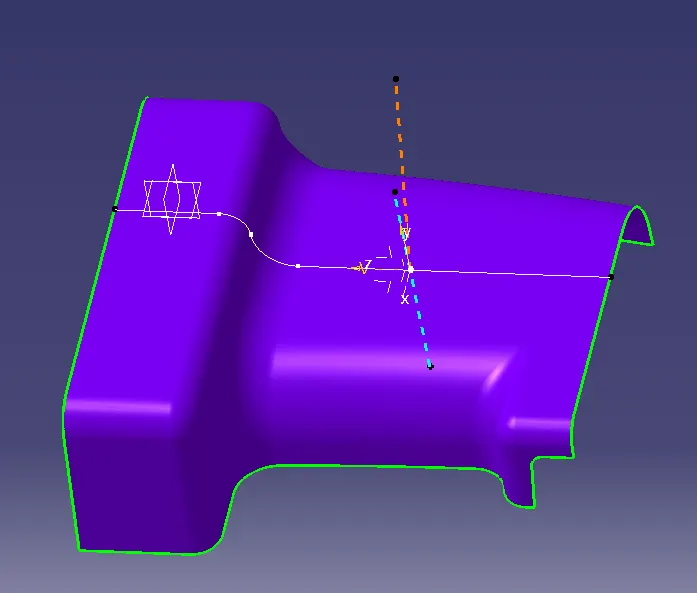
c) CREATE POSITION SKETCH
- Go to the "Positioned Sketch" command.
- Select the Axis system "YZ Plane" in "Reference".
- Choose "Projection point" in "Type" option.
- Select the point in "Reference".
- Set the horizontal "H Direction" and vertical "V Direction" as per required.
- Then click ok, Sketch page is opened
d) CREATE DUMMY TOOLING AXIS-2
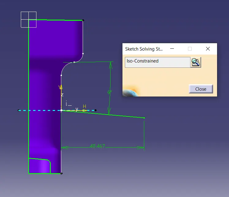
- Create line by choosing point and "6 degree" from taper line to this line.
- Apply taper line as "Construction/Sstandard Element"
- Give dimension for "Iso-Constrained" sketch solution.
- Then exit from sketch work bench.
- Right click on sketch (Tree structure), go to the "Properties", give name as Dummy Tooling axis 2.
E. PROCEDURE OF BISECTING METHOD
6. CREATE THE MAIN TOOLING AXIS
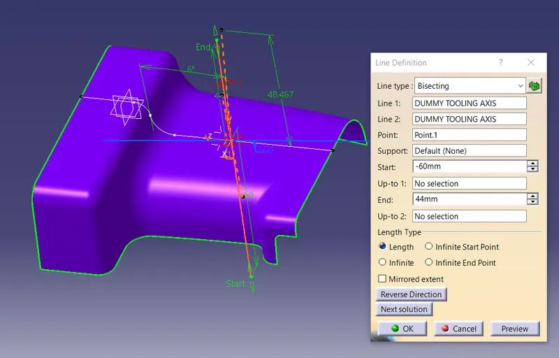
- Choose "line" command command in "Wireframe" Toolbar.
- Select the "Bisecting" option in "Line type".
- Seclect Dummy Tooling axis 1 and Dummy Tooling axis 2 which is created earlier.
- Select the mid point of circle.
- Enter the value of Start and End limit.
- The main tooling axis is created.
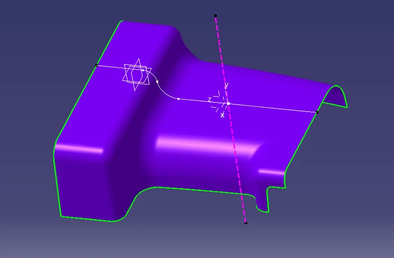
F. PROCEDURE OF DRAFT ANALYSIS OF CLASS A SURFACE
- Go to "Insert" toolbar, then choose "Analysis", then choose "Feature Draft Analysis".
- Choose "CLASS A SURFACE" in "Element" option.
- Choose "Shows or hide the color scale" in "Display" option.
- Deselct the "Analyses under the running point" if you don't want to check the running point angle.
- Select "Uses the compass to define the new current draft direction" option.
- Drag the compass and placed it in Tooling axis line vertically.
- Choose "Inverses the draft direction" option as per required.
- Choose "Switch on the quick analysis mode".
- Enter the draft angle value by double clicking on it.
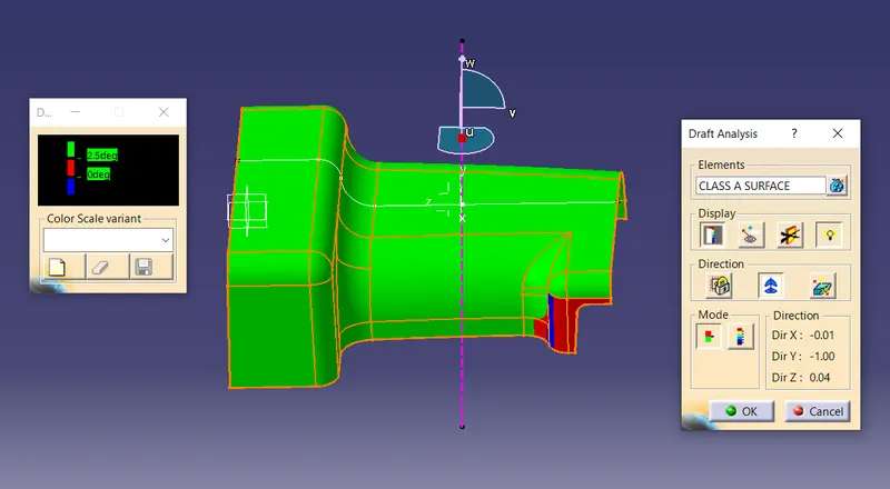
RESULT-:
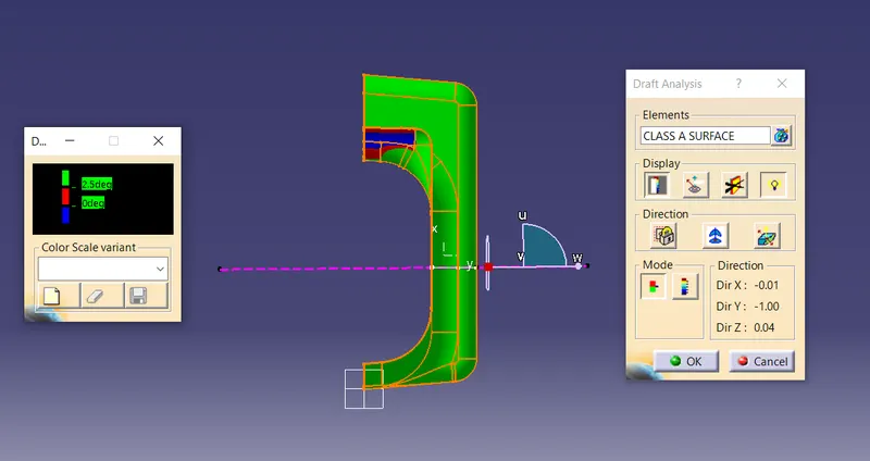
- If "CLASS A SURFACE" show green colour in top side, it means it created with proper draft angle in limit and no further correction required for this surface.
- If "CLASS A SURFACE" show Red or Blue colour in top side, it meand the draft angle is not given in limit and then correction or working is required on this surface.
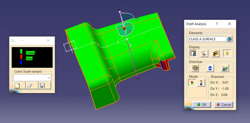
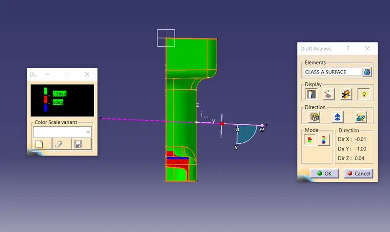
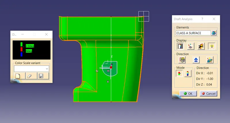
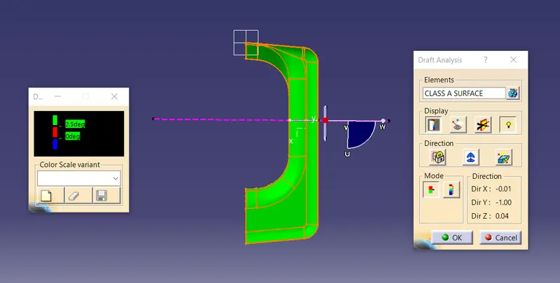
G. SCREENSHOT OF DRAFT ANALYSIS (ALL VIEW)
1. ISOMETRIC VIEW
2. FRONT VIEW
3. SIDE VIEW
4. TOP VIEW
5. BOTTOM VIEW
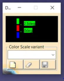
6. COLOUR SCALE
H. DRAFT ANALYSIS OF SOLID BODY
- Go to "Insert" toolbar, then choose "Analysis", then choose "Feature Draft Analysis".
- Choose "CLOSE SURFACE" in "Element" option.
- Choose "Shows or hide the color scale" in "Display" option.
- Deselct the "Analyses under the running point" if you don't want to check the running point angle.
- Select "Uses the compass to define the new current draft direction" option.
- Drag the compass and placed it in Tooling axis line vertically.
- Choose "Inverses the draft direction" option as per required.
- Choose "Switch on the quick analysis mode".
- Enter the draft angle value by double clicking on it.
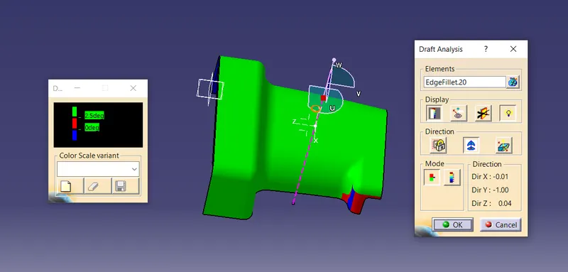
RESULT-:
- If "CLASS A SURFACE" show green colour in top side, it means it created with proper draft angle in limit and no further correction required for this surface.
- If "CLASS A SURFACE" show Red or Blue colour in top side, it meand the draft angle is not given in limit and then correction or working is required on this surface.
I. SCREENSHOT OF DRAFT ANALYSIS OF FINAL COMPONENT (UPPER SIDE)
1. ISOMETRIC VIEW
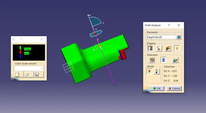
2. FRONT VIEW
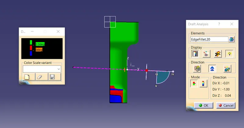
3. SIDE VIEW
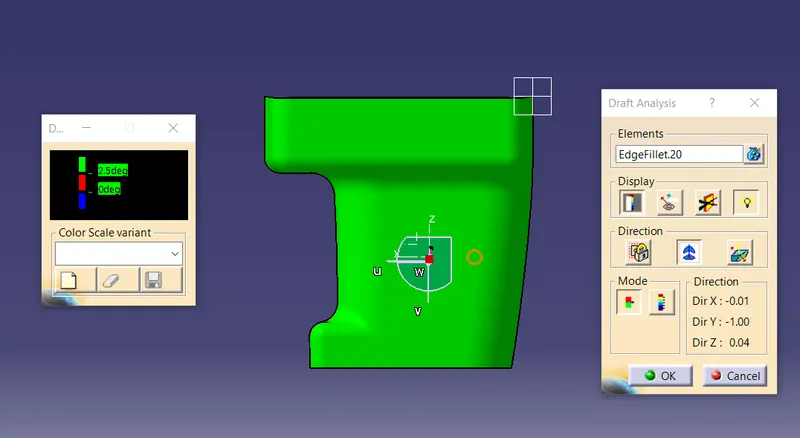
4. TOP VIEW
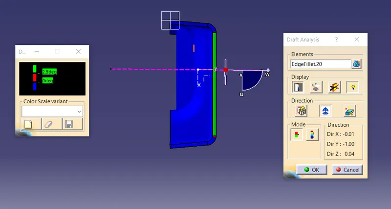
5. BOTTOM VIEW
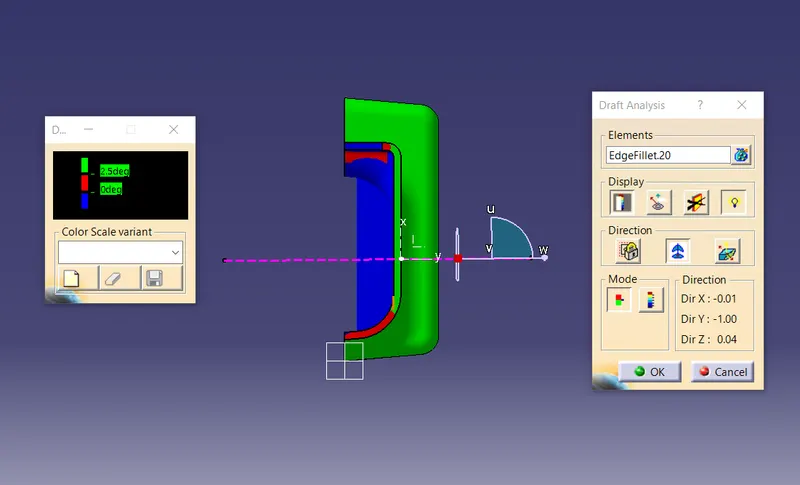
6. COLOUR SCALE
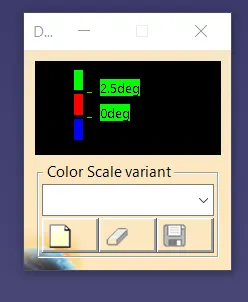
J. DRAFT ANNALYSIS ON FINAL COMPONENT
- Go to "Insert" toolbar, then choose "Analysis", then choose "Feature Draft Analysis".
- Choose "CLOSE SURFACE" in "Element" option.
- Choose "Shows or hide the color scale" in "Display" option.
- Deselct the "Analyses under the running point" if you don't want to check the running point angle.
- Select "Uses the compass to define the new current draft direction" option.
- Drag the compass and placed it in Tooling axis line vertically.
- Choose "Inverses the draft direction" option as per required.
- Choose "Switch on the quick analysis mode".
- Enter the draft angle value by double clicking on it.
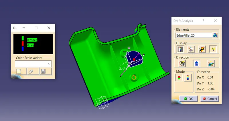
RESULT-:
- If "CLASS A SURFACE" show green colour in top side, it means it created with proper draft angle in limit and no further correction required for this surface.
- If "CLASS A SURFACE" show Red or Blue colour in top side, it meand the draft angle is not given in limit and then correction or working is required on this surface.
K. DRAFT ANALYSIS SCREENSHOT OF FINAL COMPONENT (BOTTOM SIDE)
1. ISOMETRIC VIEW
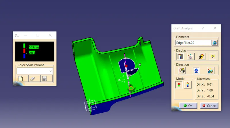
2. FRONT VIEW
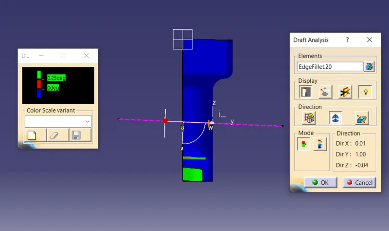
3. SIDE VIEW
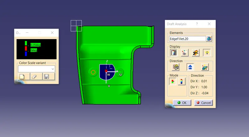
4. TOP VIEW
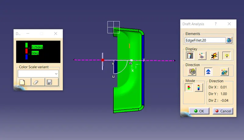
5. BOTTOM VIEW
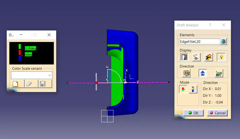
6. COLOUR SCALE
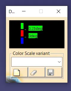
L. RIB DESIGN
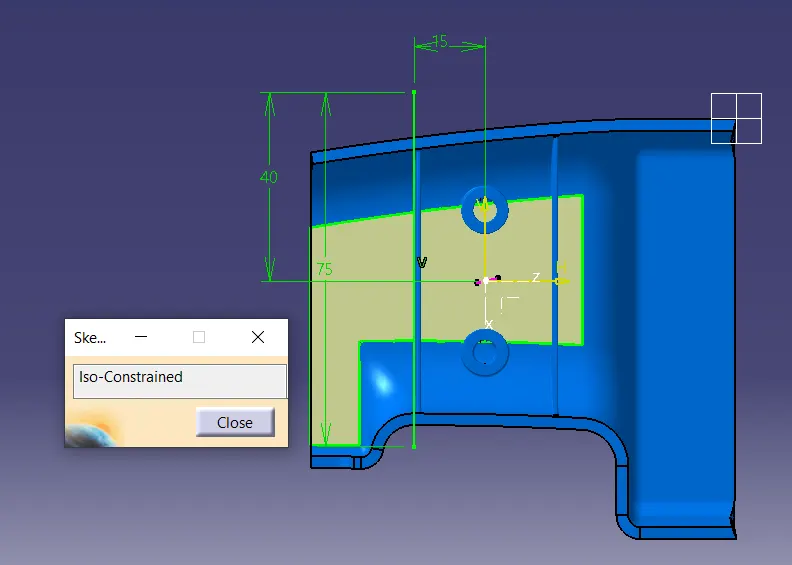
1. SKETCH
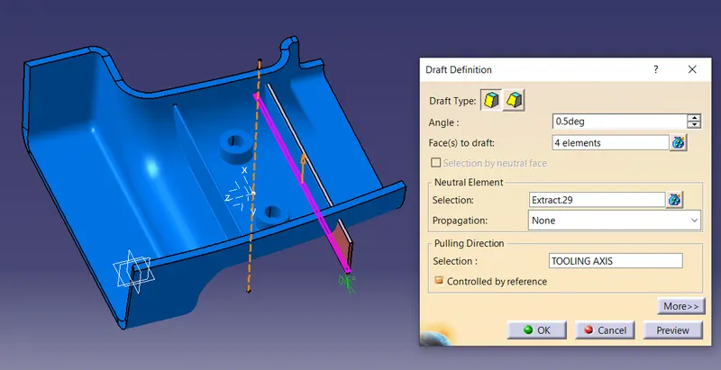
2. DRAFT ANGLE
Minimum Draft angle per side = 0.5degree
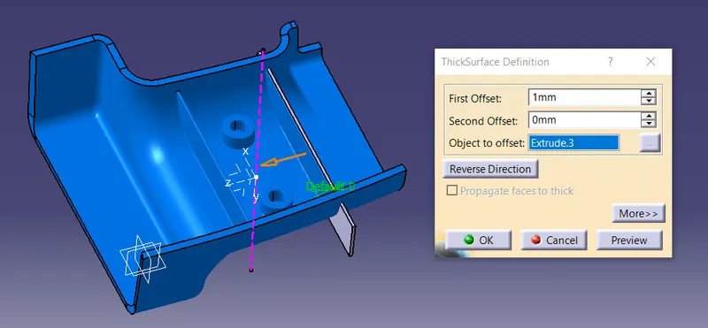
3. RIB THICKNESS
W=0.4*t
=0.4*2.5
=1mm
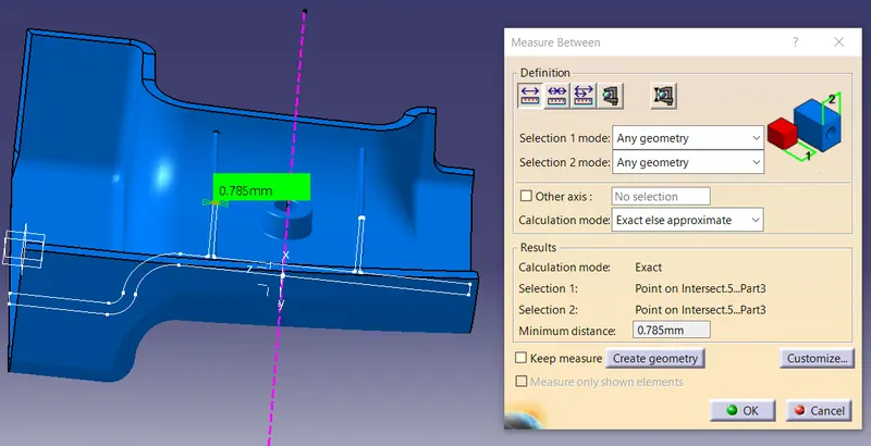
4. MINIMUM RIB THICKNESS
Thickness at RIB Tip = 0.75mm
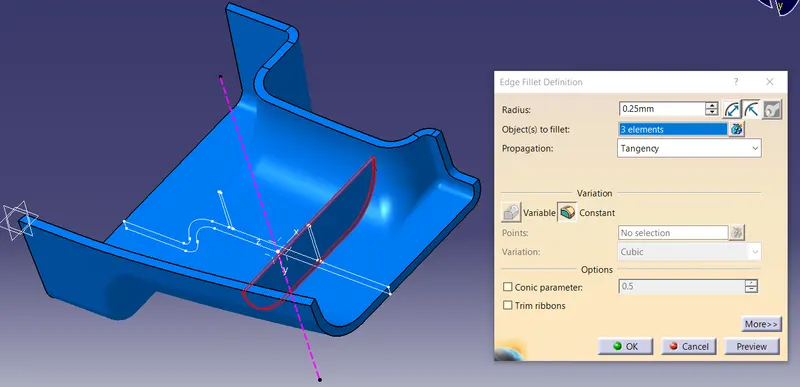
5. RIB FILLET RADIUS
Optional Rib Fillet radius = 0.25mm Maximum
Must not violet 40%* thickness requirement.
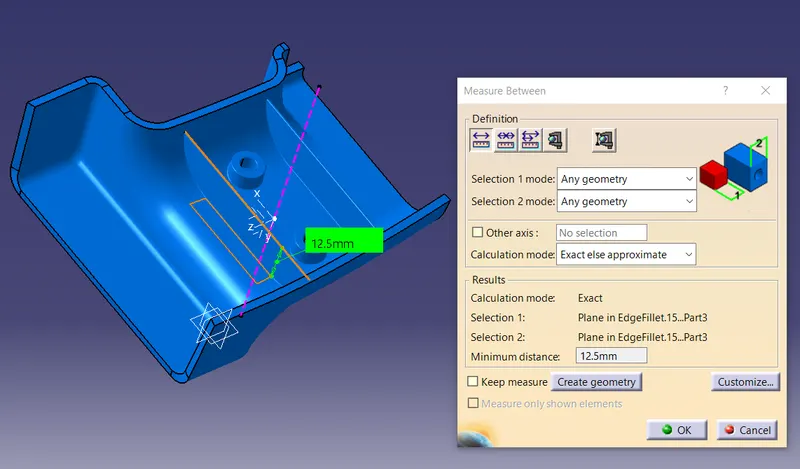
6. RIB HEIGHT/DEPTH
Rib height < 5*nominal wall thickness.
= 5*2.5 = 12.5mm
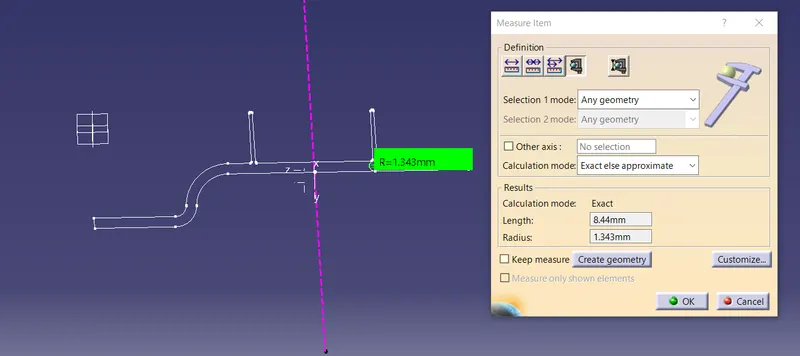
7. RIB ROOT THICKNESS
M. SCREW BOSS DESIGN
1. SKETCH
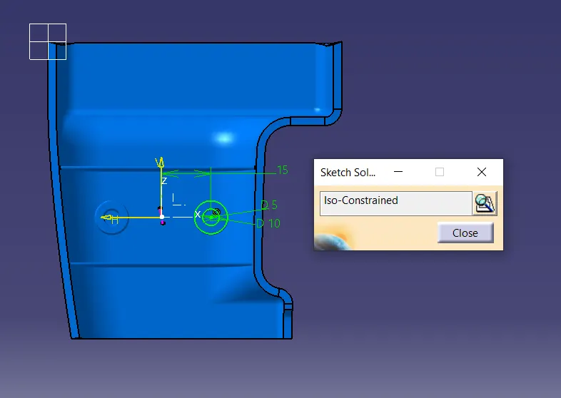
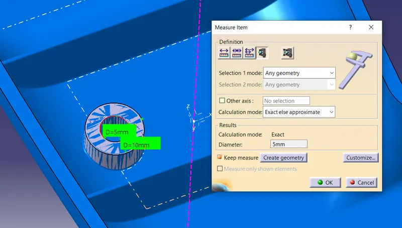
2. DIAMETER
DIA -1 (D)=5mm
DIA-2 )2D) = 10mm
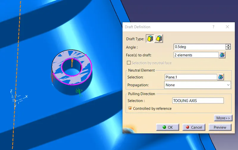
3. DRAFT
Draft angle = 0.5degree minimum
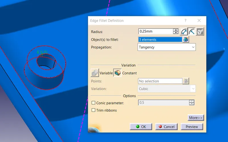
4. EDGE FILLET
Edge fillet radius = 0.25mm minimum
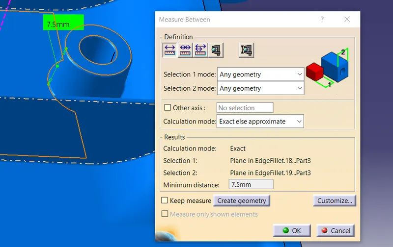
5. HEIGHT
Height= 3T
= 3*2.5
= 7.5mm
6. THICKNESS OF BOSS
W= Greater than 0.5T
= 0.5*2.5
= 1.25mm
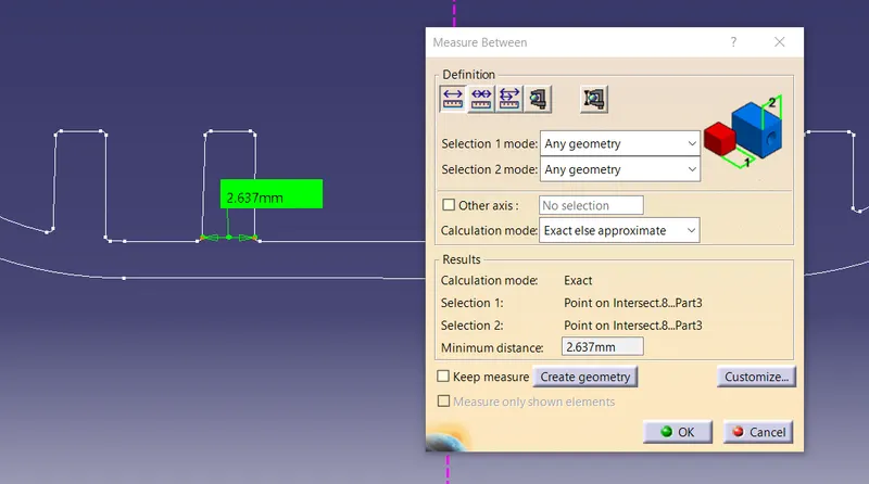
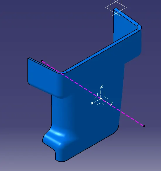
N. SCREENSHOT OF FINAL COMPONENT
1. ISOMETRIC VIEW
2. FRONT VIEW
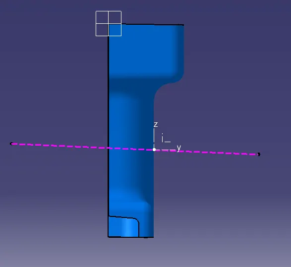
3. SIDE VIEW
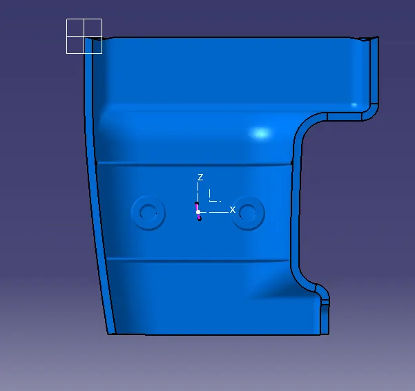
4. TOP VIEW