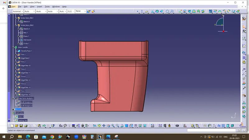
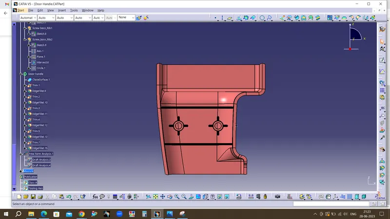
Week 10 - Challenge 1- Attachment Feature Creation (Ribs & Screw Boss)
OBJECTIVE
- To design Door handle as per automotive industry Standard.
- Create tooling axis for the given CLASS-A surface.
- Create B Class and C Class surfaces.
- Create final surface model and convert it into solid body using close surface command in the part design workbench.
- Create Ribs and Screw boss for drill handle.
- Perform draft analysis for both Class-A surface and Final part body.
DESIGN METHODOLOGY
- Skin data would be provided to us by the styling team.
- Class-A surface means visible surface. It gives the aesthetic of the component which is created by the styling team and gives to the part design engineer to create the part with all engineering aspects.
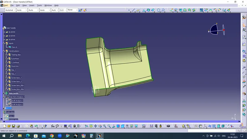
- The first step is to check the continuity of the class A surface. This is to ensure that there is no gap between surfaces. If we find any then we should fix that first.
- Class-A continuity check.
- Analyse the class A surface through visual inspection.
- To make sure that the given surface has no gap in between them. We can check it also with the help of Join or boundary commands.

Procedure for creating the tooling axis
Tooling axis represents the opening and closing of the mold core and cavity during the manufacturing of the components. A plastic product designer should consider the best tooling direction to cutdown the cost of the component very less.
Method opted for creating tooling axis for the door handle
- Check the best tooling direction for the given surface.
- We can find out the best tooling direction by cross checking all the three axes.
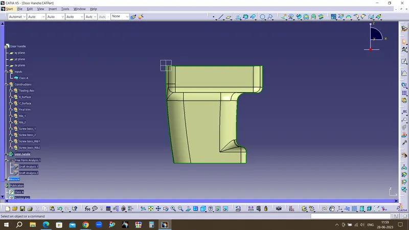
- Here we can find out that the best tooling direction for the pumper class-A surface is along Y-axis direction
Creating tooling axis
We should create a Dummy tooling axis first by creating point and line.
Select the curve in existing class A surface and create a dummy tooling axis for reference.Highlighted green colour is tooling axis.
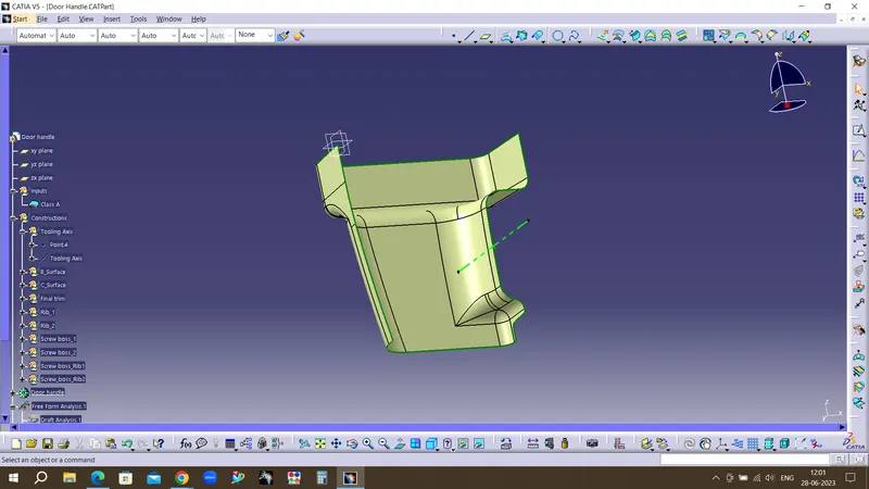
Draft analysis for the given CLASS-A surface
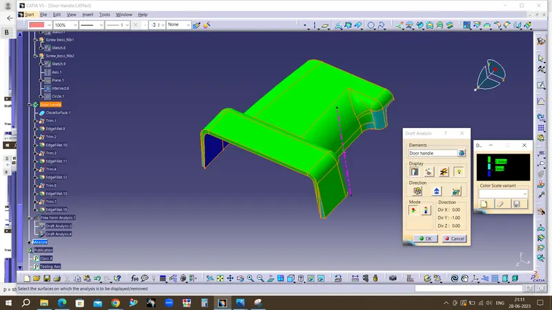
The Draft Analysis is a command enables you to detect if the part you drafted will be easily removed. This type of analysis is performed based on colour ranges identifying zones on the analysed element where the deviation from the draft direction at any point, corresponds to specified values.
Draft analysis is done after determining the tooling axis, draft analysis is used to check whether the minimum draft (3 degrees) is maintained or not.
- Procedure for performing the draft analysis are as follows
- Change the view mode of the component to be in customized parameter mode and then select the shading mode as materials.
- Then open the featured draft analysis tool from the insert menu.
- Then click on use the compass to define the current drafting direction without activation the compass and then activate the compass in the dialogue box drag and align the compass on the Tooling axis.
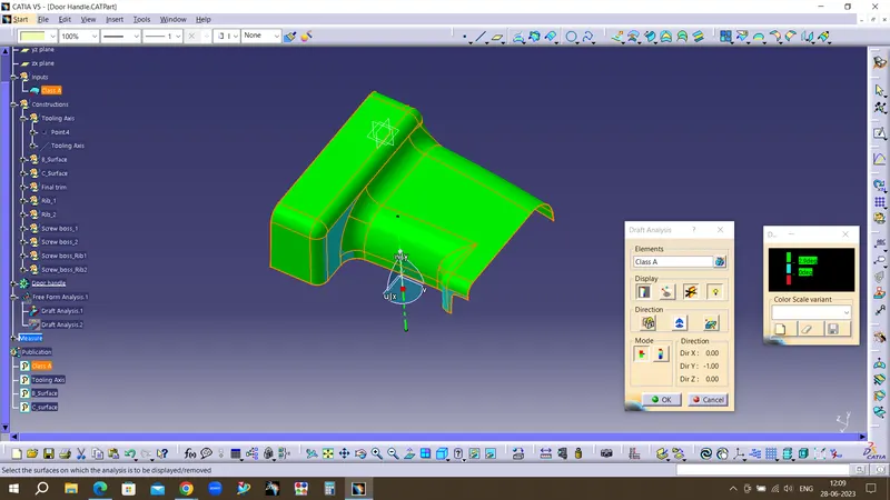
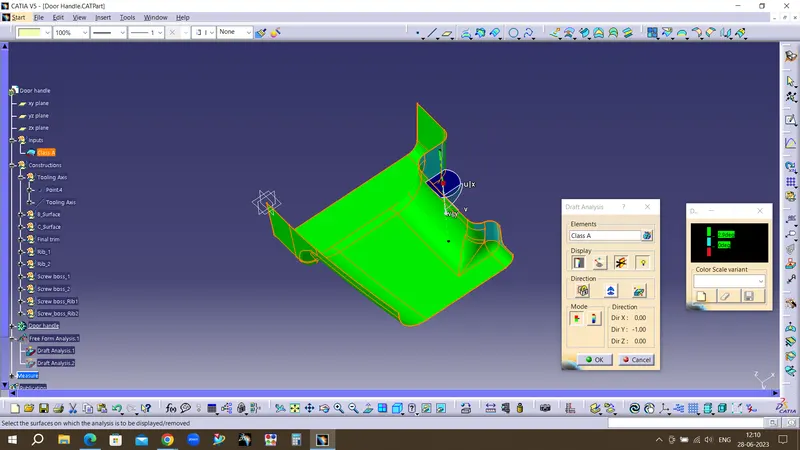
- Then lock the draft direction and perform draft analysis by clicking on the component
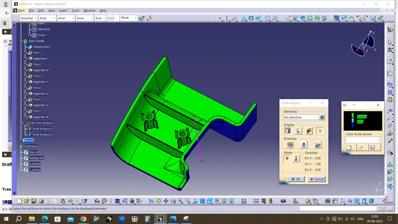
- The green colour shows the positive daft tooling direction and the given surface passes the draft analysis.
- Click on the analysis under the running point to check the draft analysis on the individual faces. It shows how much draft on specific points when we move the cursor point.
SURFACE-B CREATION
Class-B surface means thickness of a part it is not visible and is inside part. In other words, Class-B surface is a surface below a certain thickness from the class-A surface. This is the surface that contains engineering aspects of a model.
- Offset the class-A surface to 2.5mm inward direction.
- After offset ,There will be some open patches in the fillet area ,Found an open patches as shown in below images.
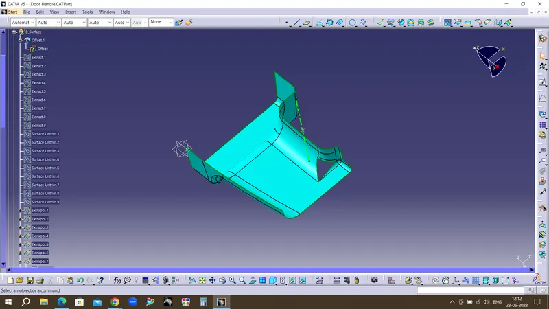
Procedure for rework on the patches and discontinuity of the offset surfaces using the features like Boundary, extract, multi-extract,extrapolate,Trim and edge fillet.
First extract the flat surfaces
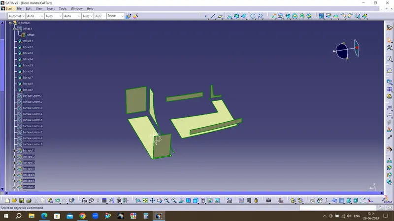
Second untrim the extacted surfaces
Third extrapolate the each surface by keeping curvature continuity and propogation mode as point continuity
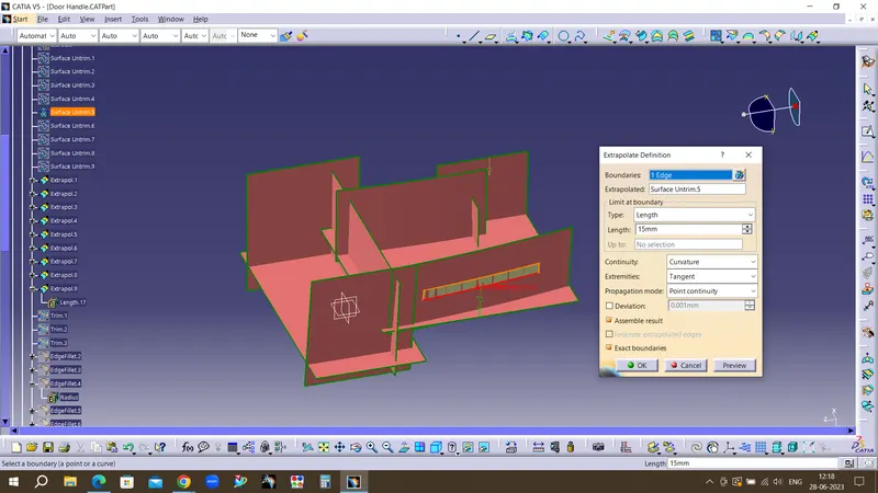
Carefully select the surfaces to trim by using offsetted surface for color matching it
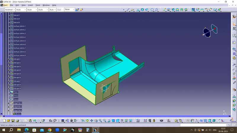
Final trim surfaces
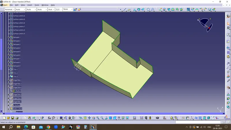
Applying fillet radius
To find the radius ,the radius surface has been extracted and untrimmed from the class A surface and thus raius value is obtained by measuring tools.
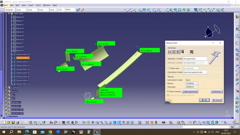
- Finally, the required corners have been filleted by even wall thickness to avoid the mould flow marks.
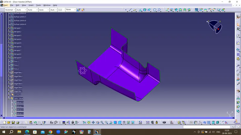
B_Surface
- To ensure the continuity of the Class-B surfaces check the boundary command to find out the boundary.
- Hence class-B surface creation is done.
Creation of C Surface
- Surface that joins class-A and class-B surfaces is class-C surface. Class C is often specified for interior surfaces not readily visible, surfaces that will be covered by another part when assembled
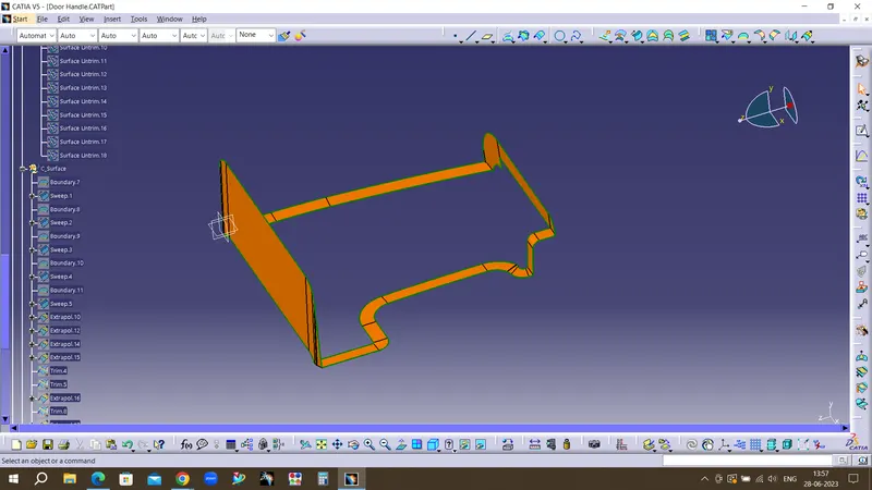
- Since it is a complex class-A surface with several sharp corneres, we cannot simply create the class-A boundary curve and sweep it at one shot.
- Hence, we need to create smaller boundary and then create sweep.
- If the surface is perpendicular to the tooling axis we have to provide 3 degree draft with reference to the tooling direction.
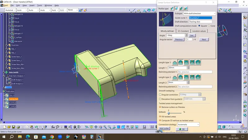
- The surface which is parrallel to the tooling axis we have to provide 90 degree with reference to the surface option.
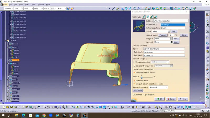
Final part of C surface
After sweep creation we have to extrpolate and trim the sharp corners to make it into single trim.
Creating the final surface of Door handel
- First step is to join the CLASS-A surface with CLASS-C surface.
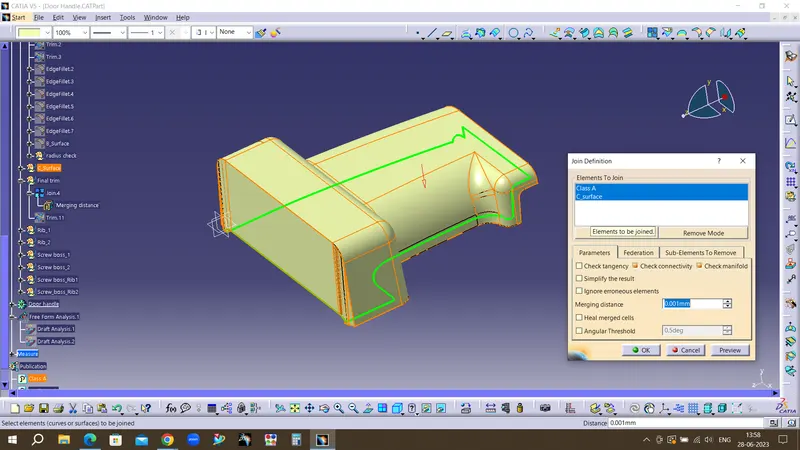
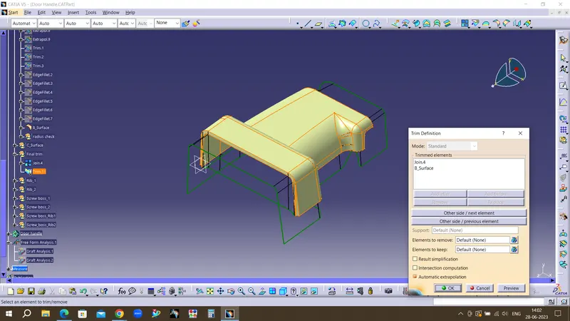
- Then Trim the Joined surface with CLASS-B surface to achieve the final Door handle surface.
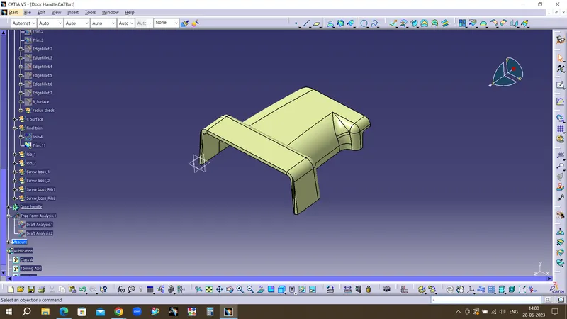
Go to the part design work bench and using the close surface command create the door handle solid part body
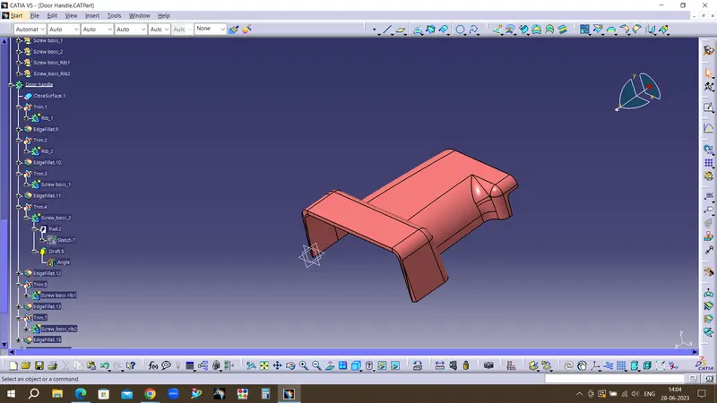
Creation of Engineering features in B surface
Ribs
Rib provides an economical way to increase stiffness and strength to the mould parts without increasing the overall thickness of the wall. It is thin protrusion that extended perpendicular from the wall.
Sketch workbench
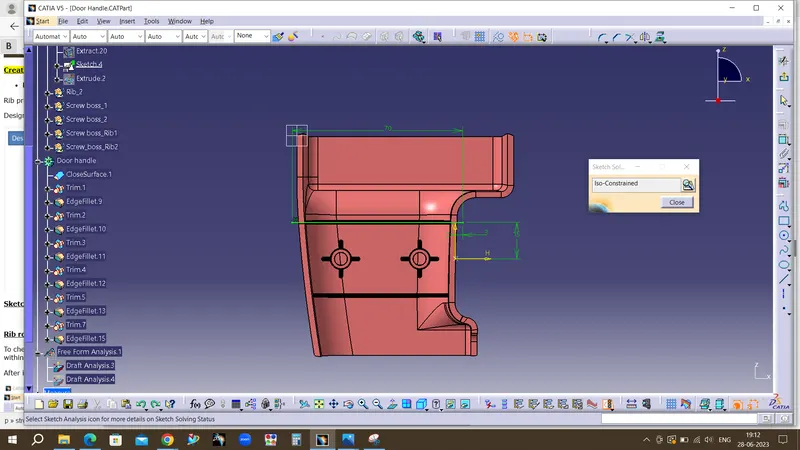
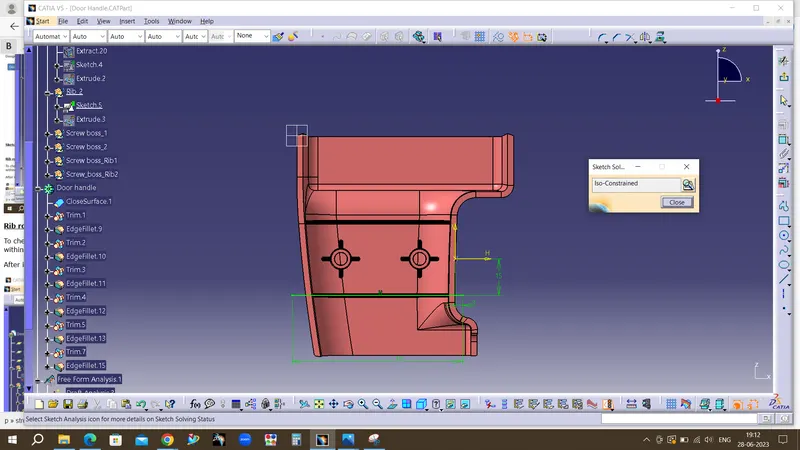
Rib root thickness analysis
To check the Rib root thickness, first take perpendicular intersection across the body and the Rib and then have to sketch a circle which tangent to the Rib base or root area by using tritangent type circle. The value must be within 30% greater of the wall thickness.
After intersection creation .Select circle - In circle type -tritangent-In element 1 -right click and select create extract-select three elements as same.
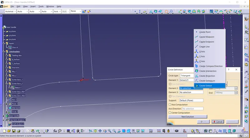
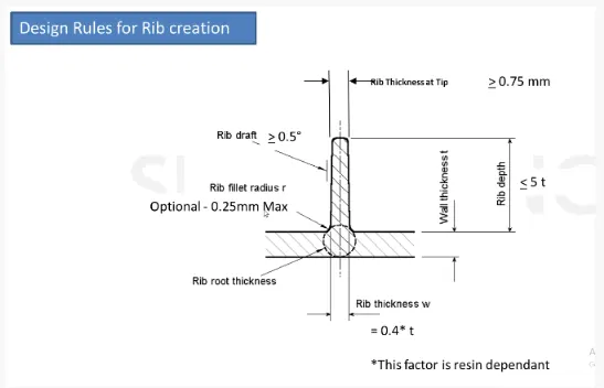
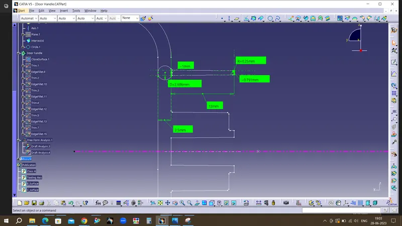
The values obtain are
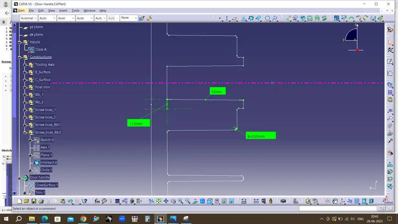
- Wall thickness = 2.5 mm
- Rib thickness w (0.4 x t) =1mm
- Minimum radius = 0.25mm
- Rib depth (5t) = 12mm
- Rib draft = 0.5 degree
- Rib thickness at tip =0.79 mm
- Rib root thickness is D=2.68 which is greater whithin 30% of the wall thickness.
Screw Boss
-
Screw boss are used as a point for attachment and assembly, most common in as cylindrical projection with hole design to receive screw or other types of fastening hardware.
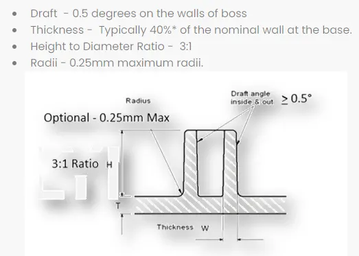
Sketch workbench
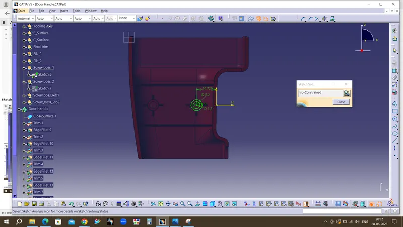
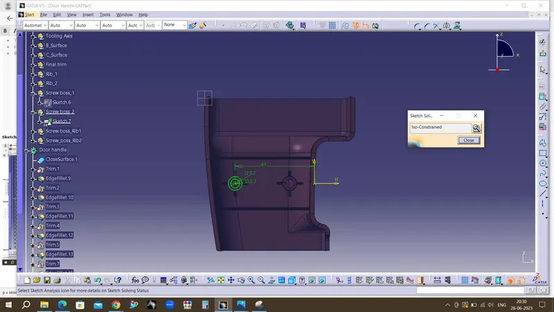
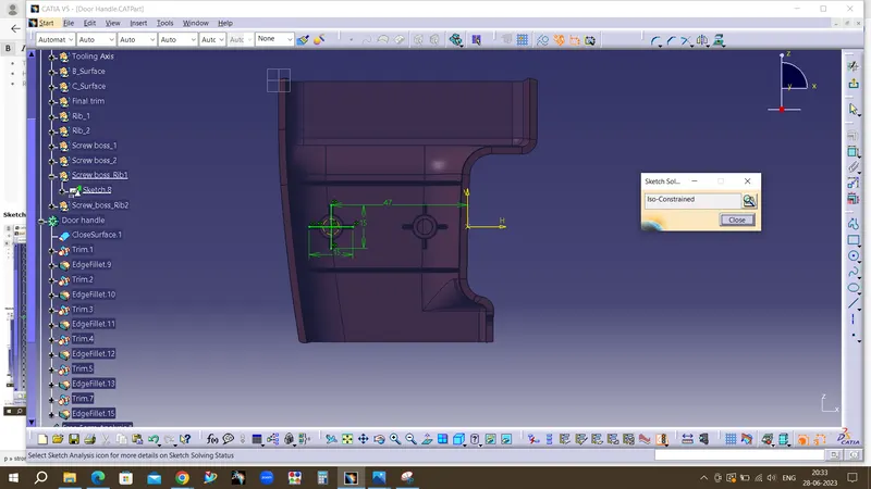
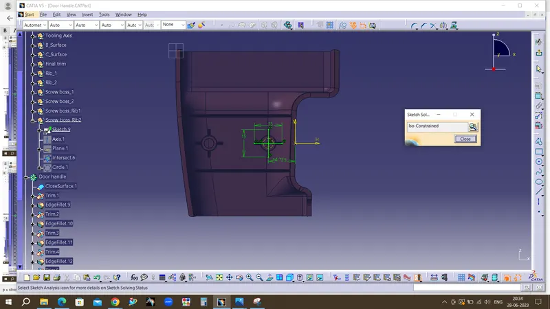
Values obtained
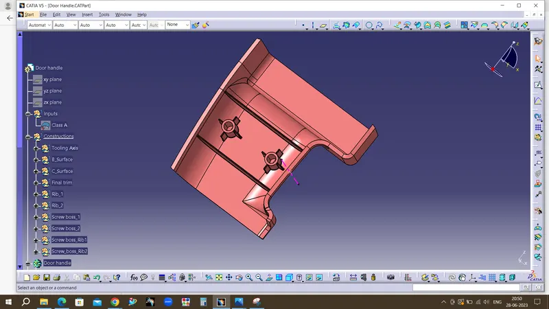
Draft Analysis for final body
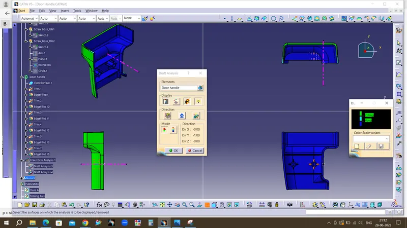
Tree Specification
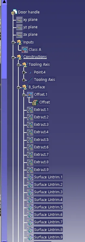
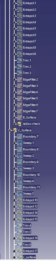
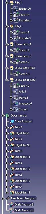
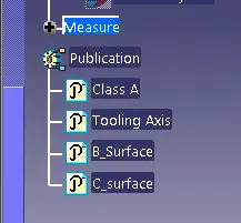
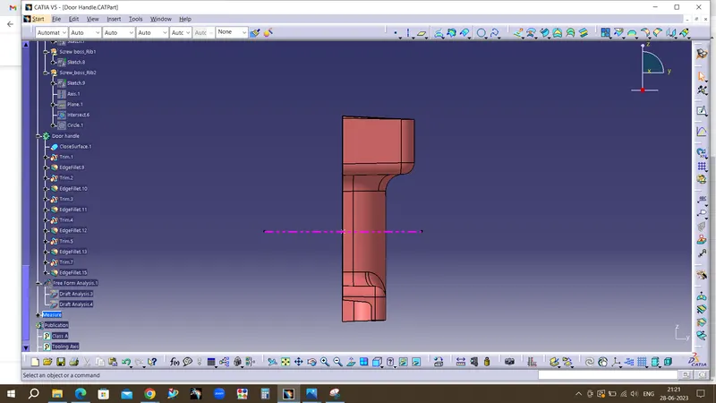
Different views
Front view
Top view
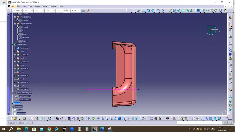
Side views