Week 10 - Challenge 1- Attachment Feature Creation (Ribs & Screw Boss)
AIM:To create Rib and Screw Boss to the given Door Handle.From the Class A create the tooling axis,Class B and perform the draft analysis on the model.
OBJECTIVE:
- To create a tooling direction.
- To perform draft analysis for given Class A-Surface .
- To design the B-Surface and C-Surface using the given Class-A surface.
- Take the Thickness of the component to be 2.5 mm.
- To create Rib and Screw Boss.
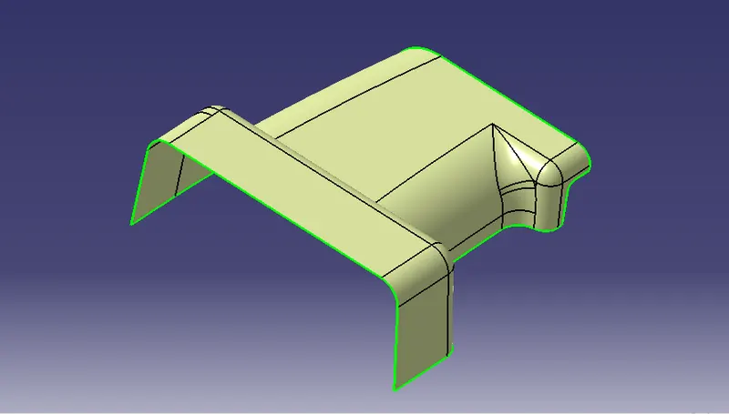
- CLASS A SURFACE
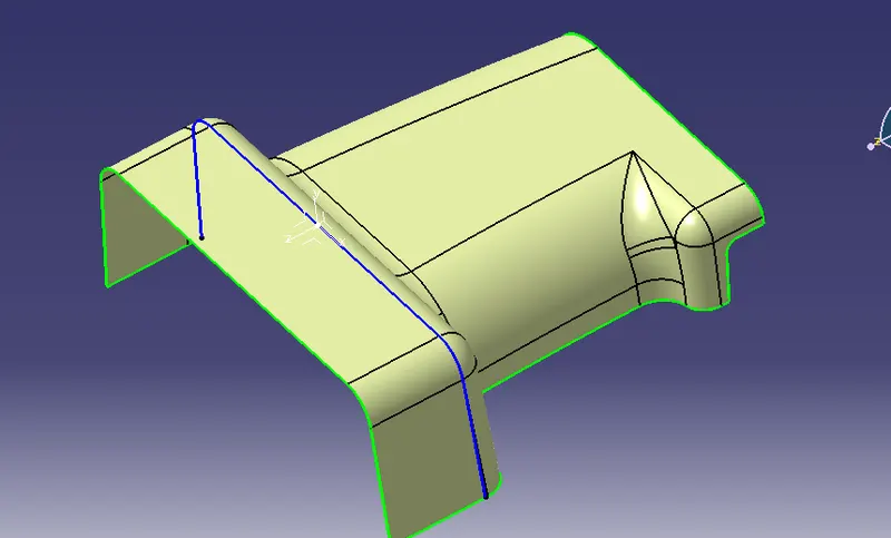
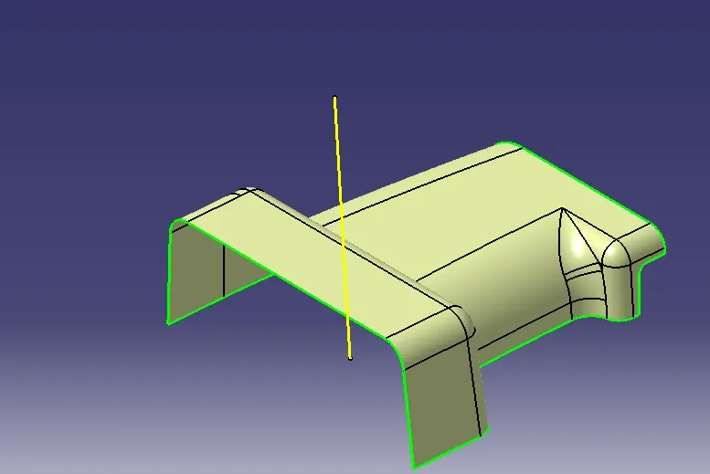
TOOLING AXIS:
observe the given class-A surface and find the proper surface to create Tooling axis,
- Create a axis system on the proper surface
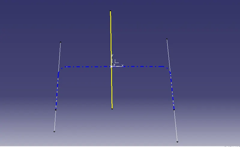
- Intersect class A with XY
- create the reference line or axis from the Z-direction using the sketch and bisect line
DRAFT ANALYSIS:
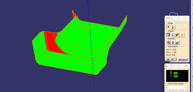
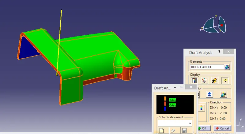
Draft analysis for the given CLASS-A surface,
Draft analysis is done after determining the tooling axis, draft analysis is used to check whether the minimum draft (3 degrees) is maintained or not.
- Open the featured draft analysis tool.
- Drag and align the compass on the Tooling axis.
- Lock the draft direction and perform draft analysis by clicking on the component.
- CLASS B SURFACE
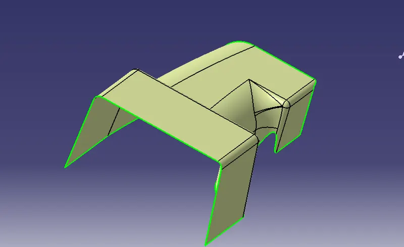
Class B Surface is created With the help Class A Surface
- Offset the class-A surface to 2.5mm inward direction.
- Remove patches and discontinuity of the offset surfaces using the features like extract, multi-extract,Un trim, extrapolate.
- Provide proper Fillets.
- To ensure there is no gap in Class-B surfaces ,check the boundary command to find out the boundary.
- CLASS C SURFACE
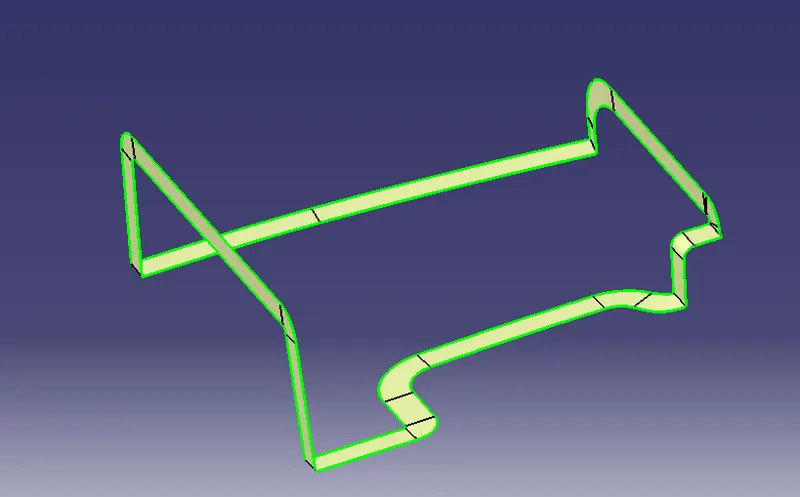
Class C is created with help of A-Surface,The Surface that joins class-A and class-B surfaces.
- Create the Boundary
- Sweep at 90 degree.
- Extrapulate.
- Trim off the sweep surfaces.
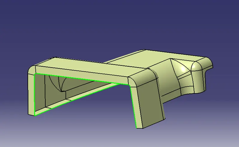
JOIN CLASS C WITH CLASS A
- FINAL TRIM
Trim the Joined surface with CLASS-B surface to achieve the final Out put.
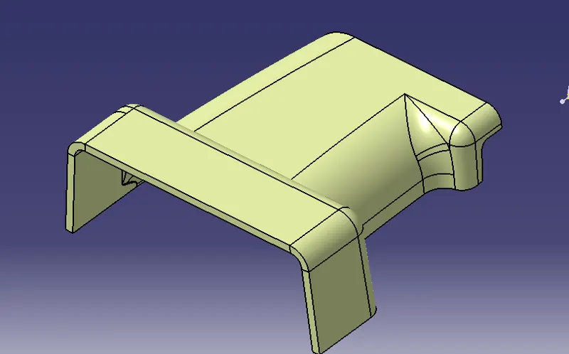
In part design work bench and using the close surface command create the part as solid part body.
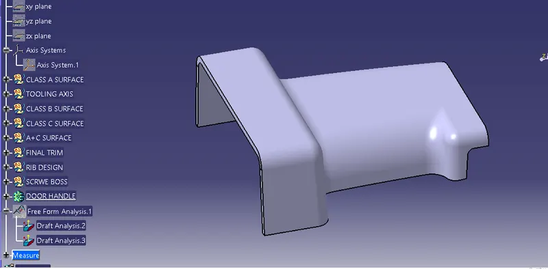
CREATION OF RIB & SCREW BOSS:
- RIB
Rib provides an economical way to increase stiffness and strength to the mould parts without increasing the overall thickness of the wall.It is thin protrusion that extended perpendicular from the wall.
Design considersation of the Rib
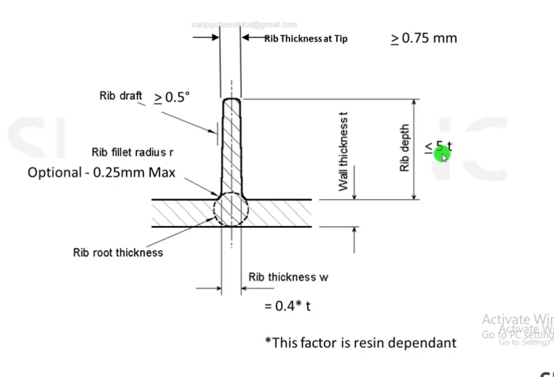
Creation of RIB,
- To Create Sketch, Extract one surface and position there.
- Extrude it 12.5mm.
- Thick surface 1mm.
- Draft it .
- Fillet the Edges.
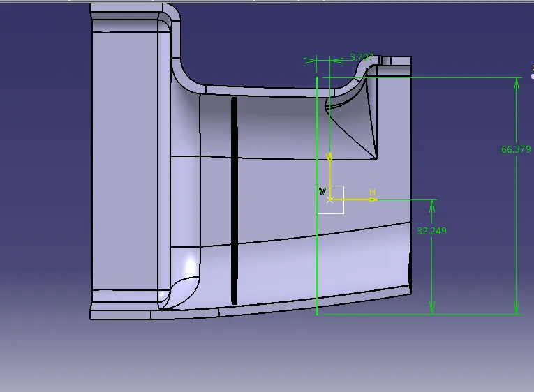
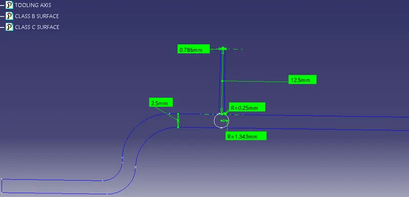
Rib root thickness analysis
To check the Rib root thickness,
- To take perpendicular intersection across the body.
- sketch a circle which tangent to the Rib base using tritangent type circle.
- The value must be within 30% greater of the wall thickness.
- SCREW BOSS
Screw boss are used as a point for attachment and assembly, most common in as cylindrical projection with hole design to receive screw or other types of fastening hardware.
Design considersation of the Screw boss,
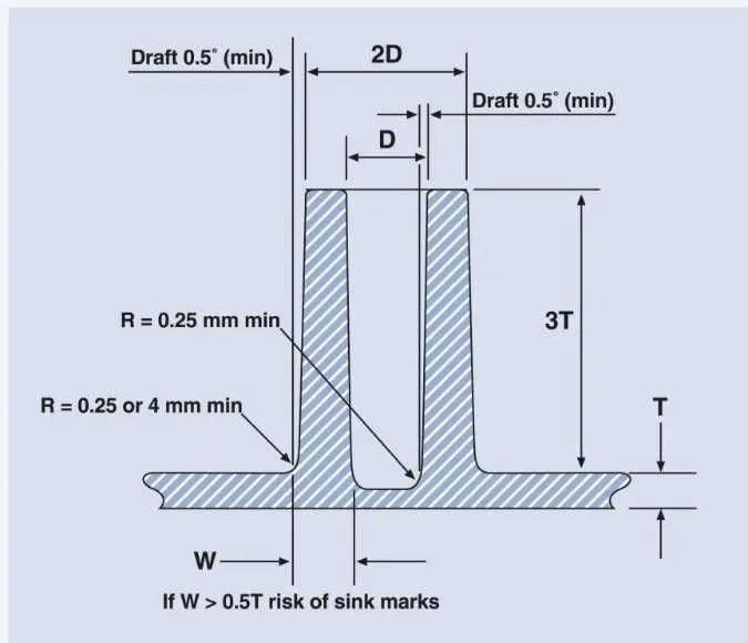
- To Create the Sketch.
- Pad the Sketch.
- Draft it .
- Fillet the Edges.
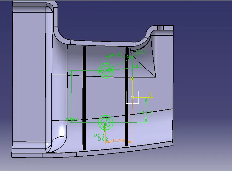
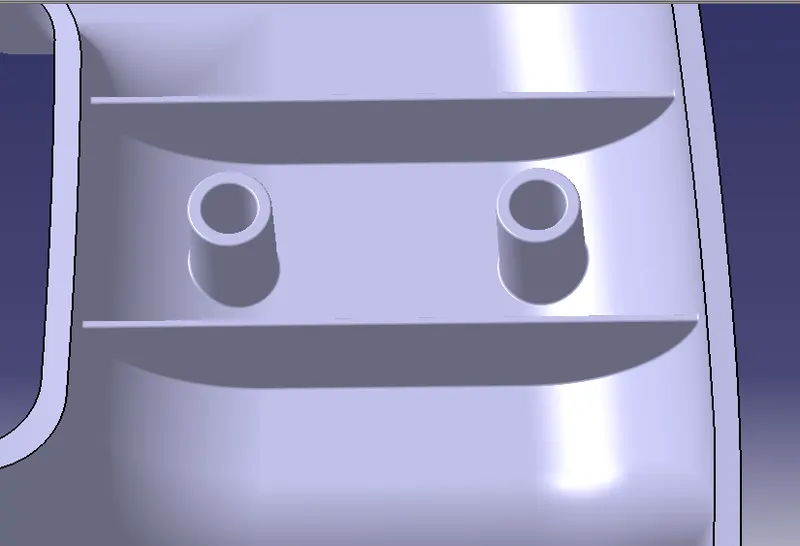
FINAL OUTPUT
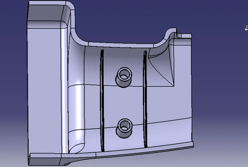
DRAFT ANALYSIS:
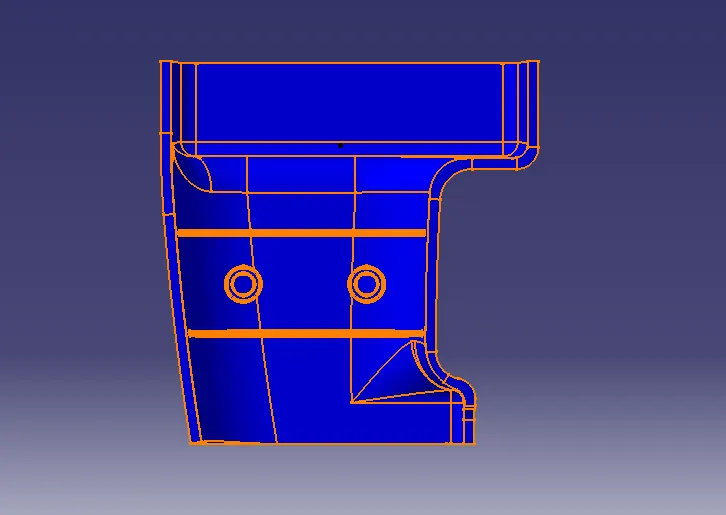
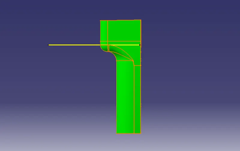
On final Body,
- Change the view mode to Material Mode.
- Align the Compass with Tooling axis.
- Lock the draft direction and perform the Draft analysis.
CONCLUSION:
Hence design the Rib and Screw boss as per the rules and Perform Draft analysis for the final component .