Week 10 - Challenge 1- Attachment Feature Creation (Ribs & Screw Boss)
RIBS AND SCREW BOSS DESIGN
AIM
Create the component through the given Class-A surface.
The tooling axis for the given Class-A Surface should be created meeting the requirements of the draft angle and at the end perform the Draft analysis on the model. Create the rib and screw boss as by considering the design rules
CLASS A SURFACE
In automotive design, a class A surface is any of a set of free form surfaces of high efficiency and quality. It gives the aesthetic of the component which is created by the styling team and gives to the part design engineer to create the part with all engineering aspects.
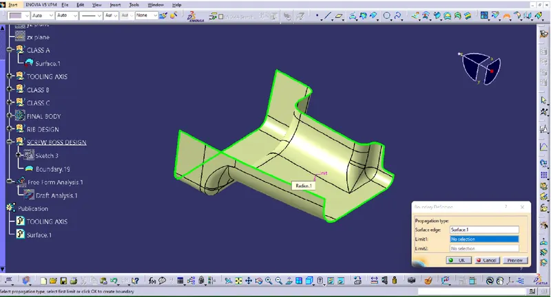
We have been given the Class-A surface and the first thing to do is to make sure that the given surface has no gap in between them. We can check that either visually or by using the boundary command.
TOOLING AXIS
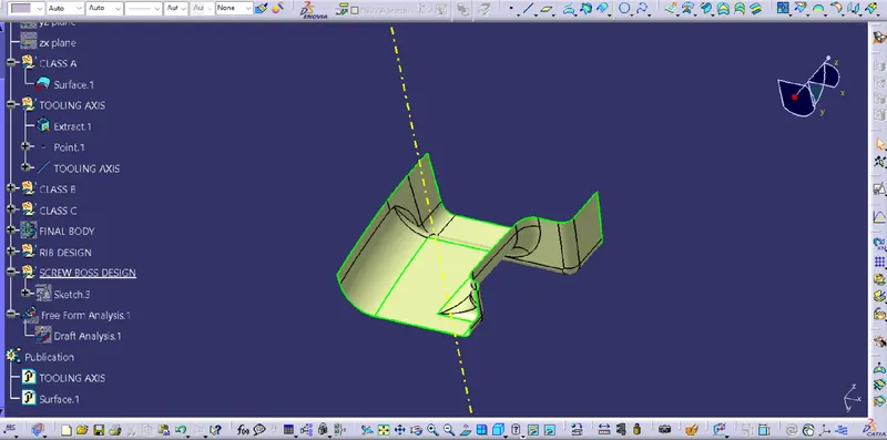
TOOLING AXIS is created by bisecting the axis created on two intersections. The best tooling direction for the class-A surface is along y-axis direction. Flat surface on the center part is extracted for creating the tooling axis in y-direction. Then created a line with the point and direction along y-axis.
DRAFT ANALYSIS OF CLASS A SURFACE
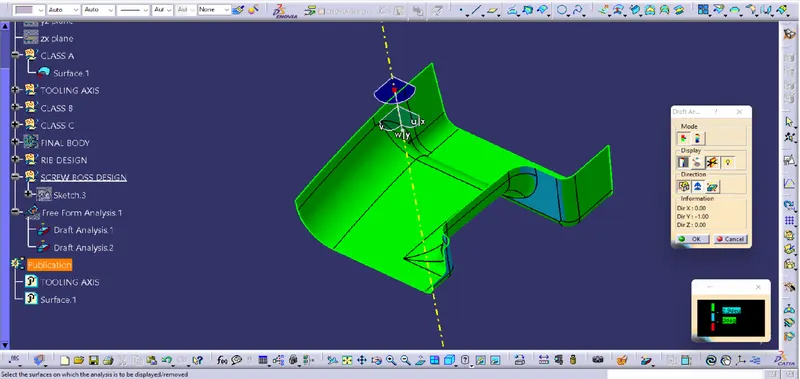
Change the view to matereial mode for draft anlysis.draft analysis is done using featured draft analysis tool.
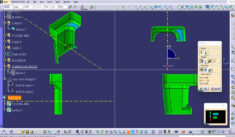
CLASS B SURFACE
Class-B surface means the thickness of a part it is not visible and is inside part. In other words, the Class-B surface is a surface below a certain thickness from the class-A surface. This is the surface that contains engineering aspects of a model.
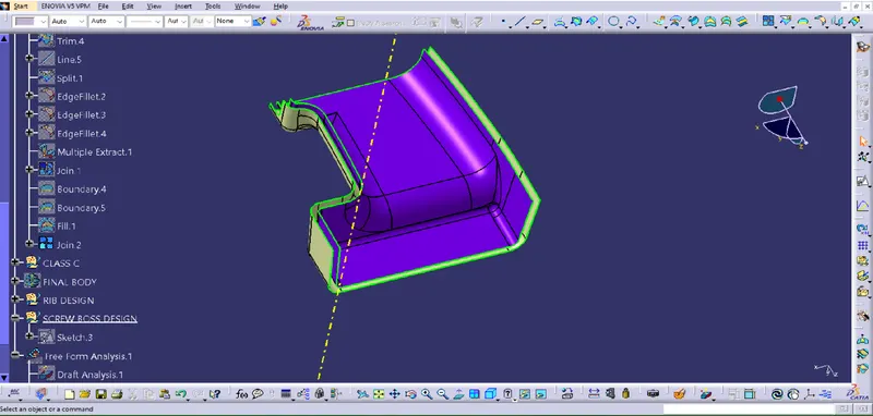
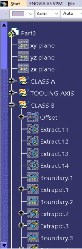
B SURFACE is created by Offseting the class-A surface to 3mm inward direction. Patches are created while offsetting the surface.
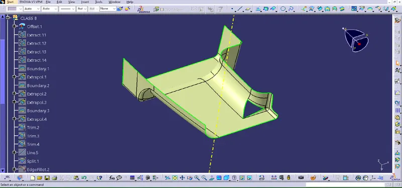
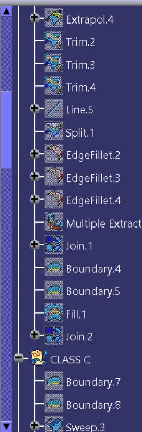
Rework on the patches using the features like extract, multi-extract, sweep, multi-section surfaces, extrapolate.
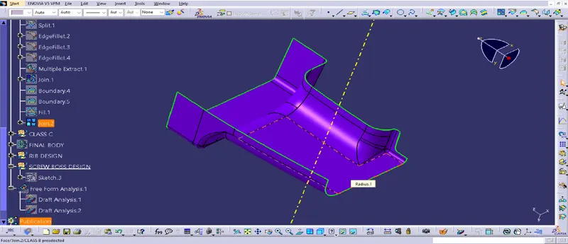
the boundary command is used to identify and highlight the patches.If there is no inner boundaries present then the CLASS B surface is created.
The surface that joins class-A and class-B surfaces are class-C surfaces. Class C is often specified for interior surfaces not readily visible.
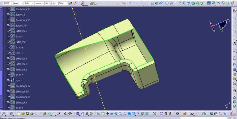
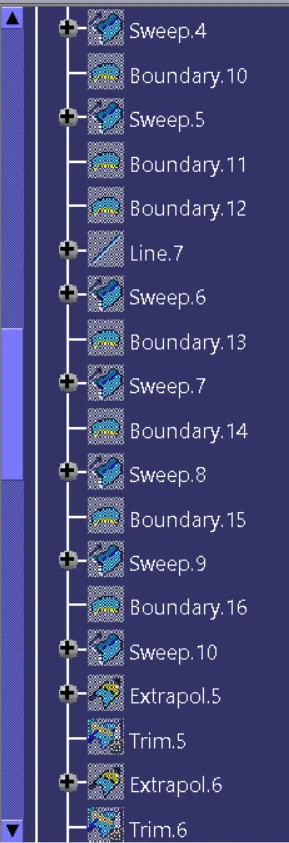
The method used for class c surface is sweep feature
Since it is a complex class-A surface, we cannot create the class-A boundary curve and sweep in a single stretch .
small sections are created using multi-extract command and then create sweep of 90 degree with reference to the surface option.
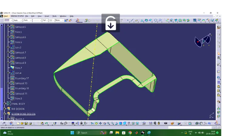
SOLID SURFACE
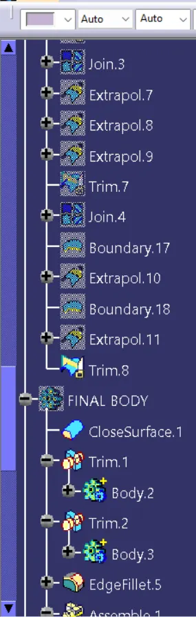
CLASS A and CLASS C is Join together
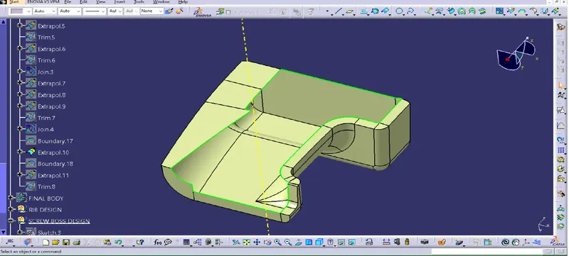
CLASS B is trimmed with CLASS A AND C
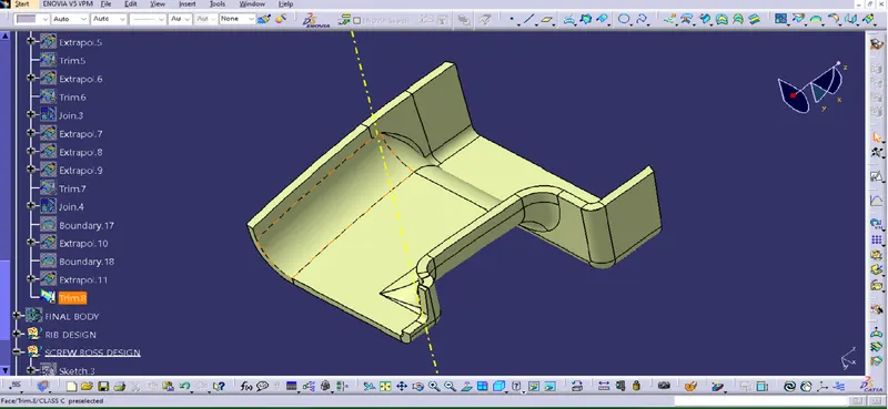
GEOMETRICAL TREE STRUCTURE
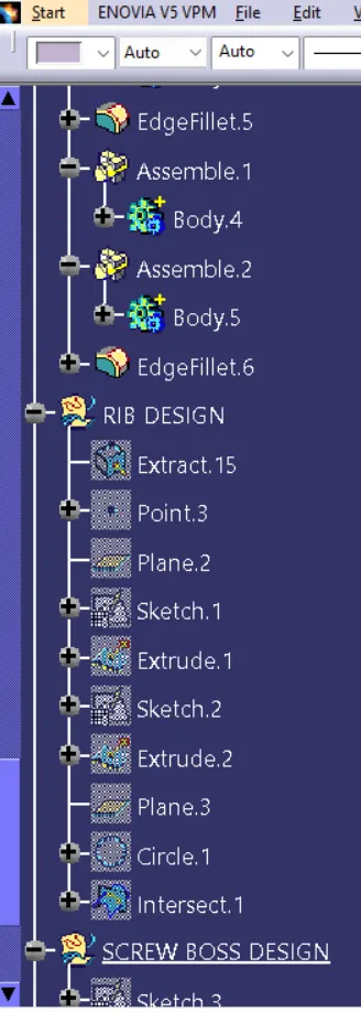
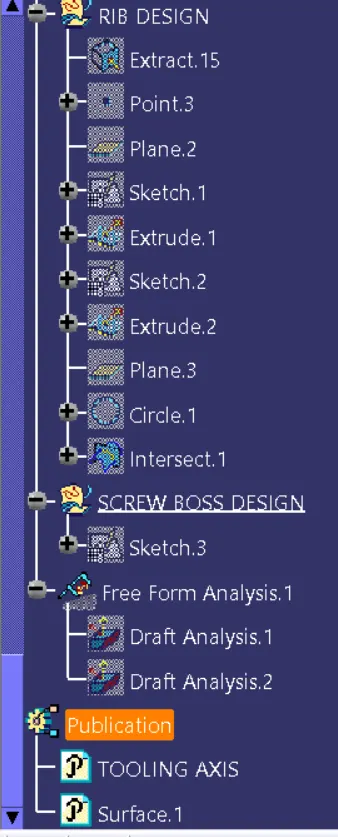
PART BODY
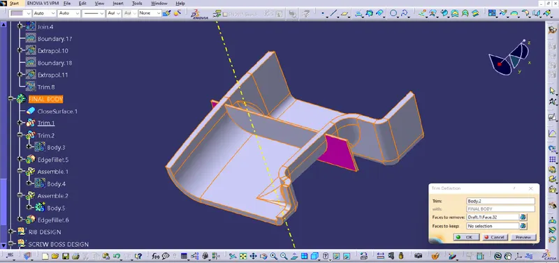
Close Surface feature usedto make a solid body from the surface.
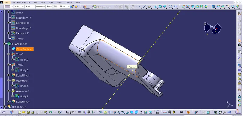
RIB DESIGN
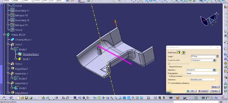
SCREW BOSS DESIGN
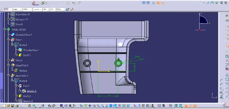
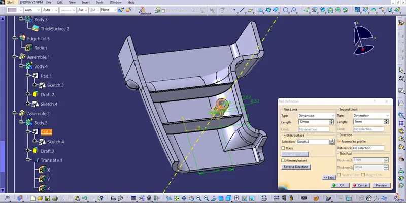
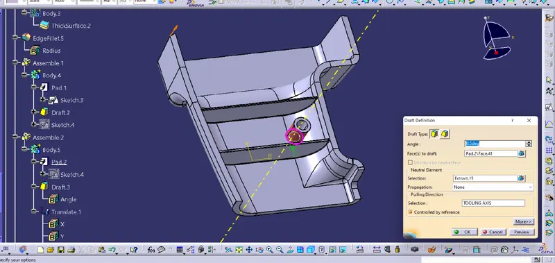
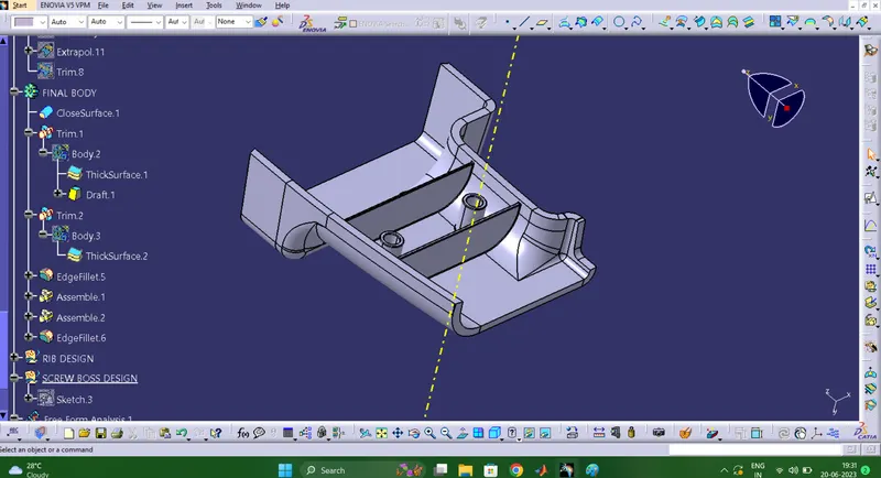
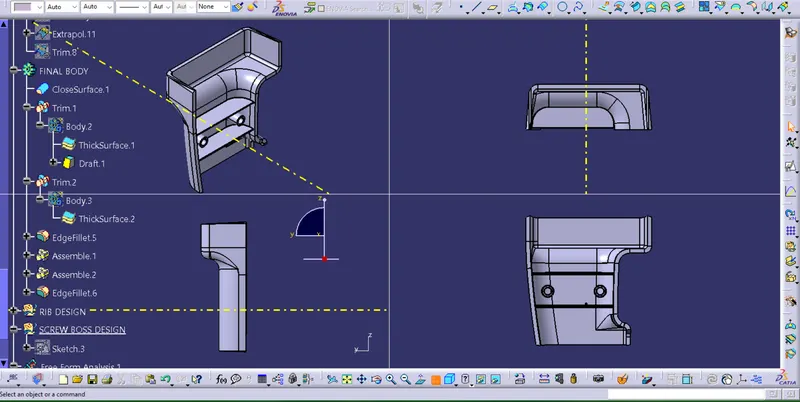
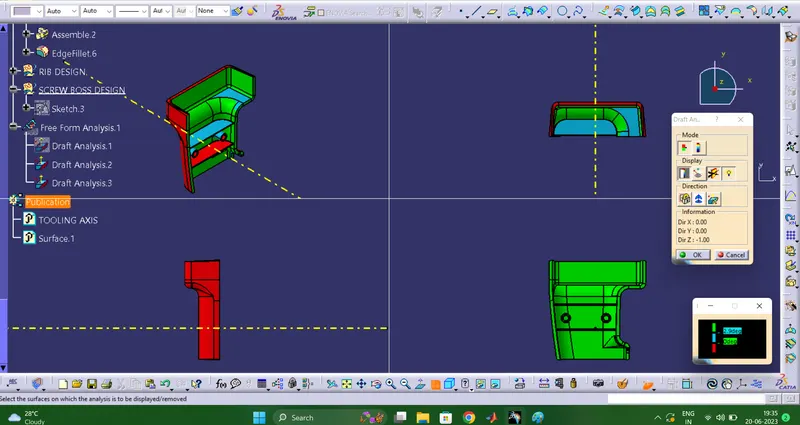
DRAFT ANALYSIS OF COMPONENT
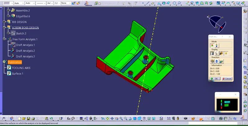
Change the view to material mode for draft anlysis
draft analysis is done using featured draft analysis tool
Use the compass fucnction to aling the compass to the tooling direction and lock the direction using lock function in the draft analysis tool bar
the surface is showing green colour so that the surface clears the minimum draft angle of 3 degree
By using the analyses under the running pointwe can check draft angle on the individual faces. It shows how much draft on specific points when we move the cursor point.