Week 10 - Challenge 1- Attachment Feature Creation (Ribs & Screw Boss)
AIM:- To create the rib and screw boss for the door handle considering the design rules for the rib creation and screw boss creation and then perform the draft analysis for class A and final cmponent.
Objectives:-
- Creating a tooling axis using bisecting method.
- Performing draft analysis for Class A and final component.
- Creating Class B and Class C surface and finally join them to get a closed surface.
CLASS A SURFACE:- Following surface is given as the input for the component creation.
To continue design first we need to create a tooling axis for class A surface.
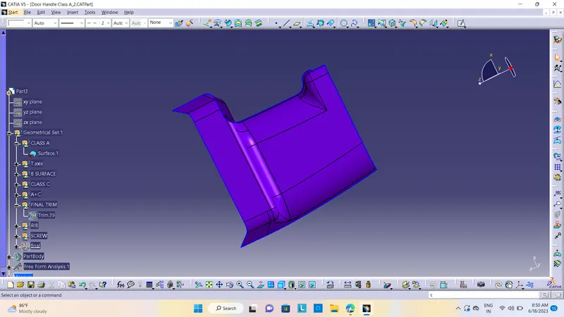
Tooling axis creation :
The first step is to observe the given class-A surface deeply and we can say the larger flat area which is perpendicular to the Tooling axis. So, by considering this thing for this class-A surface tooling direction will be in the Y-direction. so we create the point on the flat surface as shown in the figure.
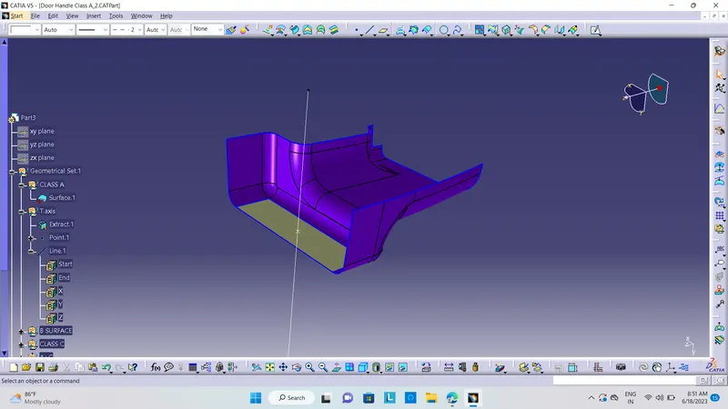
DRAFT ANALYSIS OF CLASS A SURFACE:-
DRAFT ANALYSIS RESULT ARE SHOIWN BELOW-
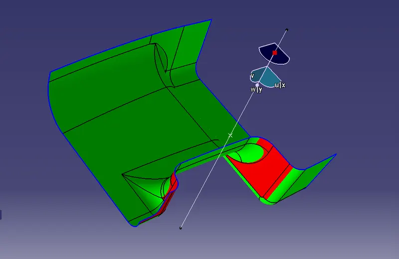
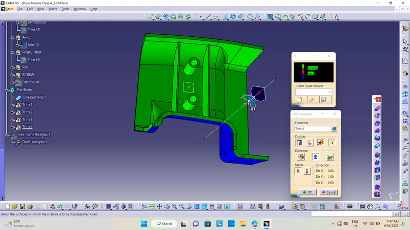
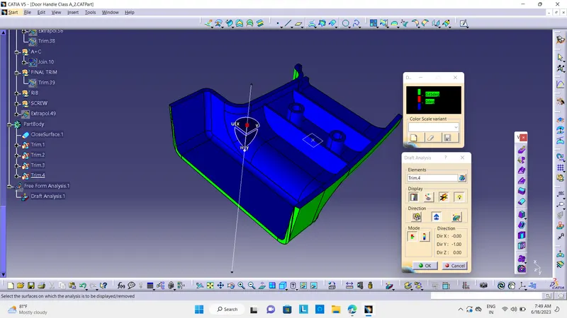
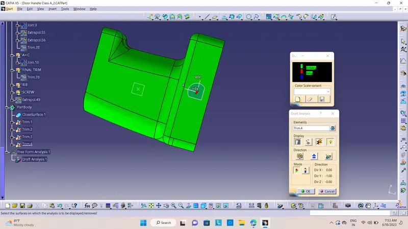
The Draft Analysis command enables you to detect if the part you drafted will be easily removed. This type of analysis is performed based on color ranges identifying zones on the analyzed element where the deviation from the draft direction at any point, corresponds to specified values.
CREATION OF CLASS B SURFACE :-
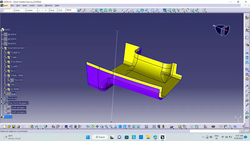
- Offset the class A surace with the given thickness and fill the patches present in offset surface using different commands.
- Extrapolate the boundary surfaces of Class B surafce for trimming.
Purple colour shows the Class B surface and YELLOW colour shows the Class A surafce.
surfaces to 2.5 mm to create the thickness.
CREATION OF CLASS C SURFACE :-
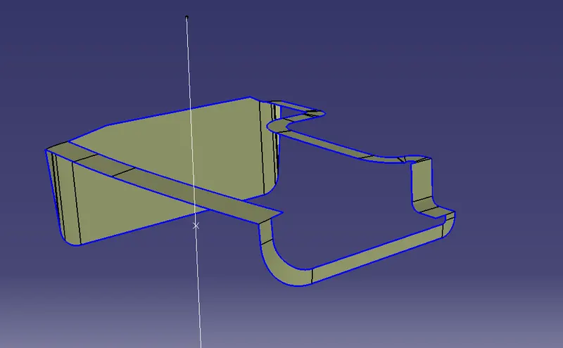
- Create the boundary of class a surface and make a surface using sweep and mulisectionn command.
- then join all the corners and c surfaces.
- Unhide the A Surface to Take a boundary as a reference to make C surface.
- Go to sweep line-> with Reference Surface 87 degree draft angle for all sweep.
- And join all the sweep parts to make a Class C surface.
- Then Publicize it.
CLASS A + CLASS C SURFACES:-
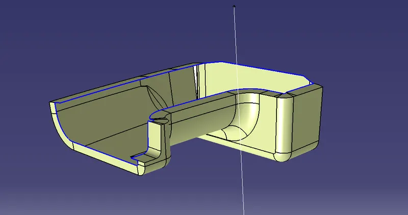
- Now trim the Class A surface and CLASS C surfaces together to make it a single surface.
CLASS A +CLASS C + CLASS B SURFACES :-
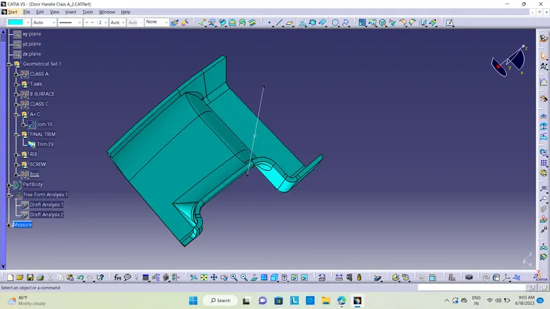
- Finally, Trim the joined class A and Class c surafce with class B surface to get the final component
- Now, go to part design workbench and using close surface command make it a solid component.
RIB CREATION:-
- Create a sketch on zx plane and extrude it according to design rules .
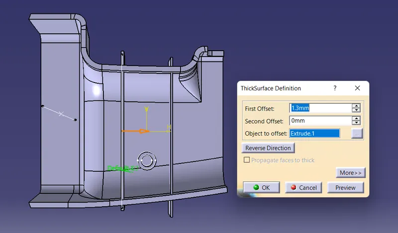
- Now use the thick surface command to give the thickness.
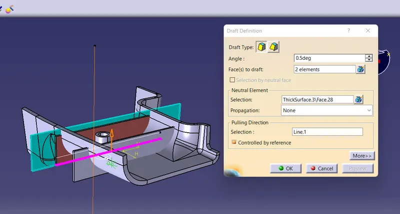
- Give the draft on both thickened surfaces.
- Use the union trim to give the required shape and assemble it with final component.
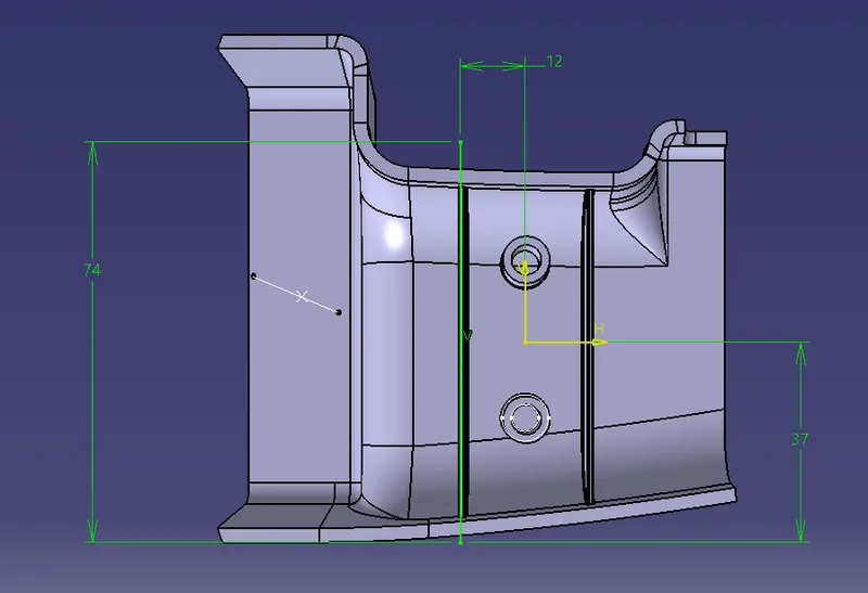
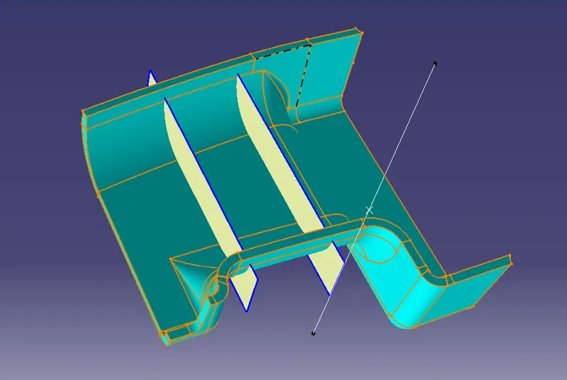
Thickness 1.3 show the below
draft value 0.5
SCREW BOSS CREATION:-
- Sketch the profile of screw bosses on top plane.
- use extrude command for height.
- Give the draft on inside and outside surfaces
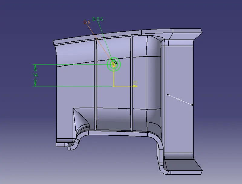
- Rib
Rib provides an economical way to increase stiffness and strength to the mould parts without increasing the overall thickness of the wall. It is thin protrusion that extended perpendicular from the wall.
Design considersation of the Rib
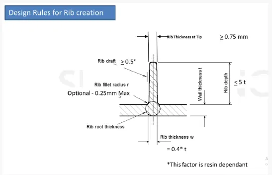
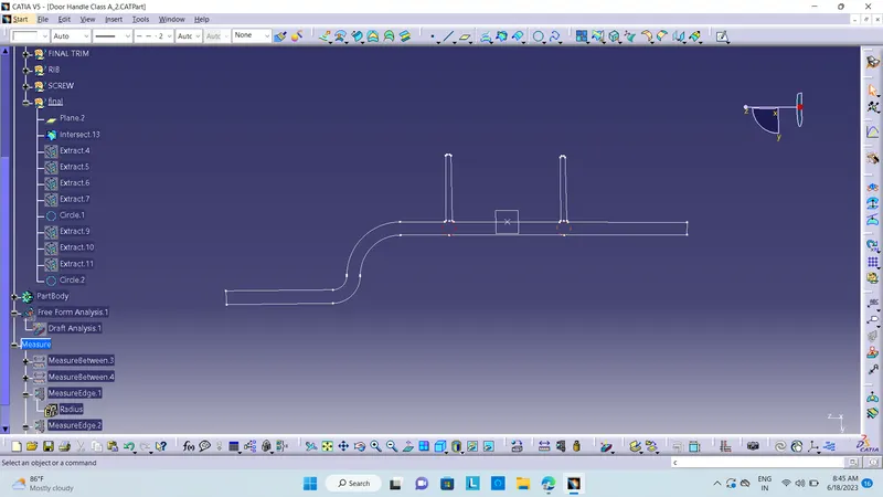
Rib root thickness analysis
To check the Rib root thickness, first take perpendicular intersection across the body and the Rib and then have to sketch a circle which tangent to the Rib base or root area by using tritangent type circle. The value must be within 30% greater of the wall thickness.
DRAFT ANALYSIS OF FINAL COMPONENT :-
- Draft analysis of rib and screw boss-
Conclusion :
Hence the Rib for the drill handle considering the design rules for rib creation and Screw boss creation and Draft analysis is also performed for the final component is successfully done.
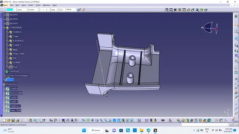
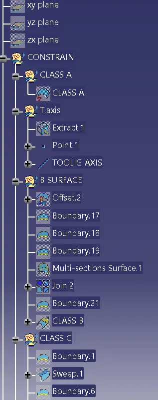
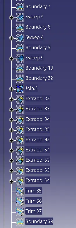
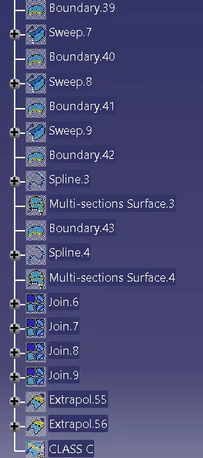
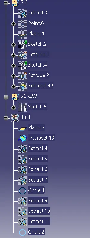
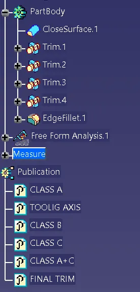
TREE SECTION