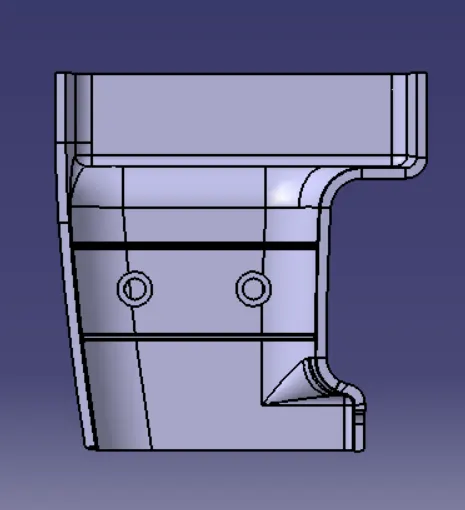
Week 10 - Challenge 1- Attachment Feature Creation (Ribs & Screw Boss)
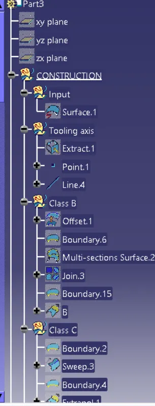
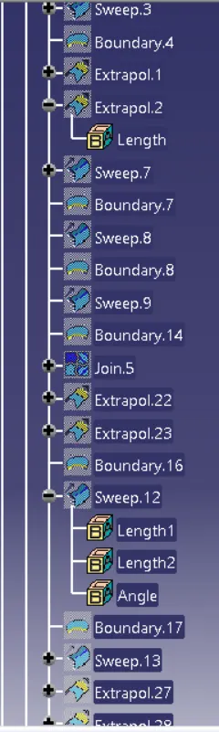
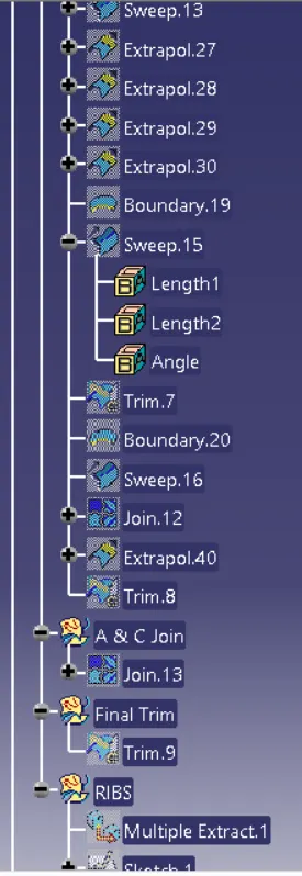
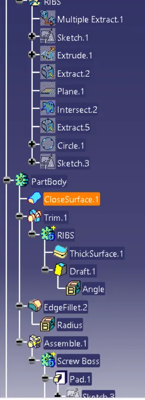
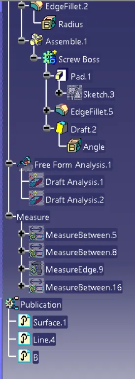
The feature tree of door handle
OBJECTIVE:
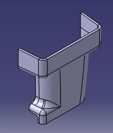
Create Closed Body for given Door Handle Class A surface and also, Create the Rib & Screw Boss for the Door Handle considering the design rules.
RIBS
Ribs are used to strengthen the walls of your mould without increasing wall thickness
SCREW BOSSES:
- Screw Bosses are typically used to assist in assembly, as a receptacle for a screw or threaded insert or as the locator.
CLASS A SURFACE:
- Class A surface means Visible surface of the Component or part.
- It provides the Aesthetic Appreance to the component.
Tooling axis creation
- Arrange the view manually to check the best tooling direction which covers most of the surfaces.
- Tooling direction along Y axis can clear most of the surfaces. So we can create tooling axis along y direction.
- I have created tooling axis using normal to the surface method. For that extract a plane surface and create a midpoint on it.
- Create a line on the point and direction along y axis.
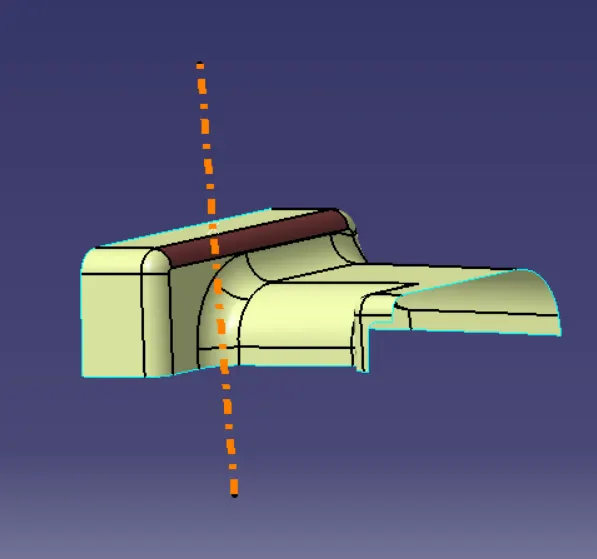
Draft analysis for class A surface:
Here its clearing in 2.9 degree
Class B surface Creation:
To create the class B surface for the door handle, I offset the class A surface to 2.5mm inside. Once the class A surface is offset created, according to the thickness, we can observe some patches on the offset surface due to the fillets on the class A surface. Now, we need to close those patches. I used multi-section solid command to close the patches.
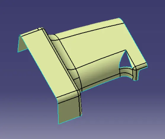
CLASS-C surface creation
Surface that joins class-A and class-B surfaces is class-C surface.
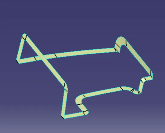
Creating Final Drill handle surface
- Join the CLASS-A surface with CLASS-C surface.
- Extrapolate the CLASS-B surface and trim it with Joined surface.
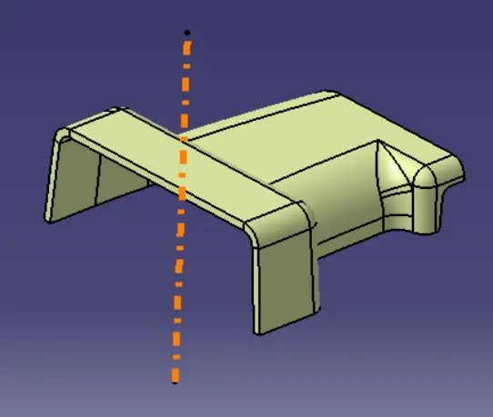
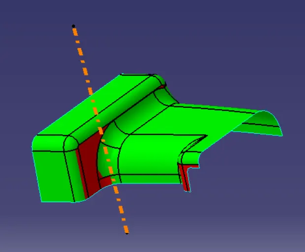
DRAFT ANALYSIS:
Here its clearing in 2.9 degree
RIB Design:
Thicken- 0.4*thickness=0.4*2.5
height- 5*thickness=5*2.5
draft= 0.5
fillet= 0.25
To create the ribs on the solid part body, we need to follow the above-mentioned design guidelines. Initially, I create a line sketch for the rib and I extruded it in the tooling axis direction and I thicken the extruded surface to 1.2mm toward the inside,
after thickening the extruded surface I gave 0.5deg of draft angle to the rib, and I union trim the rib with the part body to remove the extra surface of the rib, by union trimming the rib with the part body the rib gets added to the main part body without the unwanted extra part. After adding the rib to the part body, I gave the fillet to the rib with a radius of 0.25mm.
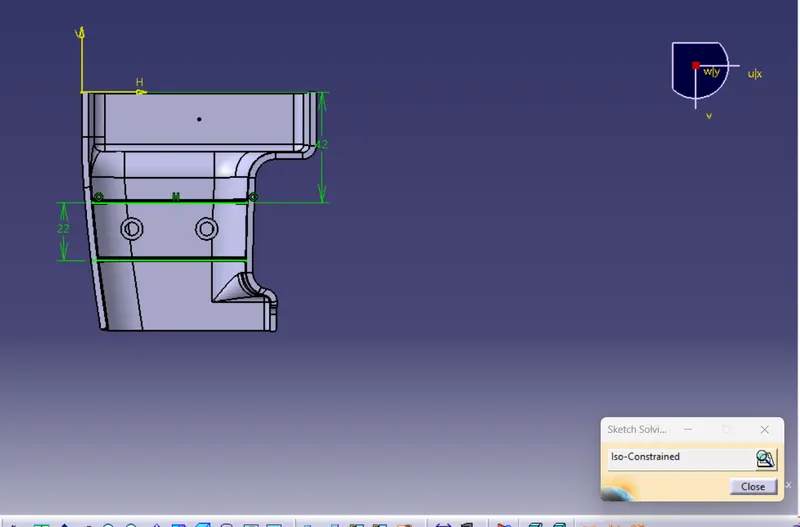
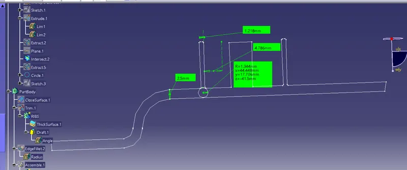
To check the rib root thickness, I created a plane which is perpendicular to the base surface (if the plane is parallel to the base surface the intersection will be taken, but we can't see any rib intersection on it, so that is why the plane is created perpendicular to the base surface). After taking the intersection for the body and plane, we need to create a tri-tangental circle at the bottom of the rib. To create the circle, we need to extract the faces of the intersection (if we directly select the faces without extracting the required faces the input may take the entire intersection surface as an input) which we need to give as input for the tri-tangental circle. The tri-tangental circle is shown below, with the measurement of it.
.
SCREW BOSS Design:
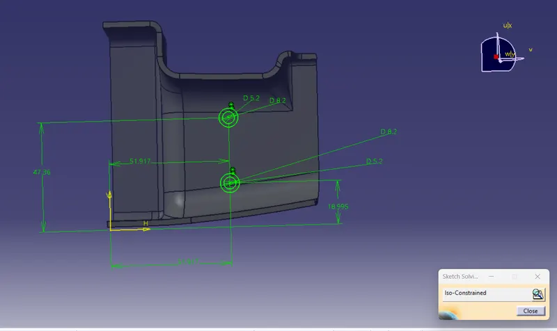
To create the screw boss, I created the circular sketch in the sketcher workbench and I padded the sketch to 12.5mm. Now, I drafted the inside and outside surfaces with 0.5deg in the tooling axis direction. After creating the screw boss, I gave 0.25mm of the fillet to all sides.