Week 10 - Challenge 1- Attachment Feature Creation (Ribs & Screw Boss)
OBJECTIVE:Create the rib for the Drill Handle considering the design rules.
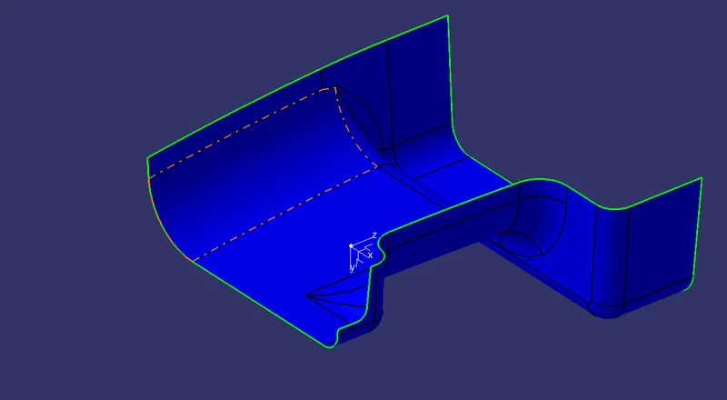
GIVEN CLASS A SURFACE:
PROCEDURE FOLLOWED:
1.TOOLING AXIS CREATION
The Tooling Direction is basically the direction that the mold pulls a part. The mold is built in two separate pieces, basically. You have a Cavity side and you have the Core side. The Core pulls apart from the Cavity and that's the Dye line or the Tooling Direction.
- Visually check the possible tooling direction .In this case y direction is the suitable tooling direction.
- A point is created at the flat class a surface and created an axis sysytem at that point.
- An inter section is made by xy plane and the given class a surface.using bisecting method create the tooling axis.
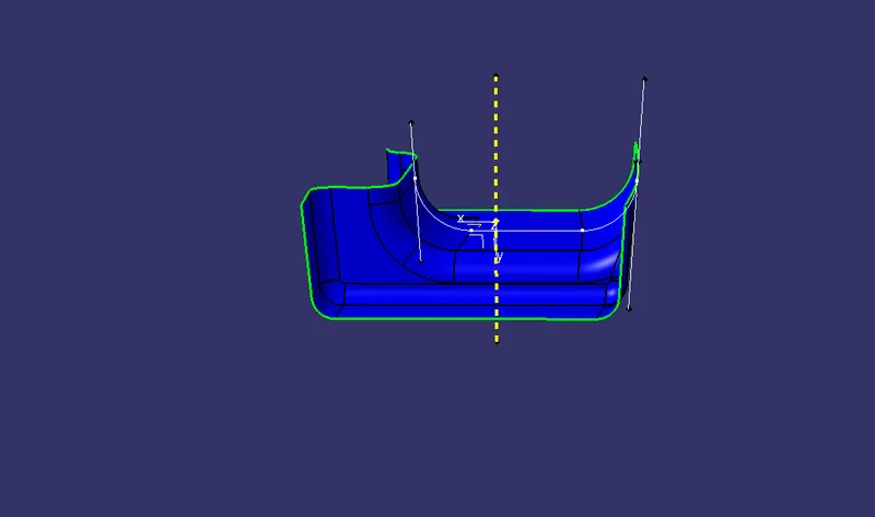
- Bisecting lines were used to get the exact medium from the two sides so that maximum positive draft angle can be achieved.
2.DRAFT ANALYSIS:
When developing parts for plastic injection molding, applying a draft (or a taper) to the faces of the part is critical to improving the moldability of your part. Without it, parts run the risk of poor cosmetic finishes and may bend, break, or warp due to molding stresses caused by plastic cooling. Equally important, an absence of draft may prevent parts from ejecting from the mold, damaging not only the parts but possibly the mold itself—a costly and time-consuming detour.
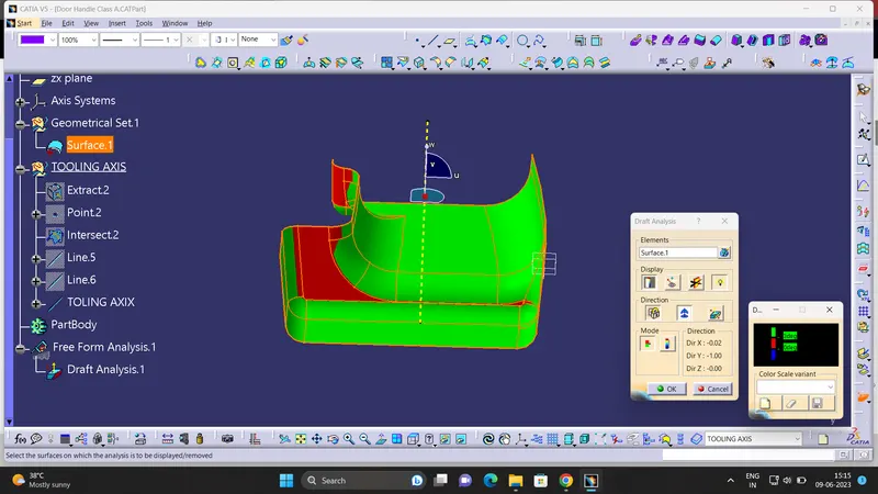
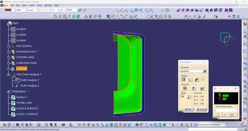
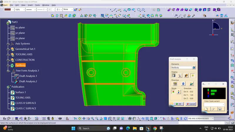
The Draft Analysis command enables you to detect if the part you drafted will be easily removed. This type of analysis is performed based on color ranges identifying zones on the analyzed element where the deviation from the draft direction at any point, corresponds to specified values.
PROCEDURE:
- First change the created part into material.
- Click on the compas and plase in the tooling direction.
- Use the lock command to fix the compass
- Click on the surface and apply the draft angle
3.CREATION OF CLASS B SURFACE:
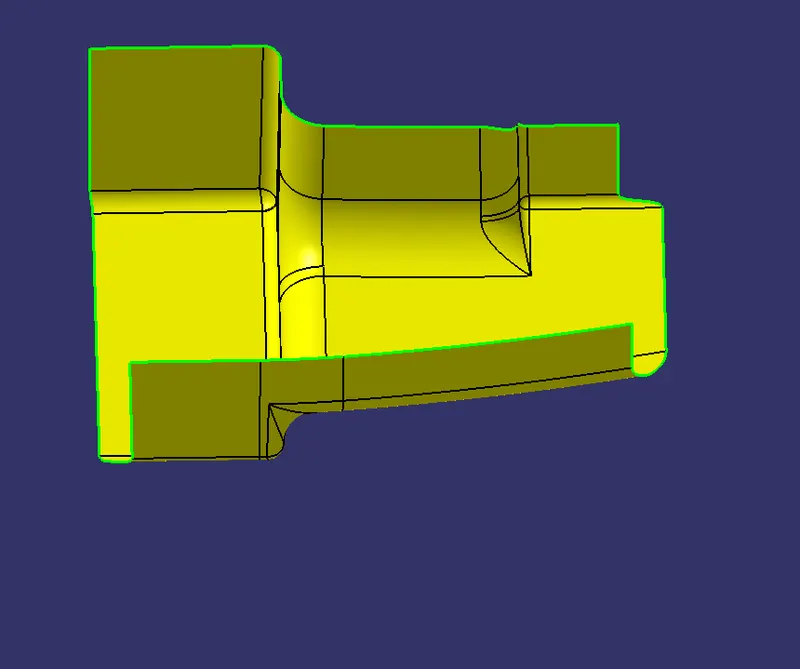
- Offset the given class a surface inside at a thickness of 2.5mm.
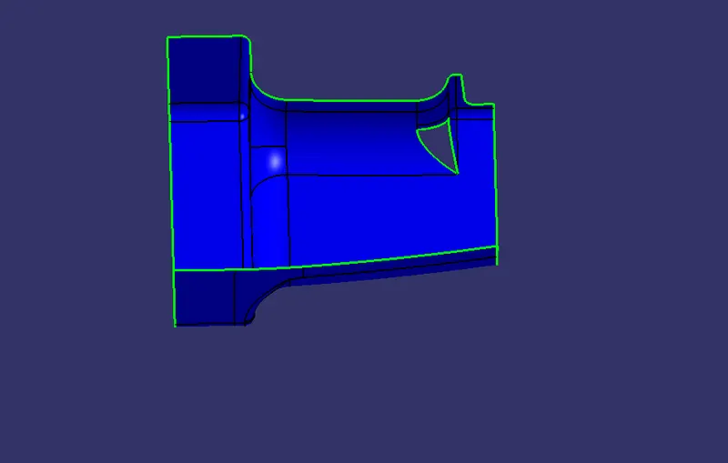
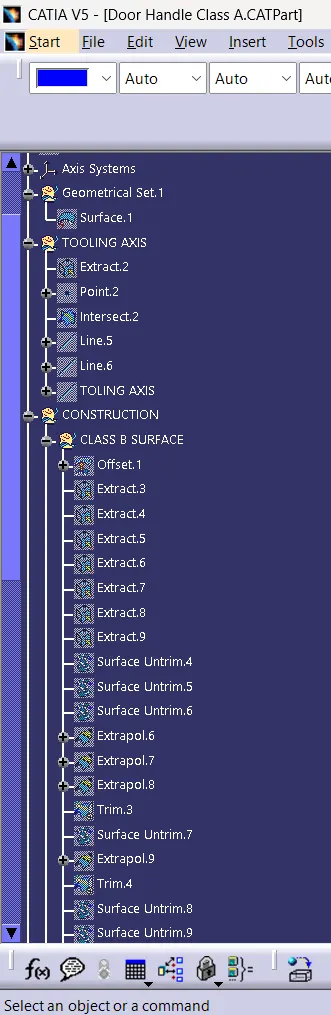
- Some patches are occur while offsetting,using tools like multiple extract,untrim,extrapolate and trim commands clear the patch and create a smooth b surface.
4.CREATION OF C SURFACE
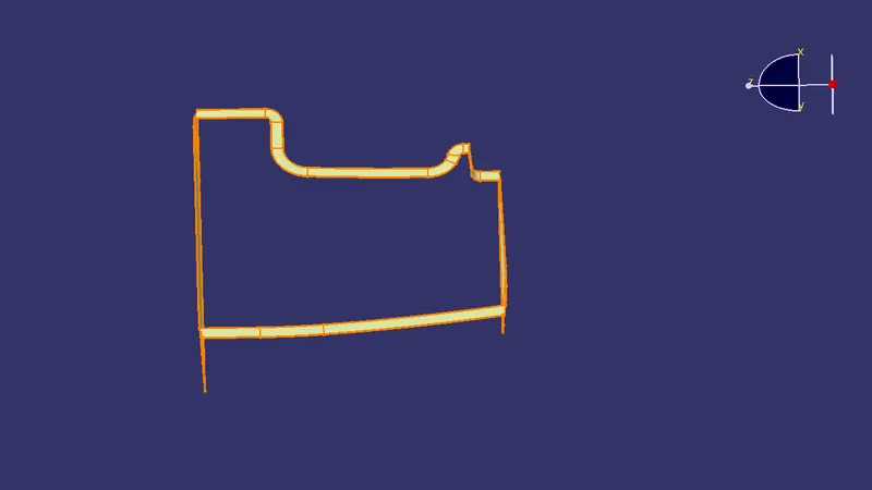
- Extract the boundary from the class A surface using boundary command
- Use sweep command > choose profile type line > subtype as with draft direction > choose guide curve and draft direction > draft angle as 3 degree > preview.
5.CREATION OF SOLID BODY:
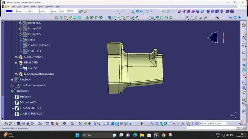
- The solid body is created using close surface feature.
- Boundary is selected and the body is picked. Since an error popped up it can be understood that all surfaces are joined with each other to form a proper closed surface body.
6.RIB CREATION:
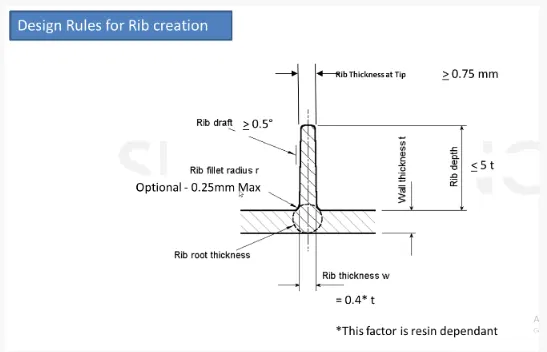
- Design rules for rib
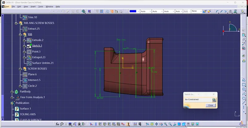
- Sketch for rib creation
- Root thickness analysis
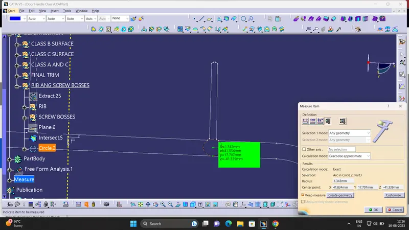
To check the Rib root thickness, first take perpendicular intersection across the body and the Rib and then have to sketch a circle which tangent to the Rib base or root area by using tritangent type circle.
7.SCREW BOSS CREATION:
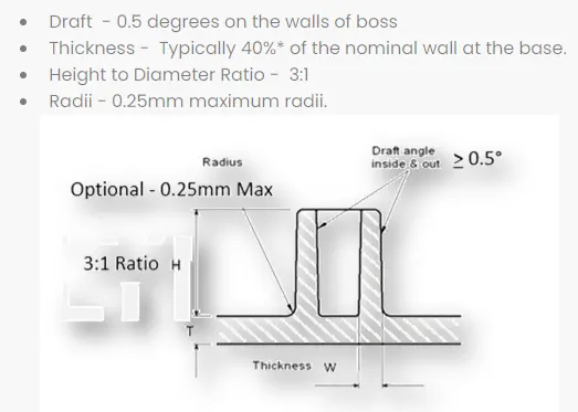
- Design principle for screw boss creation.
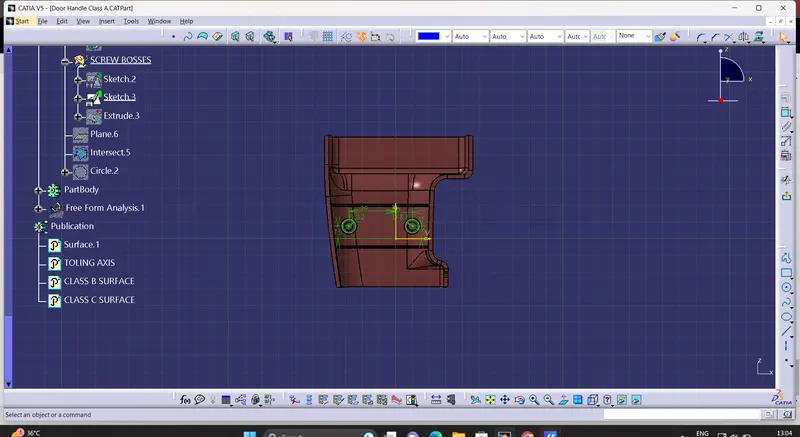
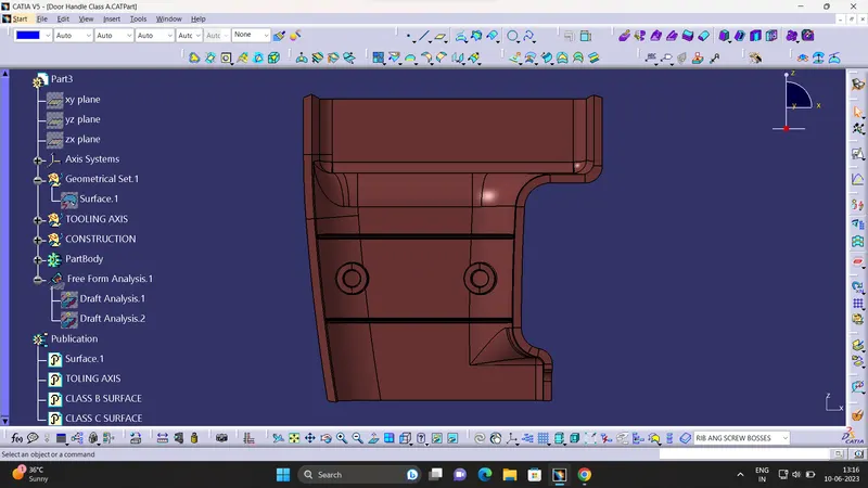
FINAL SOLID BODY:
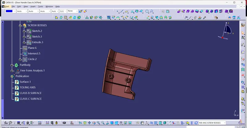
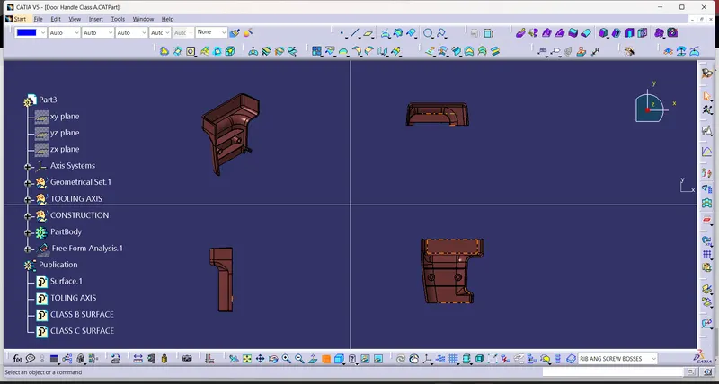
FINAL BODY DRAFT ANALYSIS:
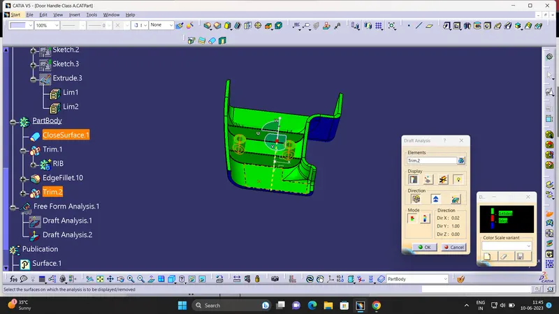
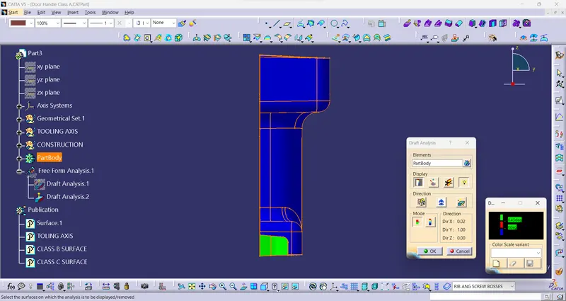
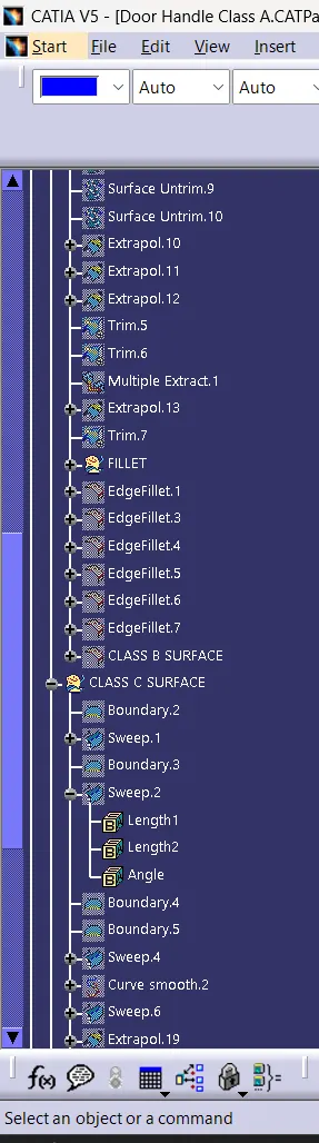
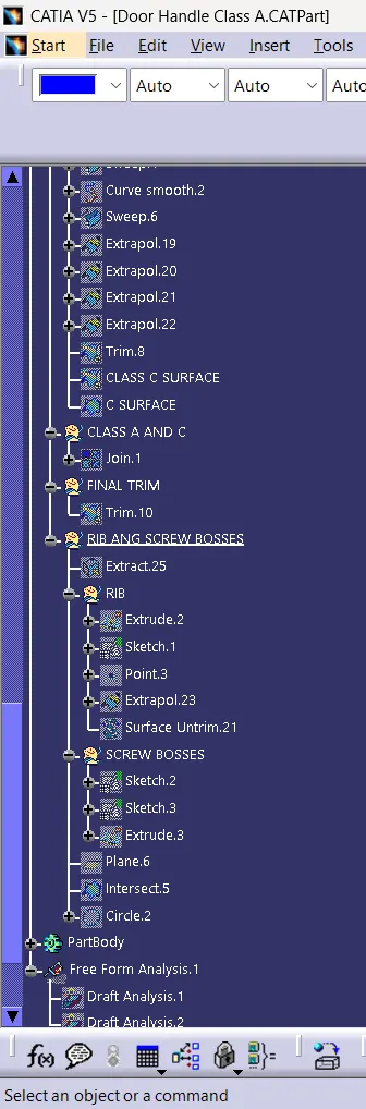
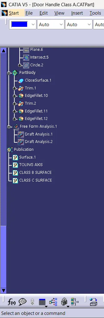
TREE STRUCTURE:
CONCLUSION: Hence the Rib for the drill handle is created considering the design rules for rib creation and Screw boss creation, and Draft analysis is also performed for the final component successfully .