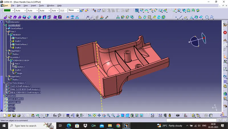
Week 10 - Challenge 1- Attachment Feature Creation (Ribs & Screw Boss)
DOOR HANDLE
AIM : Attachment Feature Creation (Ribs & Screw Boss)
INPUT : CLASS A SURFACE
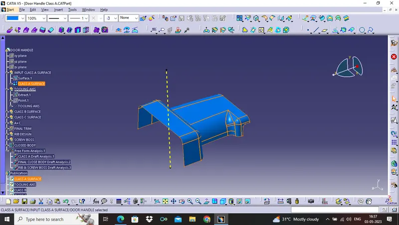
There are following steps, which have to perform by using Class A Surface:-
- First understanding the CLASS A SURFACE.
- Than creating the TOOLING AXIS.
- Draft analysis 1 for CLASS A SURFACE.
- Creating geometrical sets for CLASS B SURFACE.
- Creating CLASS C SURFACE using boundary and sweep command.
- FINAL TRIM to get Final Surface.
- Draft analysis 2 for CLOSE SURFACE BODY.
- RIB DESIGN
- SCREW BOSS DESIGN
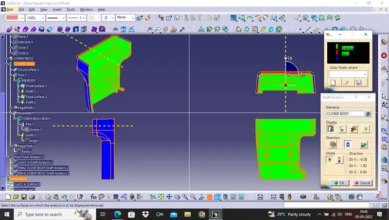
- DRAFT ANALYSIS FOR FINAL CLOSED BODY WITH HAVING ENGINEERING FEATURES RIBS AND SCREW BOSS.
1. First understanding the CLASS A SURFACE.
- Class A Surface is given as an input for product design.
- Class A Surface is thickened by using engineering features.
- The part which is obtaining after Class A Surface get thickened are use for manufacturing in real time application.
- The Boundary Condition of Class A Surface must be checked.
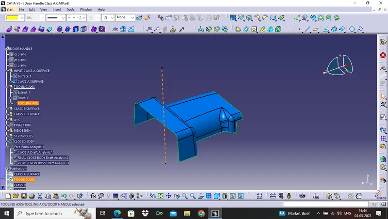
2. CREATING THE TOOLING AXIS
- From Class A Surface, we have to form TOOLING AXIS.
- The point where the component get molded from injection molding.
- On that point, create POINT first using EXTRACT surface.
- On that point, using point direction to form tooling axis.
3. DRAFT ANALYSIS 1 FOR CLASS A SURFACE
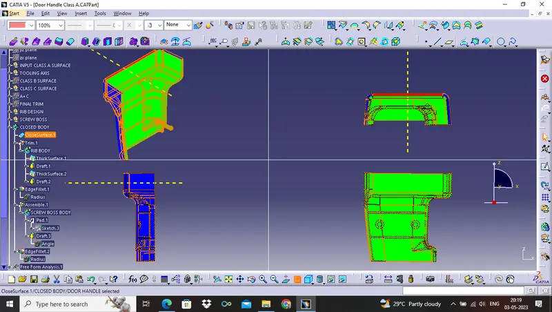
- Draft Analysis technique is used to analyse the product which we design is manufacturable and prevent the part being parallel to the direction of mold opening.
- The product can not be manufacturable, if it has 90° profile, which is parallel to the TOOLING AXIS.
- A small draft angle is applied in order to remove the component from the mold.
- No part is manufacture without the draft angle.
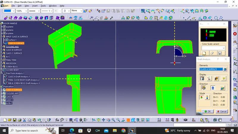
- The green colour represent the draft angle is 0.9°.
- The red colour represent the draft angle is 0°.
- The blue colour represent the draft angle is in negative side.
4. Creating geometrical sets for CLASS B SURFACE
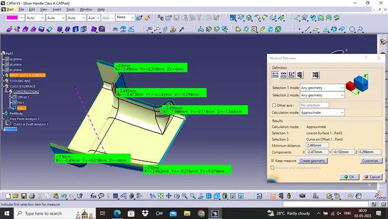
- THICKNESS 2.5 mm is given as input.
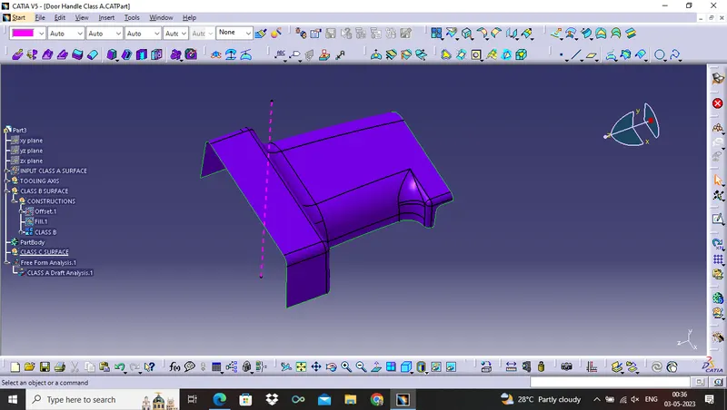
- The CLASS B SURFACE is obtained from CLASS A SURFACE on giving offset with thickness 2.5 mm.
- CLASS B SURFACE is created by using extract CLASS A SURFACES.
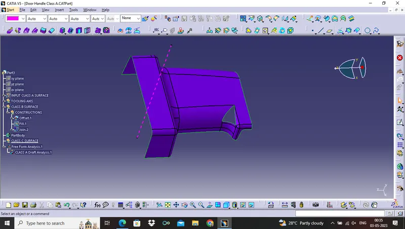
- There is some flaws shown on CLASS B SURFACE , so use require command to get proper CLASS B SURFACE.
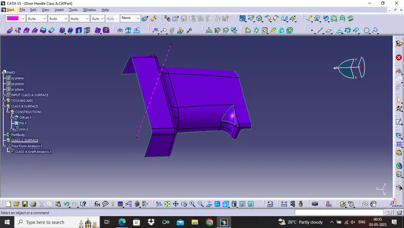
- Using fill command, flaws should be corrected to get CLASS B SURFACE.
FLAWS SHOWN ON CLASS B SURFACE
USING FILL COMMAND
JOIN THE OFFSET AND FILL COMMAND TO GET PROPER CLASS B SURFACE
The offset value 2.5 mm should be ensured from each side or views.
5. CREATING CLASS C COMPONENT
- The CLASS C SURFACE is the final output obtained from the CLASS A and CLASS B Surface.
- Using boundary of CLASS A SURFACE with giving LIMIT and provide boundary and sweep the boundary with draft direction and taking surface as reference too.
- The CLASS C SURFACE has the thickness 2.5 mm and draft value as per requirement provided.
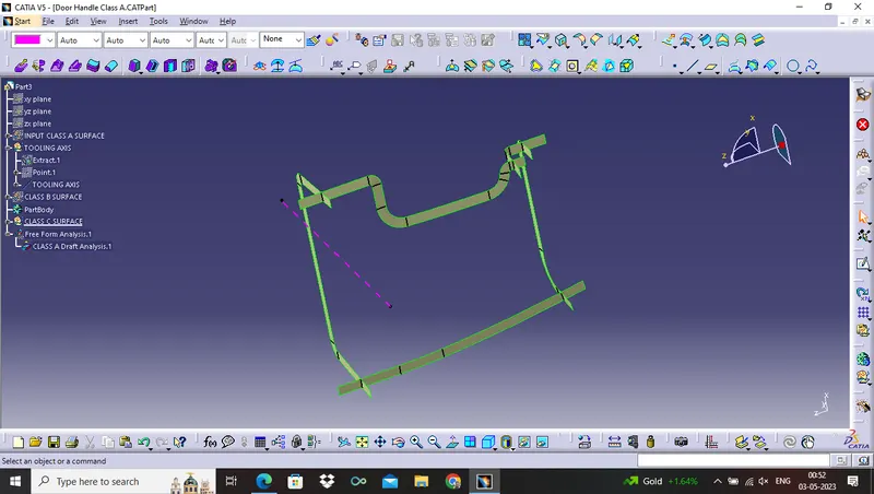
BEFORE FINAL TRIM
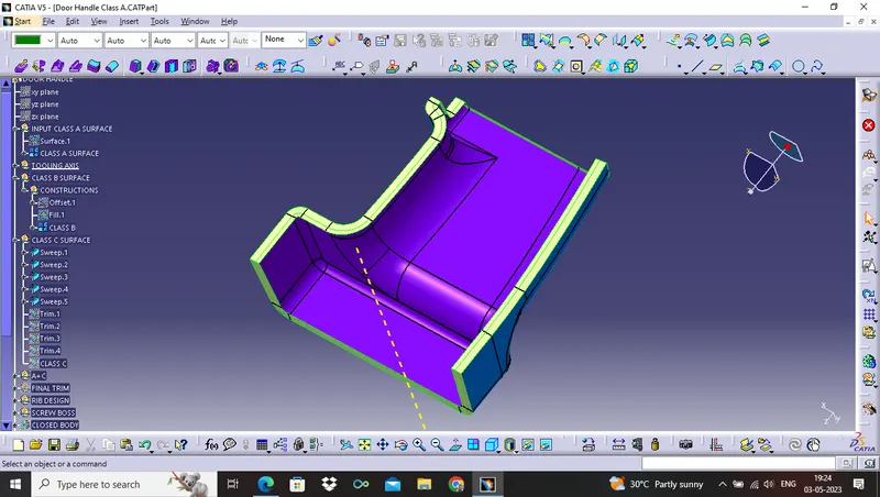
AFTER TRIM TO GET CLASS C SURFACE
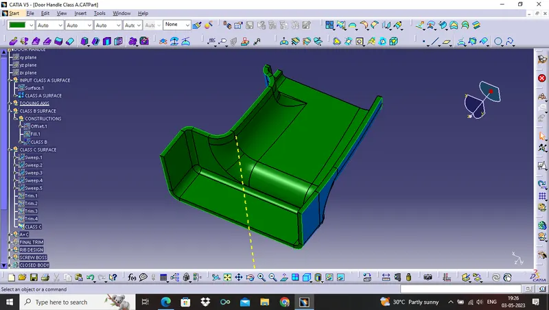
CLASS A + CLASS C = JOIN
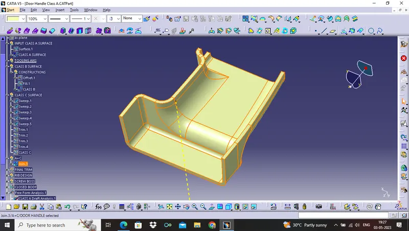
6. AFTER FINAL TRIM SO FINAL DOOR HANDLE SURFACE OBTAINED
- The CLASS A and CLASS C SURFACE are JOIN and TRIM with CLASS B SURFACE to form the final DOOR HANDLE SURFACE.
CLASS A + CLASS B + CLASS C = TRIM 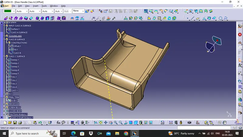
7. DRAFT ANALYSIS FOR CLOSE SURFACE BODY
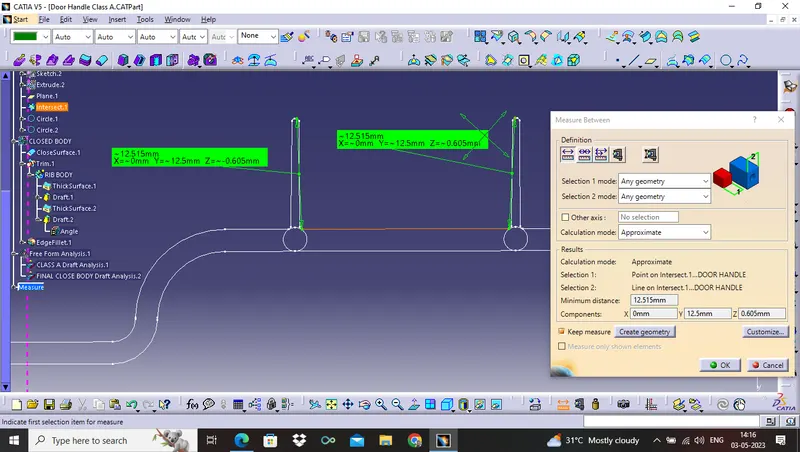
8. RIB DESIGN
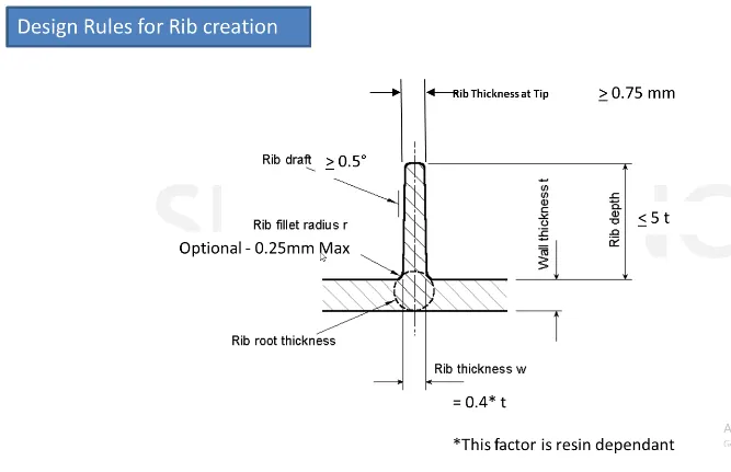
HERE,
WALL THICKNESS = 2.5 MM
DRAFT =0.5 degrees
HEIGHT = 5t = (5*2.5)=12.5 MM
THICKNESS (W) = 0.4*2.5= 1 MM
EDGE FILLET = 0.25 MM
RIB ROOT THICKNESS= 2.686 MM
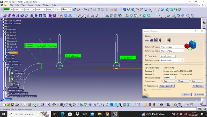
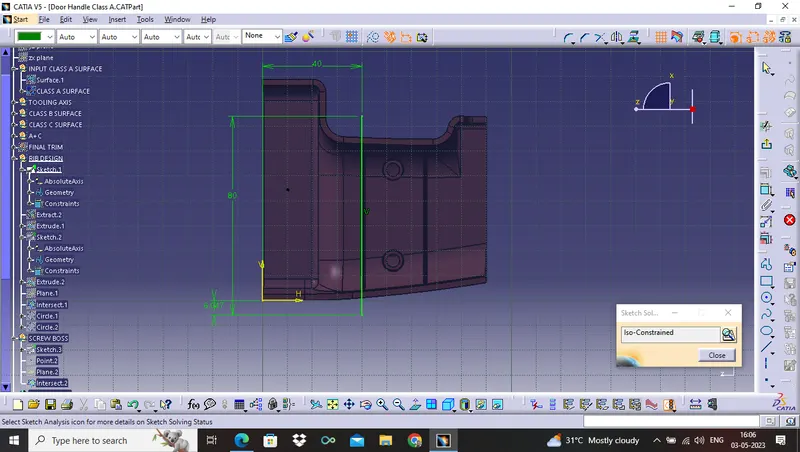
SKETCH 1
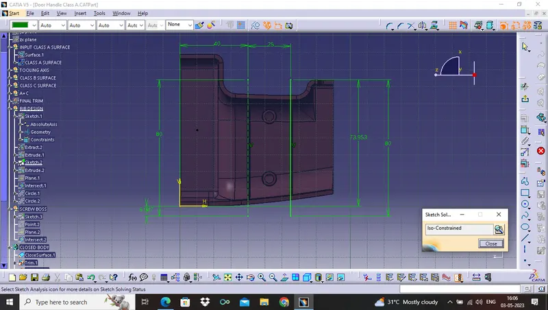
SKETCH 2
9. SCREW BOSS DESIGN
General Guidelines for Bosses:
- Draft - 0.5 degrees on the walls of boss
- Thickness - Typically 40%* of the nominal wall at the base.
- Height to Diameter Ratio - 3:1
- Radii - 0.25mm maximum radii.
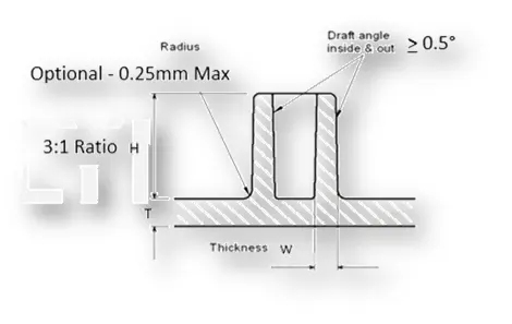
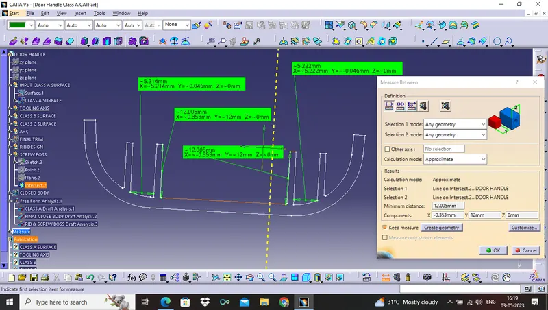
HERE ,
HEIGHT = 12 MM
WHERE, H/B>3
SKETCH 3
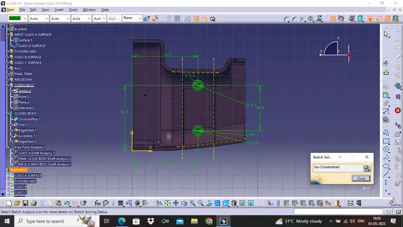
Challenge 1- Attachment Feature Creation (Ribs & Screw Boss)
isometric view + front view + side view + top view
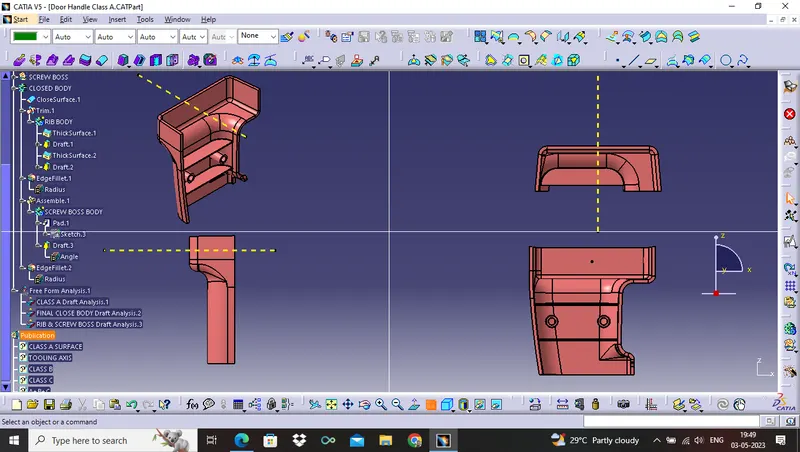
10. DRAFT ANALYSIS FOR FINAL CLOSED BODY HAVING RIBS AND SCREW BOSS AS ENGINEERING FEATURES APPLIED ON CLASS C SURFACE
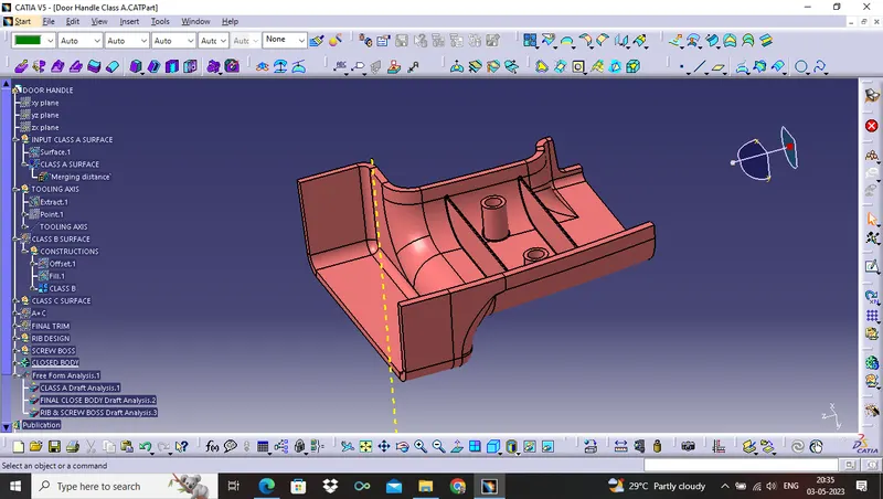
TREE STRUCTURES OF CLASS A , TOOLING AXIS , CLASS B
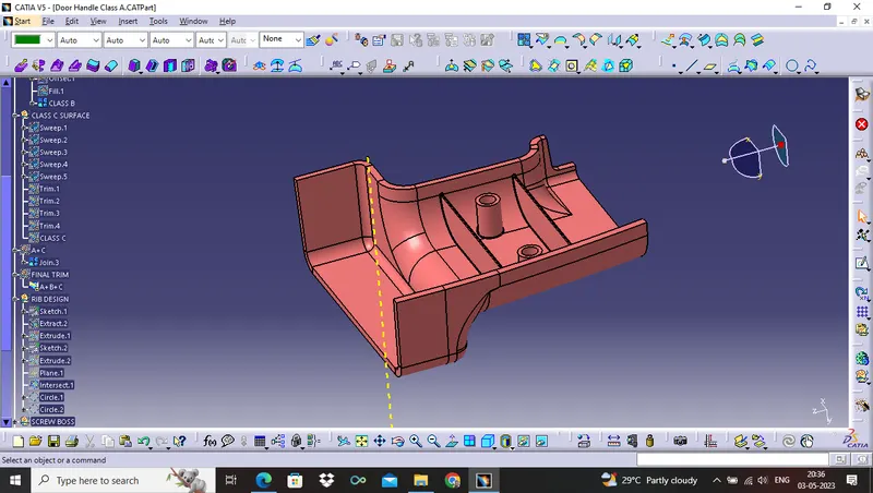
TREE STRUCTURES OF CLASS C
TREE STRUCTURES OF RIBS AND SCREW BOSS
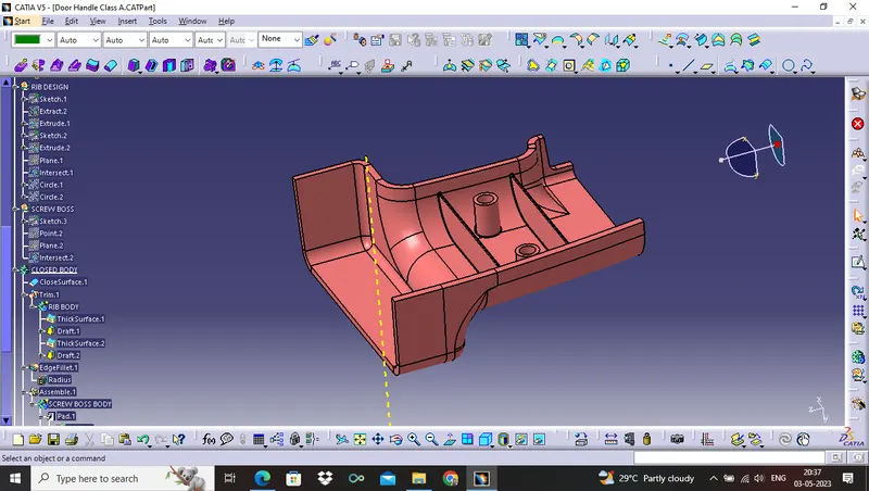
TREE STRUCTURES OF CLOSED BODY , DRAFT ANALYSIS AND PUBLICATION