Week 9 - Challenge 2 - Switch Bezel Design
SWITCH BEZEL
AIM:
To create SWITCH BEZEL Plastic Component from the given CLASS A surface as an input.
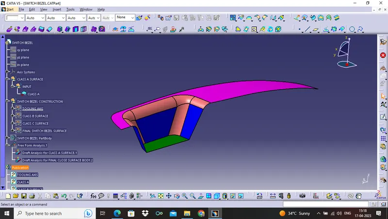
There are following steps, which have to perform by using Class A Surface :-
- First understanding the CLASS A SURFACE.
- Create Axis System.
- Than creating the TOOLING AXIS.
- Draft analysis for CLASS A SURFACE.
- Creating geometrical sets for CLASS B SURFACE.
- Creating CLASS C SURFACE using boundary and sweep command.
- FINAL TRIM to get Final Surface.
- Than go to PART DESIGN to get Close Surface Body.
- Draft analysis for CLOSE SURFACE BODY.
1. First understanding the CLASS A SURFACE.
- Class A Surface is given as an input for product design.
- Class A Surface is thickened by using engineering features.
- The part which is obtaining after Class A Surface get thickened are use for manufacturing in real time application.
- The Boundary Condition of Class A Surface must be checked.
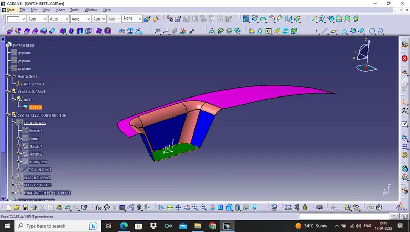
2. CREATING THE AXIS SYSTEM
- First EXTRACT the BASE of CLASS A surface.
- Create point on that Extract surface and create Axis System
3. CREATING THE TOOLING AXIS
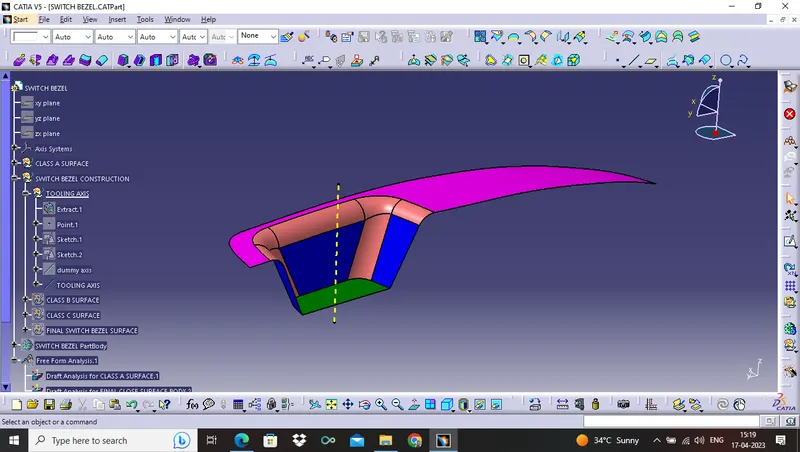
- From Class A Surface, we have to form TOOLING AXIS.
- The point where the component get molded from injection molding.
- The point which is on Axis System, create line on that point normal to the surface, which is Base of CLASS A surface.
- So tooling axis obtained from that point.
4. DRAFT ANALYSIS FOR CLASS A SURFACE
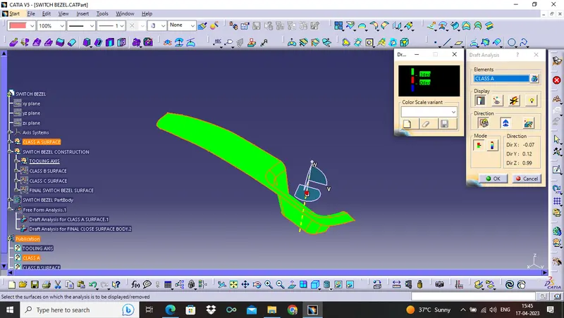
- Draft Analysis technique is used to analyse the product which we design is manufacturable and prevent the part being parallel to the direction of mold opening.
- The product can not be manufacturable, if it has 90° profile, which is parallel to the TOOLING AXIS.
- A small draft angle is applied in order to remove the component from the mold.
- No part is manufacture without the draft angle.
DRAFT ANALYSIS FOR CLASS A SURFACE
ISOMETRIC VIEW
FRONT VIEW
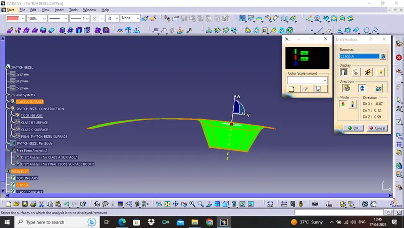
SIDE VIEW
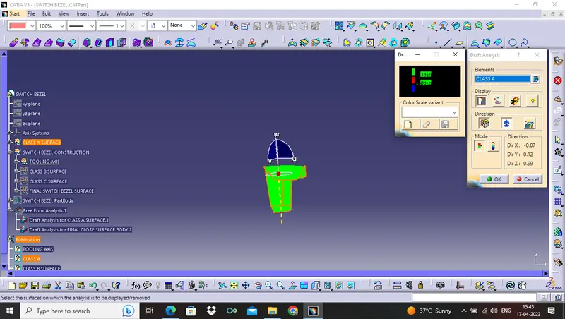
TOP VIEW
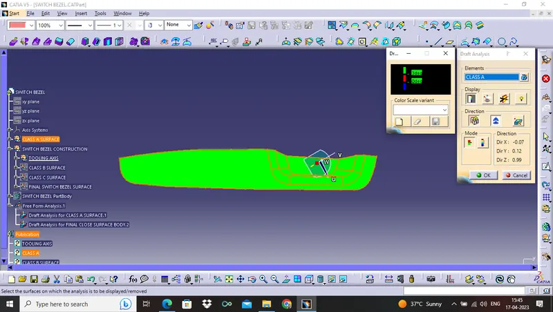
- The green colour represent the draft angle is above 3°.
- The red colour represent the draft angle is 0°.
- The blue colour represent the draft angle is in negative side.
5. Creating geometrical sets for CLASS B SURFACE
- THICKNESS 2.5 mm is given as input.
- The CLASS B SURFACE is obtained from CLASS A SURFACE on giving offset with thickness 2.5 mm.
- CLASS B SURFACE is created by using extract CLASS A SURFACES one by one (TOP SURFACE, SIDE WALLS, BASE SURFACE), than untrim all extract surfaces, than extrapolate each of untrim surfaces, than trim all surfaces and get offset of that trim surfaces with thickness 2.5 mm.
- The offset value 2.5 mm should be ensured from each side or views.
THE OFFSET VALUE FOR FILLET SIZE :-
- THICKNESS + RADIUS = OFFSET INSIDE THE CLASS A
- THICKNESS - RADIUS = OFFSET OUTSIDE THE CLASS A
Here, the EDGE FILLET 1 RADIUS value for given SWITCH BEZEL is 15 mm.
and THICKNESS = 2.5 MM
SO, The offset is OUTSIDE the CLASS A SURFACE = 15 - 2.5=12.5 mm
Edge Fillet 1 size of CLASS B SURFACE is 12.5 mm
AND, the EDGE FILLET 2 RADIUS value for given SWITCH BEZEL is 14 mm.
SO, The offset is OUTSIDE the CLASS A SURFACE = 14 - 2.5=11.5 mm
Edge Fillet 2 size of CLASS B SURFACE is 11.5 mm
6. CREATING CLASS C COMPONENT
- The CLASS C SURFACE is the final output obtained from the CLASS A and CLASS B Surface.
- Using boundary of CLASS A SURFACE with giving LIMIT and provide smooth boundary and sweep the boundary with draft direction is tooling axis with value of draft angle 3°.
- The CLASS C SURFACE has the thickness 2.5 mm and draft value as per requirement provided.
CLASS A + CLASS B + CLASS C = FINAL SURFACE WITHOUT TRIM
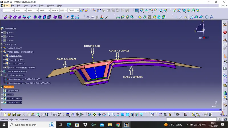
7. AFTER FINAL TRIM SO FINAL SWITCH BEZEL SURFACE OBTAINED
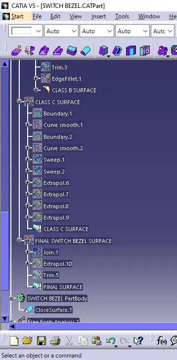
- The CLASS A and CLASS C SURFACE are JOIN and TRIM with CLASS B SURFACE to form the final SWITCH BEZEL SURFACE.
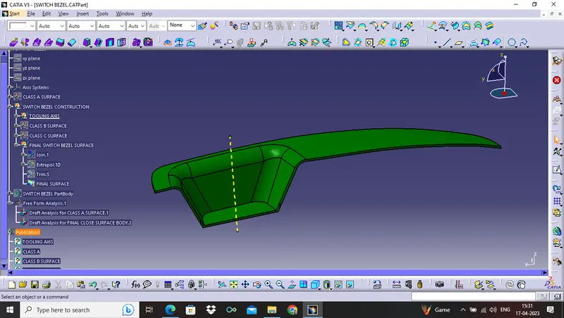
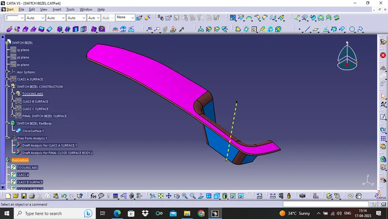
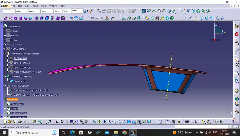
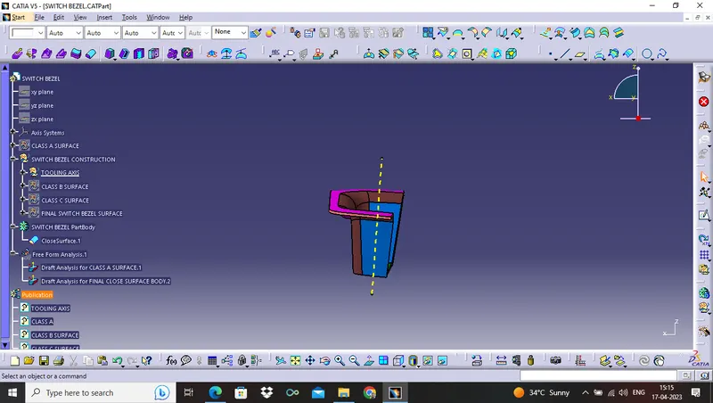
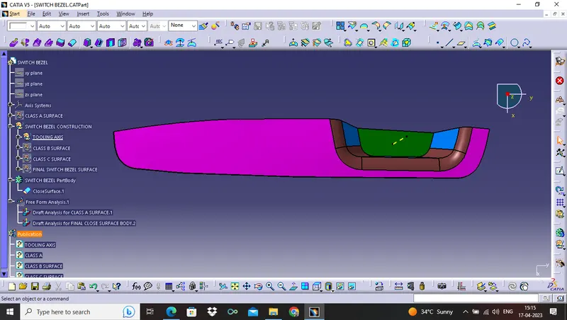
8. GO TO PART DESIGN TO GET CLOSE SURFACE BODY
ISOMETRIC VIEW
FRONT VIEW
SIDE VIEW
TOP VIEW
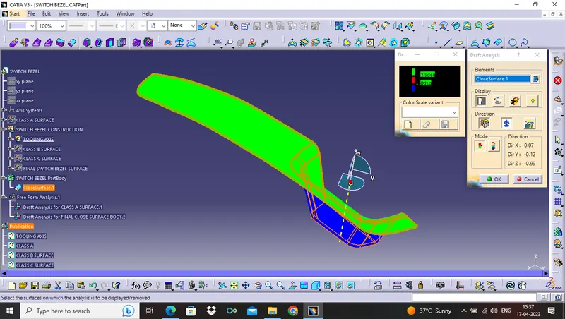
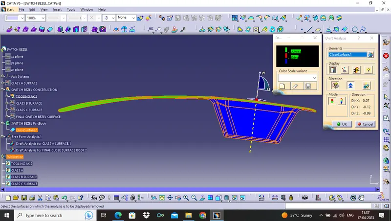
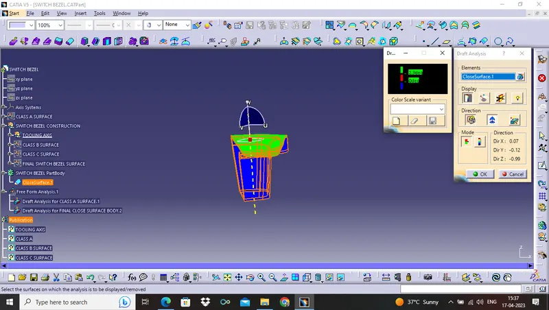
9. DRAFT ANALYSIS FOR SWITCH BEZEL FINAL CLOSE BODY
ISOMETRIC VIEW
FRONT VIEW
SIDE VIEW
TOP VIEW
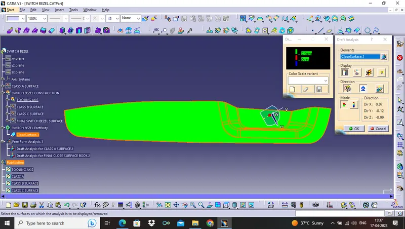
- The green colour represent the draft angle is above 3°.
- The red colour represent the draft angle is 0°.
- The blue colour represent the draft angle is in negative side.
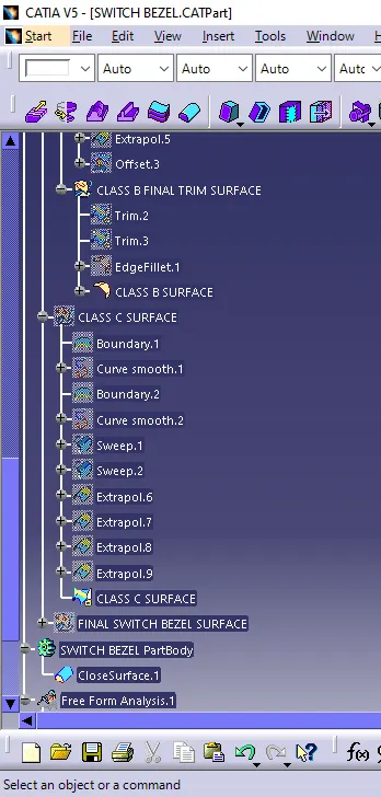
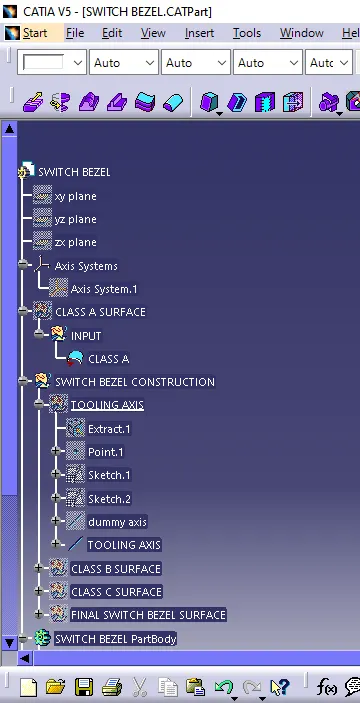
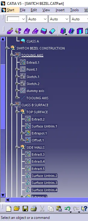
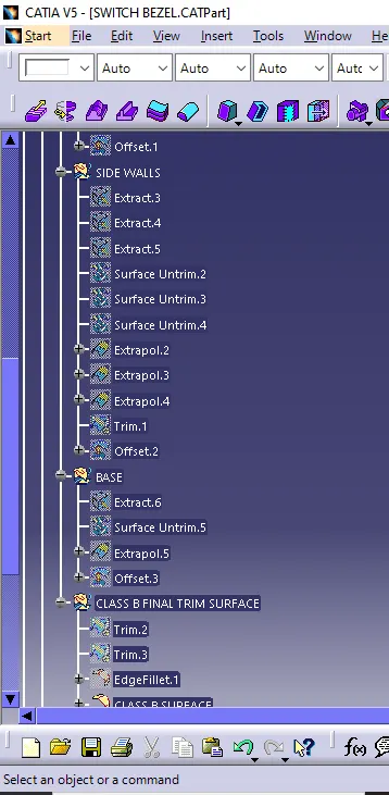
TREE STRUCTURE(CLASS A , TOOLING AXIS, CLASS B)
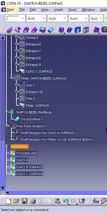
TREE STRUCTURE ( CLASS C, CLOSE BODY, DRAFT ANALYSIS, AND PUBLICATION )