Week 10 Bullet penetrating a Bucket Challenge
OBJECTIVE:
To simulate bullet penetrating a bucket for different cases of bucket material.
CASE 1: Aluminum Alloy NL.
CASE 2: Structural Steel NL.
CASE 3: Stainless Steel NL.
1. THEORY
1.1 Bullet Penetration:
A bullet is a projectile, often a pointed metal cylinder, that is shot from a firearm. The bullet is usually part of an ammunition cartridge, the object that contains the bullet and that is inserted into the firearm.
Bullets are made of a variety of materials. Lead or a lead alloy is the traditional bullet core material. Traditional bullet jackets are made of copper or gilding metal, an alloy of copper and zinc. Many other materials are used in bullets today, including aluminium, bismuth, bronze, copper, plastics, rubber, steel, tin, and tungsten.
Modern bullets can have many different features. Some of these features concern the shape of the bullet and others the materials of construction. Most bullets look like a cylinder with a pointed end. The cylindrical section to the rear of the bullet is the shank and the pointed section to the front of the bullet is the tip, though the tip may be flat instead of pointed. Bullets can be made of one or more materials.
Bullets made out of only soft material (such as lead) expand on impact causing more damage to the target. Bullets made out of only a harder material (such as steel) penetrate further into thicker targets but do not expand much. A softer core can be enclosed or partially enclosed in a layer of harder metal called a jacket. This jacket can completely enclose the bullet or it can leave the softer tip exposed for expansion purposes. Varying the amount of jacketing alters the amount of penetration versus expansion.
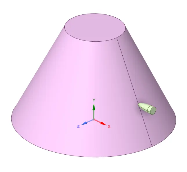
In this project, a truncated cone-shaped bucket made of materials like aluminium alloy NL, copper alloy NL and stainless steel NL, is hit with a bullet travelling at a speed of 139000 mm/s. The results are drawn to study the impact of the bullet on the bucket, as well as the behaviour exhibited by the material of the bucket.
2. STEPS FOR PERFORMING ANALYSIS:
1. Open ANSYS workbench.
2. Select the static structural module.
3. Select the proper Engineering data card.
4. Import geometry.
5. Open Mechanical model.
6. Give proper connections (contacts and joints).
7. Generate mesh.
8. Set Analysis Setting as given.
9. Insert output request
10. Analyze Result.
3. ANALYSIS SETUP:
3.1 Geometry:
3.2 Meshed Model:
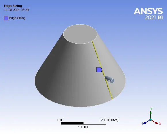
Fig. 3.2(a) Edge Sizing
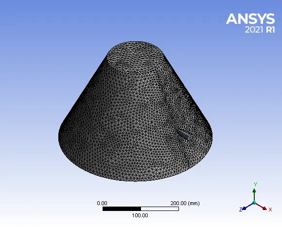
Fig. 3.2(b) Meshed Model
- Details:
- Edge Sizing = 60 Divison
- Mesh Size = 8 mm
- No of Nodes = 8640
- No of Elements = 24903
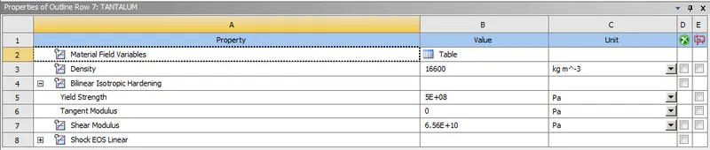
3.3 Material Properties:
For Bullet:
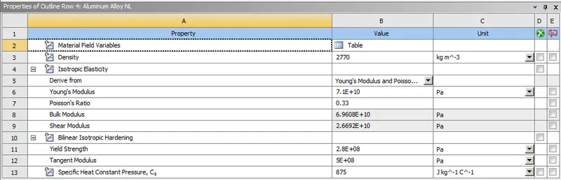
(A) CASE 1: Aluminium Alloy NL
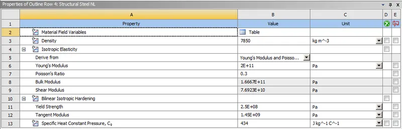
(B) CASE 2: Structural Steel NL
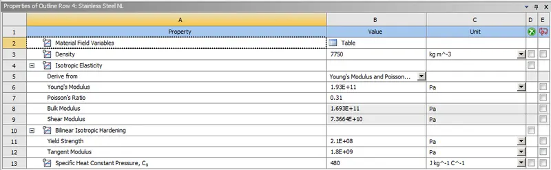
(C) CASE 3: Stainless Steel NL
3.4 BOUNDARY CONDITIONS:
3.4.1 Analysis Setting:
Now let's define the Analysis Setting.
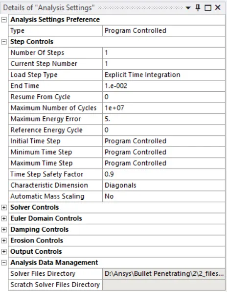
In the analysis settings, the number of steps considered is 1. The end time specified is 1e-002. The maximum no. of cycles is 1e+07. The maximum energy error is 5. The initial, minimum and maximum time step is set to ‘Program Controlled’.
3.4.2 Other Boundary Conditions:
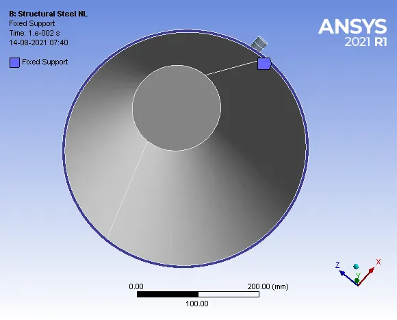
1. Fixed Support: The bottom surface of the bucket is fixed.
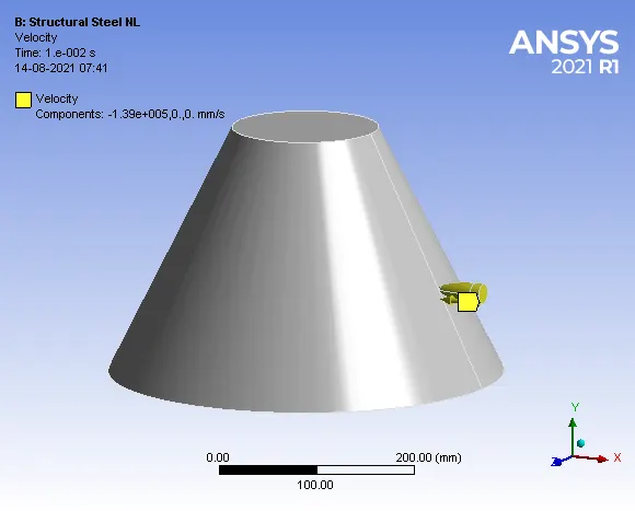
2. Velocity: Velocity applied to bullet along negative x-axis. The bullet is directed to hit the bucket with a velocity of 139000 mm/s.
3.5 SOLUTION:
- After giving proper Boundary conditions, create a solution for the output result.
- Total Deformation pf Model.
- Equivalent Stress of Model.
4. RESULT AND DISCUSSIONS:
(A) CASE 1: Aluminum Alloy NL.
1. Total Deformation:
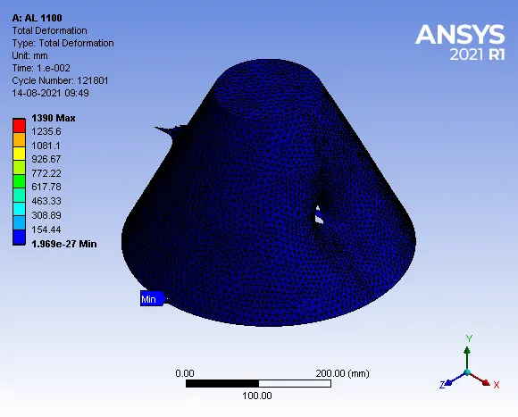
Maximum Deformation = 1390 mm
- Deformation Contours:
2. Equivalent v-m Stress:
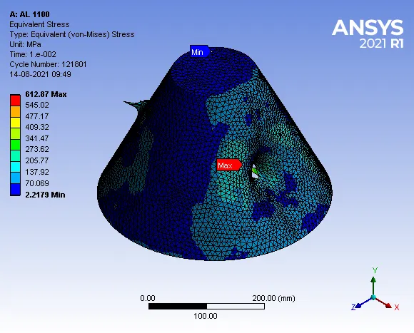
Maximum Stress = 612.87 MPa
- Stress Contours:
3. Energy Plots:
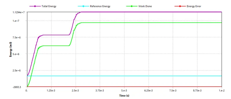
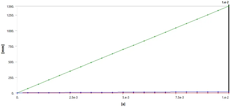
From the energy conservation plot, it is observed that the work done graph indicated by the green line shows an initial spike which indicates that the bullet has impacted the bucket and later the graph is steady meaning the bullet has penetrated through the bucket and is travelling with constant velocity and later there is again spike in the graph which indicates that the bullet has impacted the other side of the bucket and thereafter the graph is constant which indicates that the bullet has been pushed out of the bucket and is travelling at a constant velocity. The energy error indicated by the red line shows that there is negligible energy error.
(B) CASE 2: Structural Steel NL
1. Total Deformation:
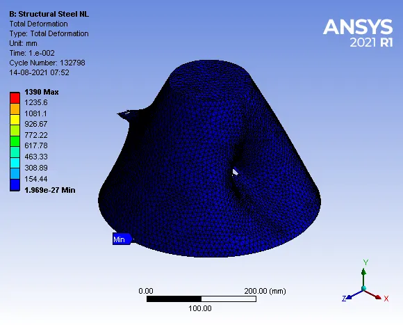
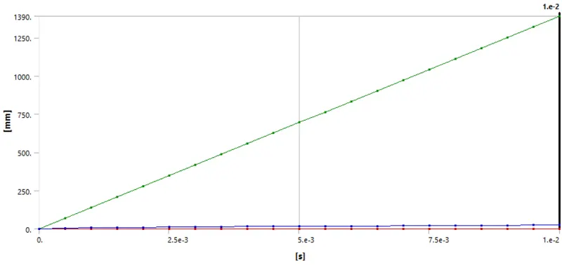
Maximum Deformation= 1390 mm
- Deformation Contours:
2. Equivalent v-m Stress:
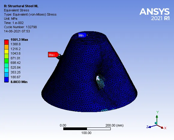
Maximum Stress = 1561.3 MPa
- Stress Contours:
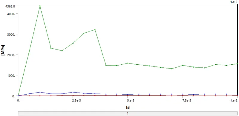
3. Energy Plots:
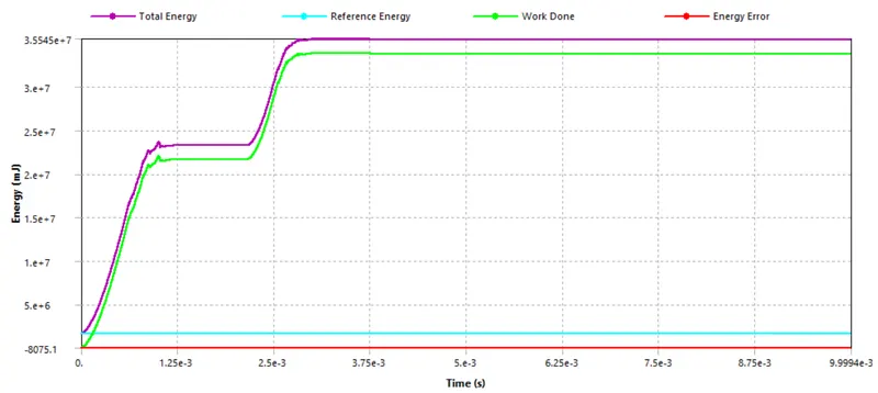
From the energy conservation plot, it is observed that the work done graph indicated by the green line shows an initial spike which indicates that the bullet has impacted the bucket and later the graph is steady meaning the bullet has penetrated through the bucket and is travelling with constant velocity and later there is again spike in the graph which indicates that the bullet has impacted the other side of the bucket and thereafter the graph is constant which indicates that the bullet has been pushed out of the bucket and is travelling at a constant velocity. The energy error indicated by the red line shows that there is negligible energy error.
(C) CASE 3: Stainless Steel NL
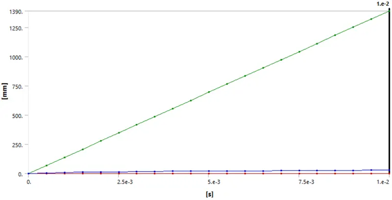
1. Total Deformation:
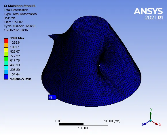
Maximum Deformation = 1390 mm
- Deformation Contours:
2. Equivalent v-m Stress:
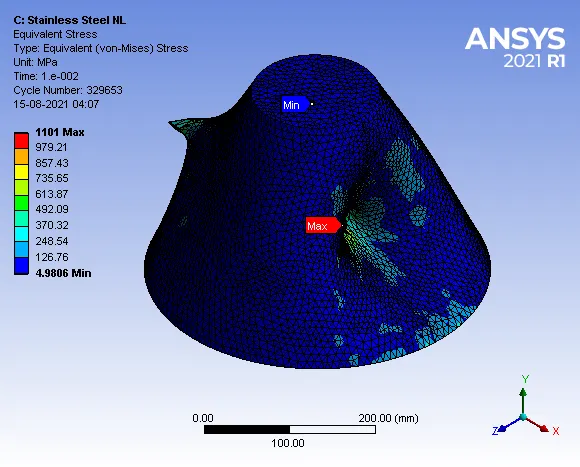
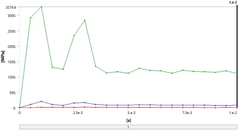
Maximum Stress = 1101 MPa
- Stress Contours:
3. Energy Plots:
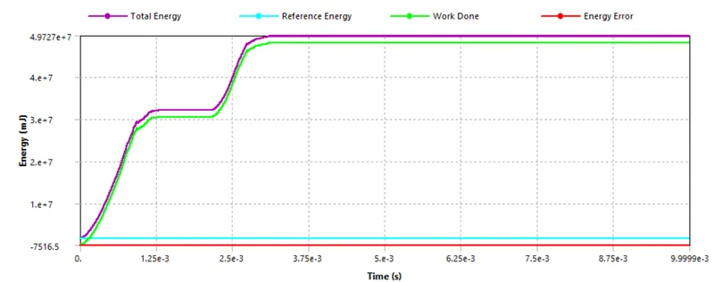
From the energy conservation plot, it is observed that the work done graph indicated by the green line shows an initial spike which indicates that the bullet has impacted the bucket and later the graph is steady meaning the bullet has penetrated through the bucket and is travelling with constant velocity and later there is again spike in the graph which indicates that the bullet has impacted the other side of the bucket and thereafter the graph is constant which indicates that the bullet has been pushed out of the bucket and is travelling at a constant velocity. The energy error indicated by the red line shows that there is negligible energy error.
5. Comparison of Results:
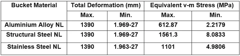
The v-m stress developed for case-2 is maximum compared to other cases because the value of yield strength and Poisson’s ratio of stainless-steel NL is less compared to other cases.
6. CONCLUSION:
1. Simulation of a bullet penetrating a bucket was carried out successfully for the following cases of bucket material.
- Case-1: Aluminium Alloy NL.
- Case-2: Structural Steel NL.
- Case-3: Stainless Steel NL.
3. The v-m stress developed for case-2 is maximum compared to other cases because the value of yield strength and Poisson’s ratio of structural-steel NL is less compared to other cases.
4. Generally, the effect of penetration of the bullet into a metallic object depends upon the thickness and density of the material.