Week 10 - Axial Compressor
Objective:
Find out the average mass flow rate at the outlet of a single-stage compressor which comprises 16 rotor blades and 32 stator blades
- Assume the rotational speed of 37500 rpm
- Choose an appropriate time step for the simulation
- Plot contour for
- static pressure
- static temperature
- Determine regions where high-temperature conditions prevail.
Answer:
The project is about the simulation of single stage compressor to determine the average mass flow rate at the outlet.
Input:
Rotor speed: 37500 rpm
Rotor blades: 16
Stator blades: 32
Following model with mesh has been received as input:
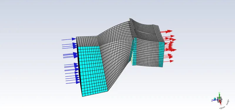
Creating Periodic Zones
Console commands has been used to create the periodic boundary conditions for the zones which are in between rotor & stator and also at the end of stator to define their periodic nature.
The rotor has 16 blades and we are using one zone between one set of blades to simulate the air movement condition. The objective to set these zones as periodic is to indicate the software that these zones are common in other 15 locations.
Commands used to assign Periodic BC
- First by pressing enter into console initlal options pop-up in the console.
- We meed to change the boundary condition of mesh thats why selecting mesh by entering into commnad line.
- Next step is selecting "modify zones" because it contains the list of zones from which we need to chnage boundary conditions of some zones.
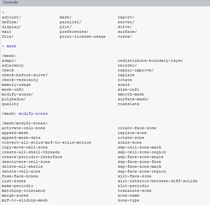
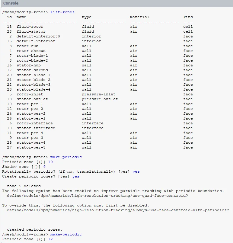
- To know the ID number of each zone, "list zones" command is used.
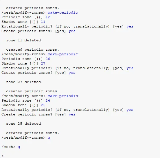
- To assign periodic boundary conditions, the respective faces have been first identified. Following pairs have been assigned periodic boundary conditions.
10 - 9
12 - 11
26 - 27
24 - 25
After assigning periodic bc, the shadow zone has been deleted by software for every periodic bc.
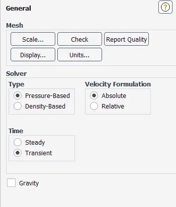
Solver & Transient condition settings:
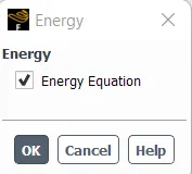
Turning on Energy equation
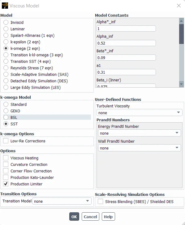
Viscous Model:
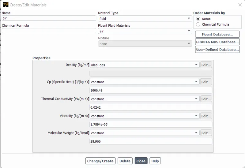
Material:
Cell Zone Conditions:
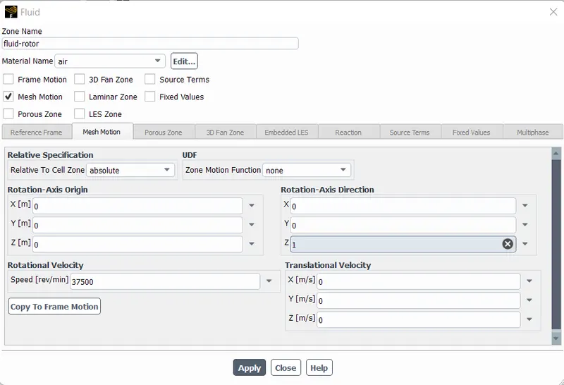
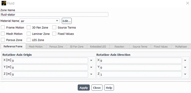
Rotor cell zone has been set for Moving Mesh approach while the stator has been kept as default because stator doesnot rotate.
Rotor Cell Zone Conditions:
37500 RPM is inserted as rotor's angular velocity.
Stator Cell Zone Conditions:
Boundary Conditions:
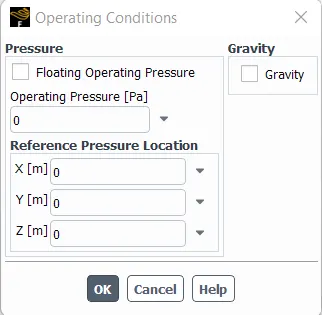
Changing operating conditions because inlet condition is based on the operating condition as well.
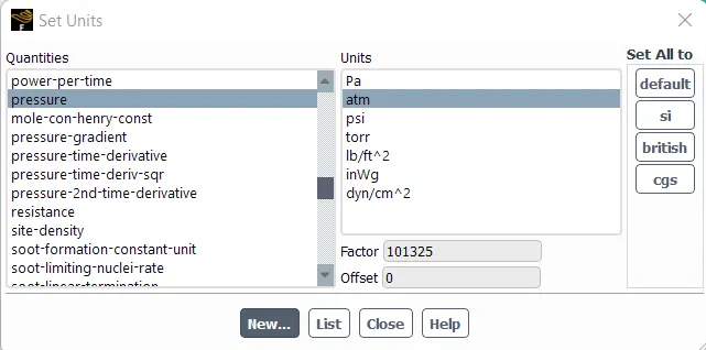
Changing Pressure Unit:
Inlet BC:
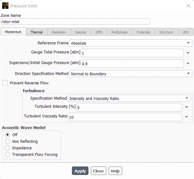
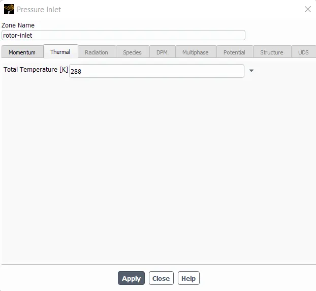
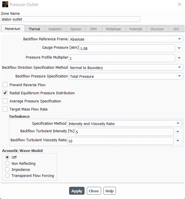
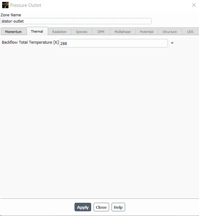
Outlet BC:
The "Radial Equilibrium Pressure Distribution" option is turned on to apply the gauge pressure radially.
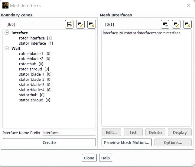
Creating Mesh Interface
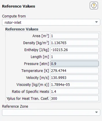
Reference Values
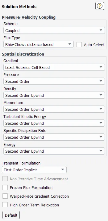
Solution Methods
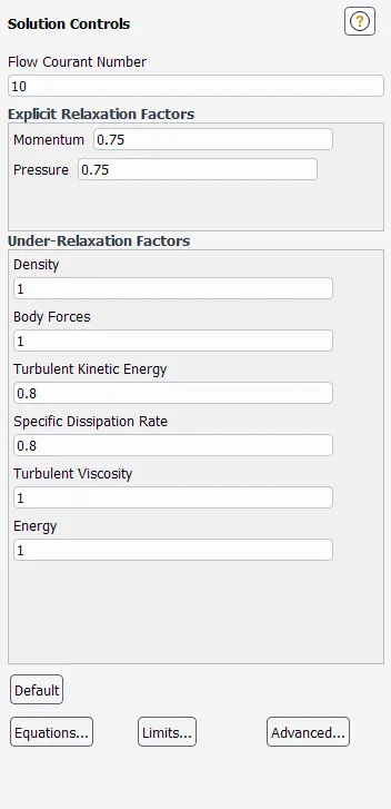
Setting Courant Number
Report Definitions:
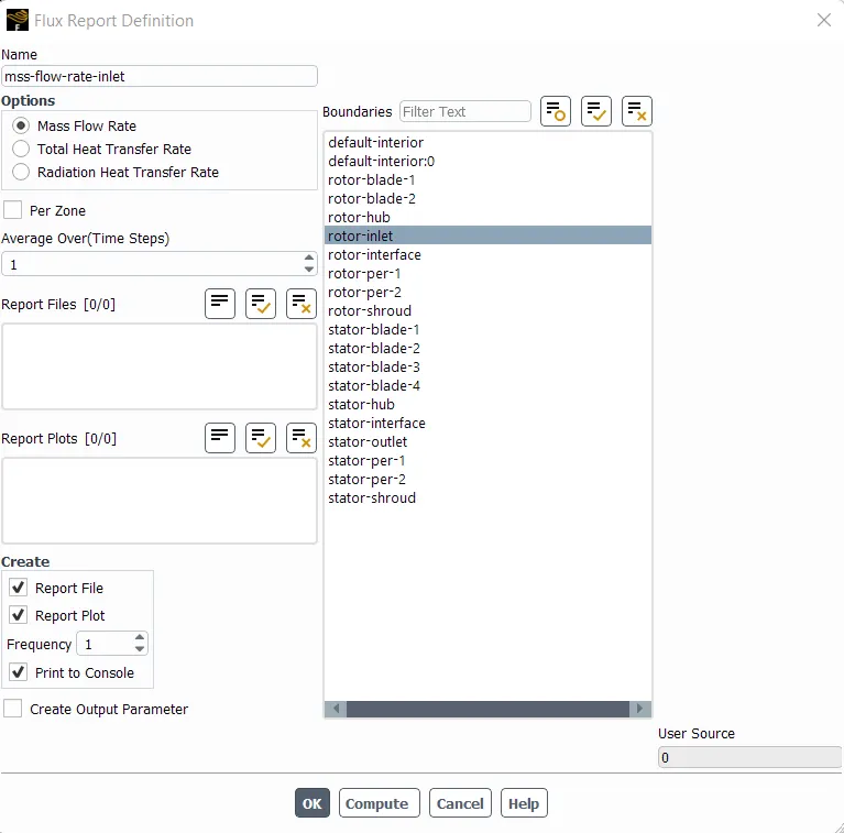
Mass Flow Rate - Inlet
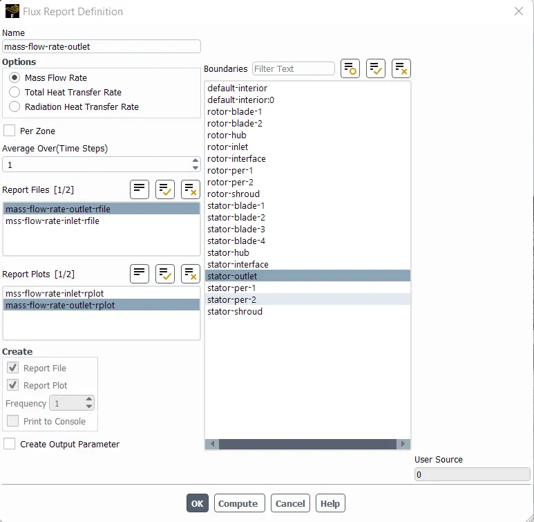
Mass Flow Rate - Outlet
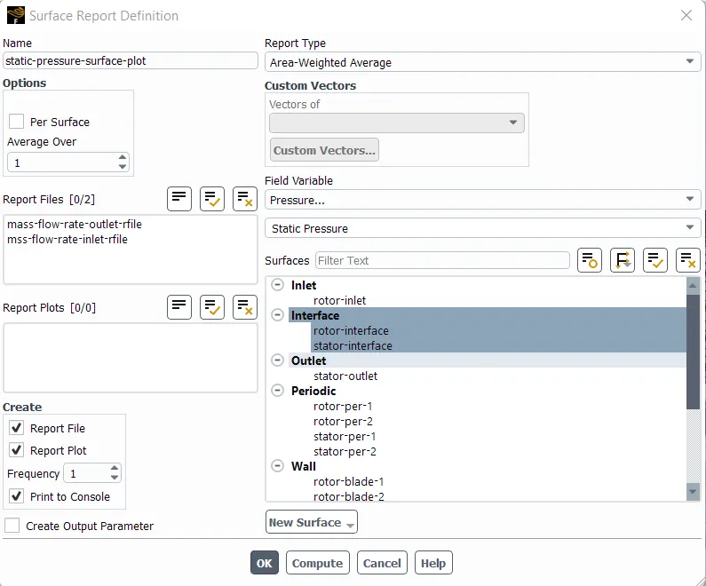
Static Pressure - Area Weighted Average Surface Plot
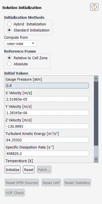
Initialization
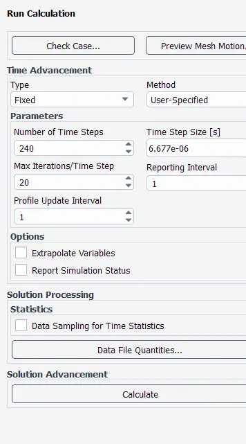
Calculating time step size:
- Setting time step size in a way that one pass of the rotor divides into 15 time steps.
- Rotor has 16 blades.
- So, in each time step Rotor rotates = 360/16/15 = 1.5 degree
- Rotational speed of Rotor = 37500 rpm
Converting into deg/sec = 225000 deg/sec
- So, Time step size = 1.5/225000 = 6.677e-06 sec
- To get one (1) complete rotation,
Required Number of Time Steps = 16 * 15 = 240 time steps
Maximum number of iterations per time step has been kept at 20.
Results:
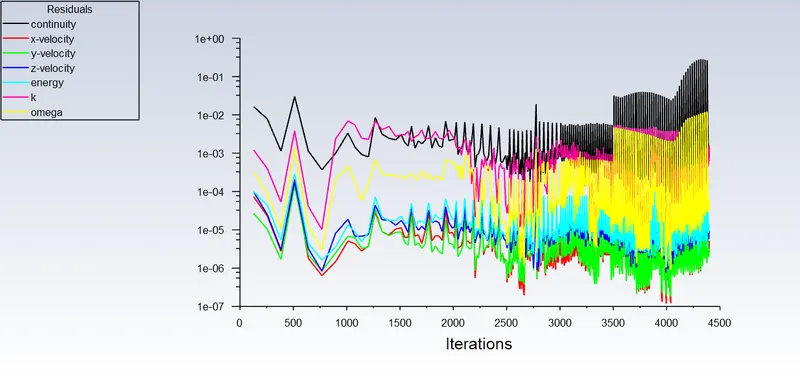
Residual Plot
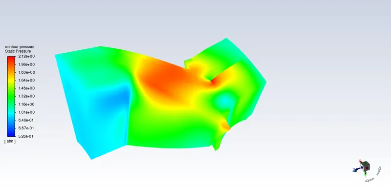
Static Pressure
Static Temperature
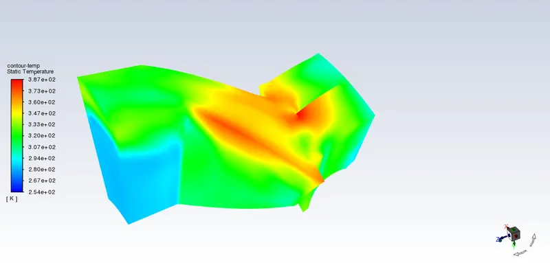
As we can see from the above image that the maximum temperature is generated where the red & orange color is developed which is the top portion of rotor blades & top portion of central stator blade. The initial region of stator blades have also experienced the nearer to the maximum temperature. The maximum temperature is 387 degrees which can seen in temperature contour colormap bar.
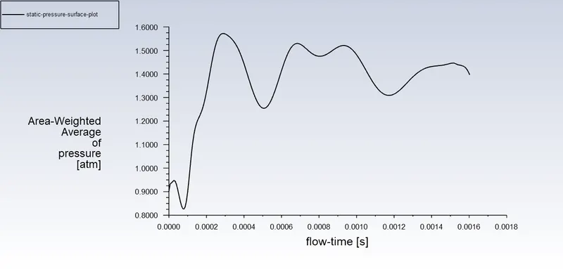
Area Weighted Average Plot of Static Pressure
The area weighted average pressure is the static pressure at the interface of the rotor & the stator.

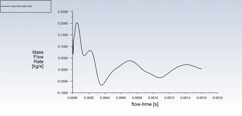
Mass Flow Rate - Inlet

Mass Flow Rate - Outlet
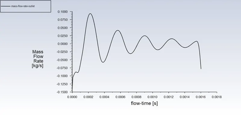
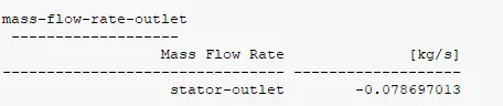
The mass flow rate in the outlet plot is negative because the mass is flowing out of the system.