Week 10- Assembly Workbench
AIM:To use of given dimensions create a sketches and change a sketches into solid through part design than assemble all parts in assembly design.
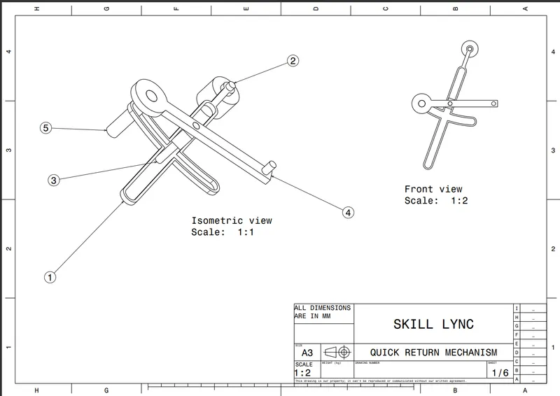
QUICK RETURN MECHANISM:
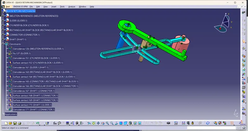
A quick return mechanism is an apparatus to produce a reciprocating motion in which the time taken for travel in return stroke is less than in the forward stroke. It is driven by a circular motion source (typically a motor of some sort) and uses a system of links with three turning pairs and a sliding pair.
constructions:
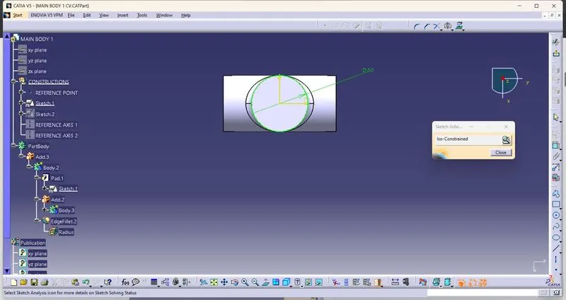
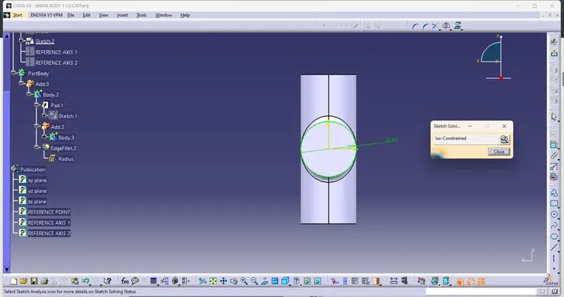
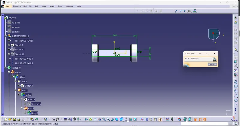
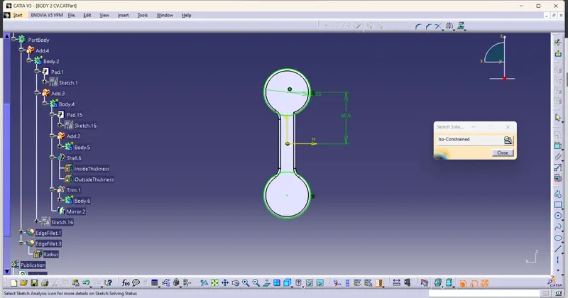
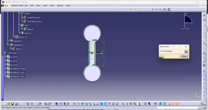
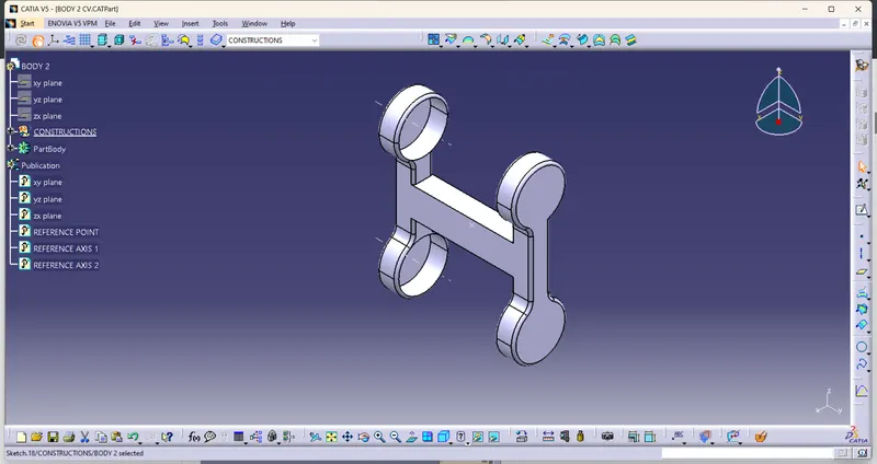
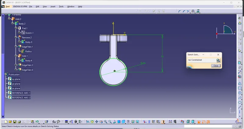
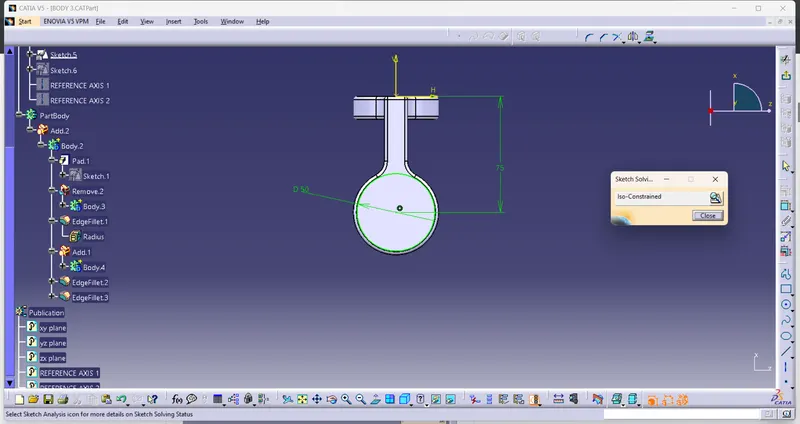
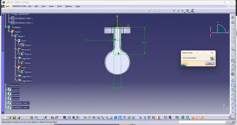
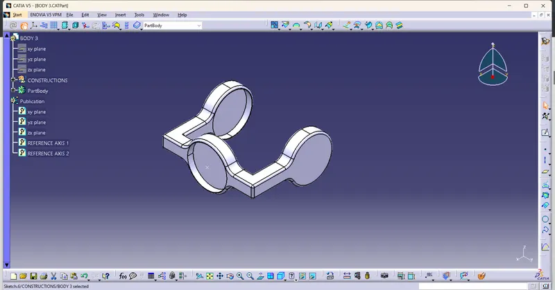
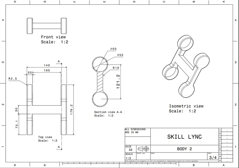
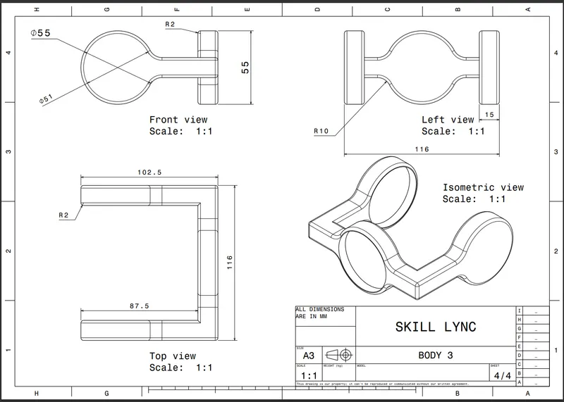
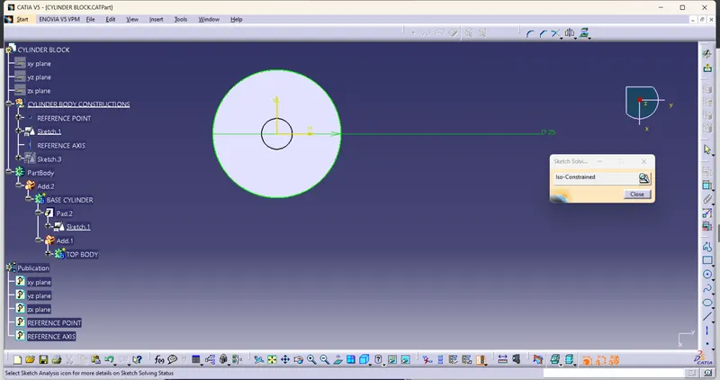
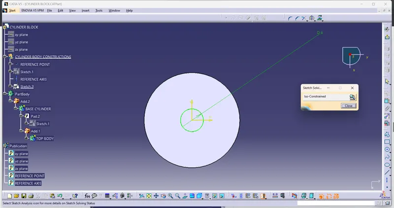
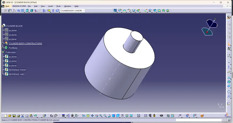
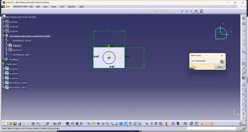
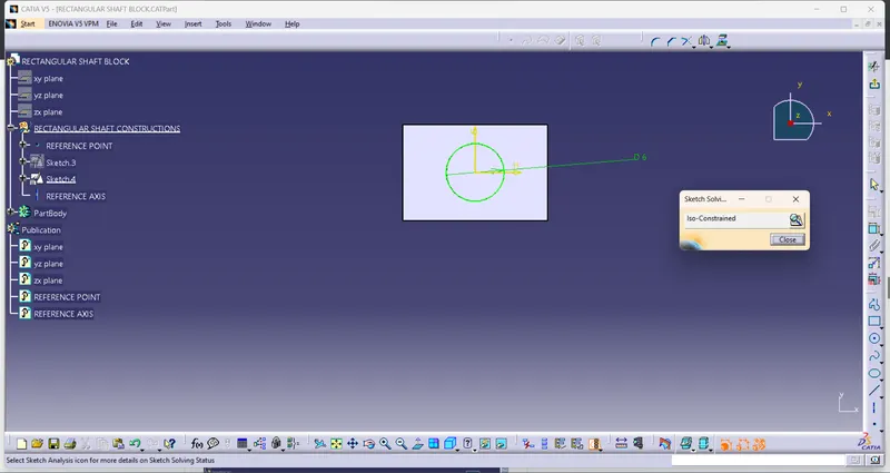
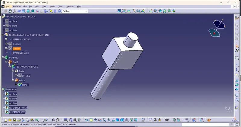
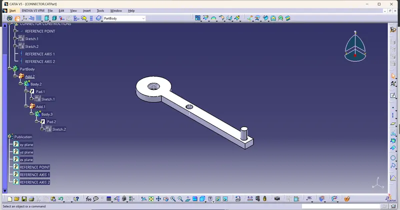
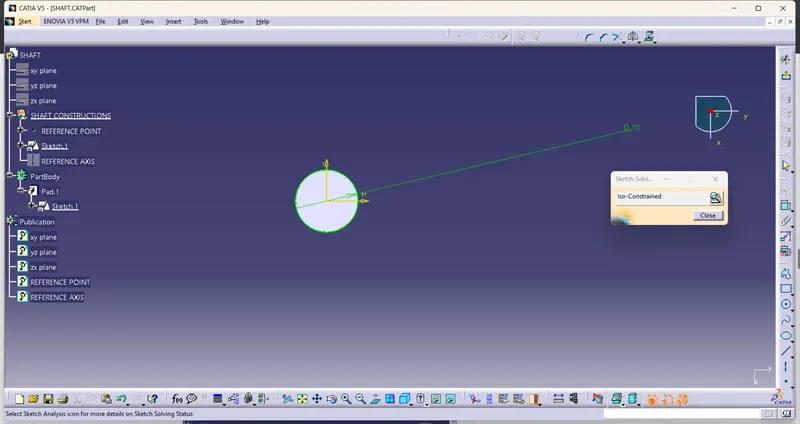
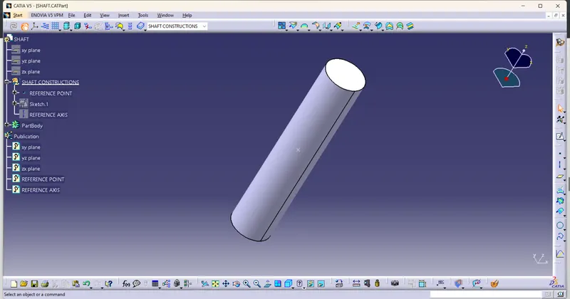
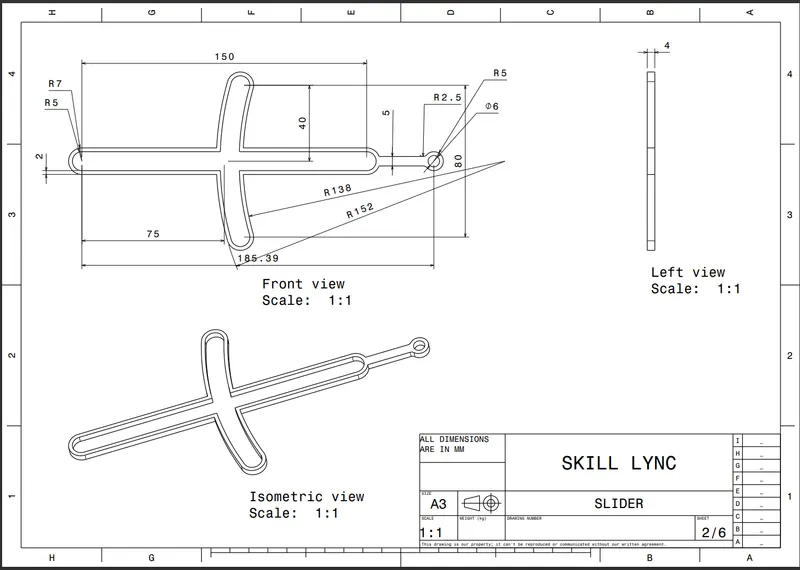
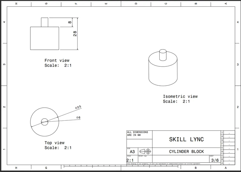
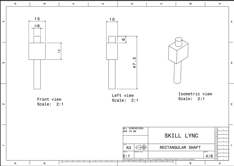
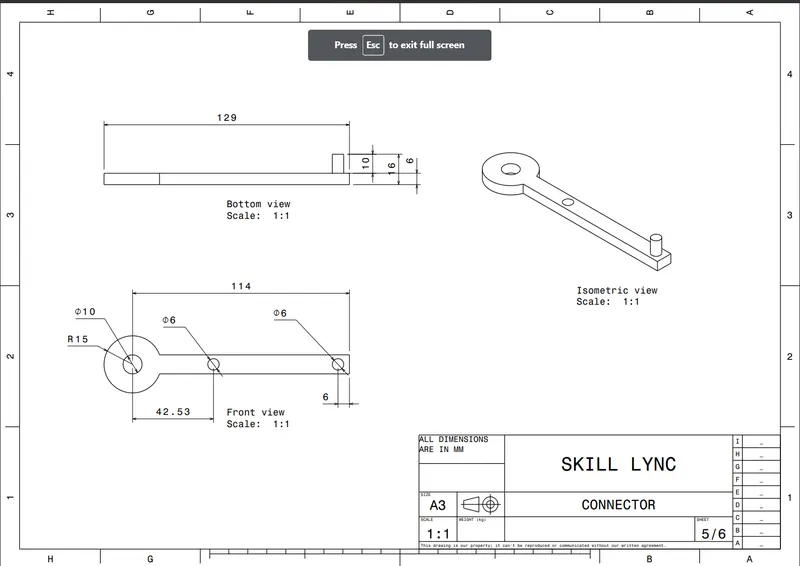
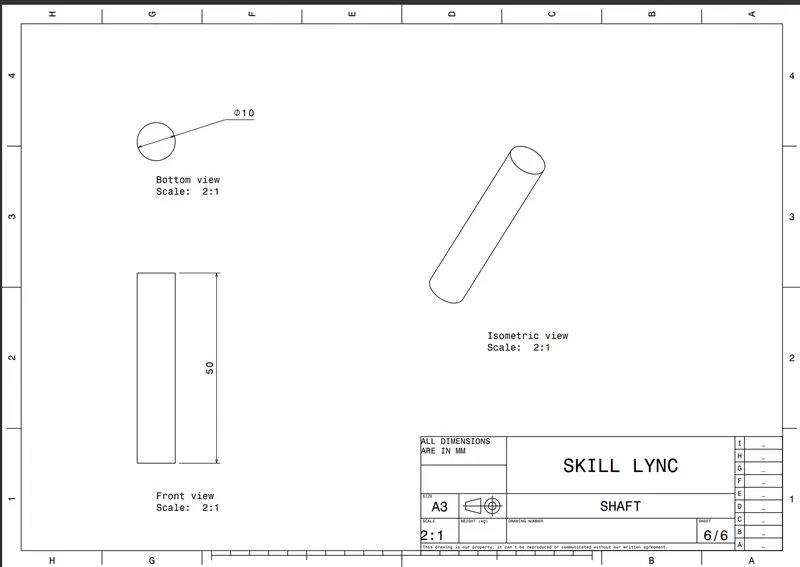
- Create a point 0 and select a poistioned sketch as per given dimensions draw a all parts and convert into solid through part design .
- All sketches are to be iso-constrained them .If they iso constrain the lines are in green colour.
Assembly Desisgn :
- It is define as join the individual parts into one part to ease for manufacturing it can be done through computer aided drawing .
- in assembly design create a product and select the option of existing components import it .
- Create a part from part command taken as reference coincide the base part to it and fix them.
- In this create and publish the point and planes as per reference .
- Use the tools are coincide it is used for connect two parts in one line or path to connect.
- Use contact constrant to contact the surfaces fo both parts to fix .
- All parts are to be coincidee them.
- After coincide with every part we are to update them only they are connected or not we know it
- For drafting annotation if we give generate numbering from product tool bar .
- If all parts are assemble are not to be check through explode commad use that command .
- Explode means it is deassemble the parts after that if we click ulpdate all parts regin their positon if it is assemble
Drafting:
- first we are drawn a 2D drawing into 3D using sketcher and part workbenches.
- Take a reference as a that diagram and open a new file and select drawing inthe box.
- Set the values and standards for drawing ISO and sheet was A3 and dimensions are 297x420mm.
- All dimesions are in mm .
- select views inthe tool bar and click on front view and select from refernce 3d drawing for part files or assembly .
- Select the projection plane inthe views bar and adapt the another views from the parent diagram .
- Given the dimesions as per given diagram.
- we use the ballon command to parts of the assembly .
- save inthe save management folder drawing sheet.
- save as pdf for sharing purpose both are save in one folder for usage.
Cv joint:
constructions:
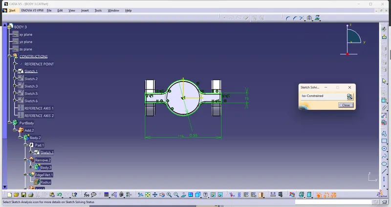
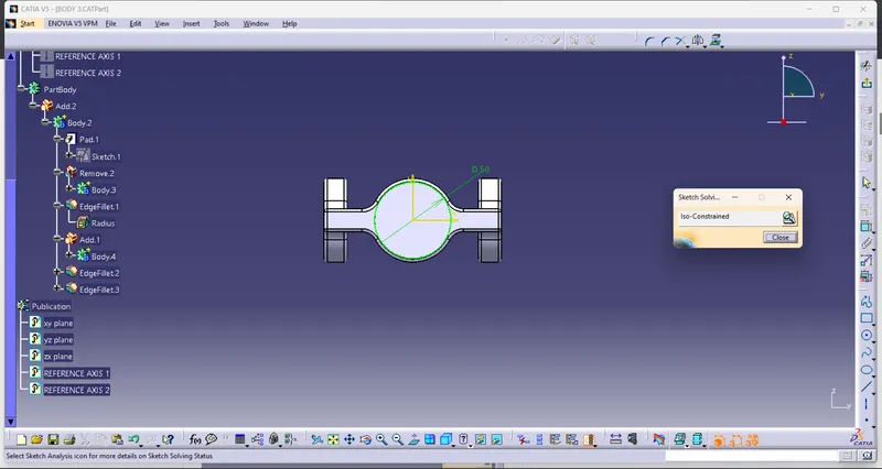
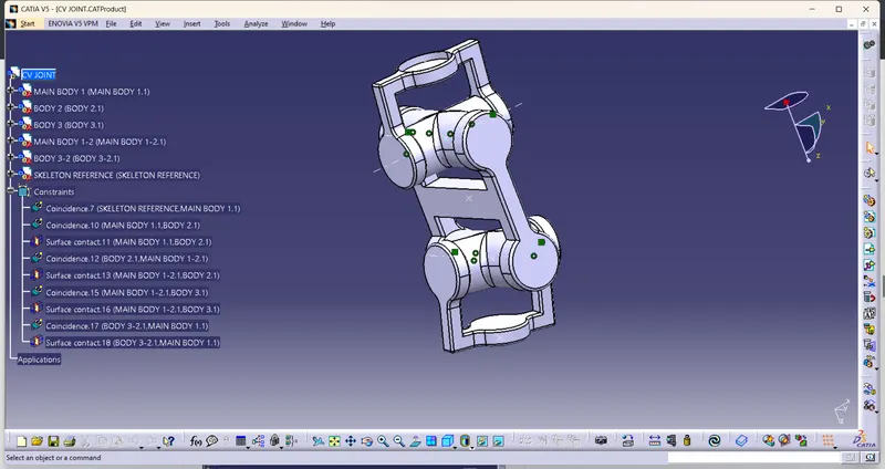
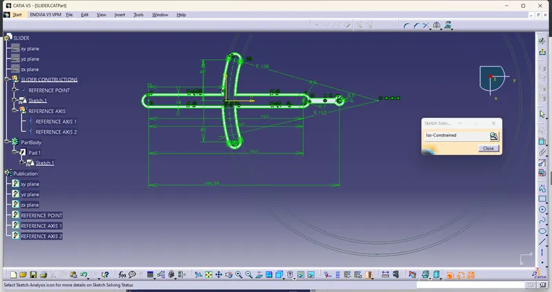
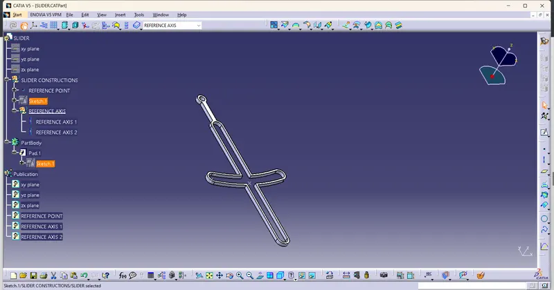
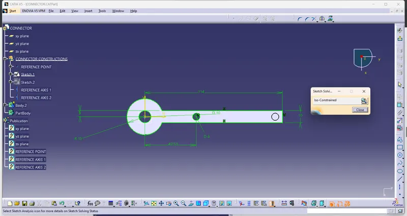
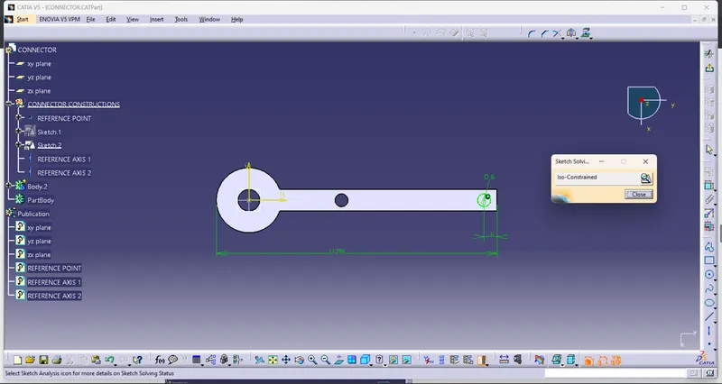
- Create a point 0 and select a poistioned sketch as per given dimensions draw a all parts and convert into solid through part design .
- All sketches are to be iso-constrained them .If they iso constrain the lines are in green colour.
Assembly Desisgn :
- It is define as join the individual parts into one part to ease for manufacturing it can be done through computer aided drawing .
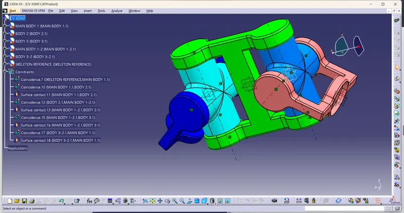
- in assembly design create a product and select the option of existing components import it .
- Create a part from part command taken as reference coincide the base part to it and fix them.
- In this create and publish the point and planes as per reference .
- Use the tools are coincide it is used for connect two parts in one line or path to connect.
- Use contact constrant to contact the surfaces fo both parts to fix .
- All parts are to be coincidee them.
- After coincide with every part we are to update them only they are connected or not we know it
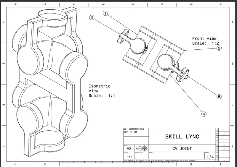
- For drafting annotation if we give generate numbering from product tool bar .
- If all parts are assemble are not to be check through explode commad use that command .
- Explode means it is deassemble the parts after that if we click ulpdate all parts regin their positon if it is assemble
Drafting:
- first we are drawn a 2D drawing into 3D using sketcher and part workbenches.
- Take a reference as a that diagram and open a new file and select drawing inthe box.
- Set the values and standards for drawing ISO and sheet was A3 and dimensions are 297x420mm.
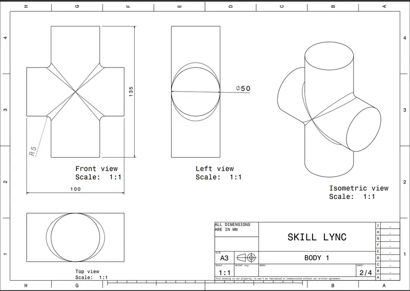
- All dimesions are in mm .
- select views inthe tool bar and click on front view and select from refernce 3d drawing for part files or assembly .
- Select the projection plane inthe views bar and adapt the another views from the parent diagram .
- Given the dimesions as per given diagram.
- we use the ballon command to parts of the assembly .
- save inthe save management folder drawing sheet.
- save as pdf for sharing purpose both are save in one folder for usage.