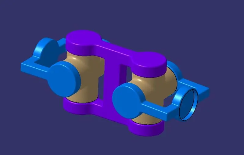
Week 10- Assembly Workbench
Aim:- To create part files for given 2D diagrams of the components and to assemble all the part files to make a product.
Assembly :-
Assembly modeling is a technology and method used by computer-aided design and product visualization computer software systems to handle multiple files that represent components within a product. The components within an assembly are represented as solid or surface models.
Quick Return Mechanism :-
1) A quick return mechanism is an apparatus to produce a reciprocating motion in which the time taken for travel in return stroke is less than in the forward stroke. It is driven by a circular motion source (typically a motor of some sort) and uses a system of link with three turning pairs and a sliding pair. A quick return mechanism is a subclass of a slider crank linkage, with an offset crank.
2) Quick return is a common feature of tools in which the action is performed in only one direction of the stroke, such as shapers and powered saws because it allows less time to be spent on returning tool to its initial position.
Procedure :-
1) Create a all sketch by using positioned sketch command.
2) Ensure that all the sketches in iso-constrained.
Drawing 1 :
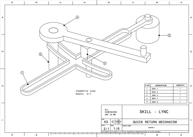
2D Drawing :
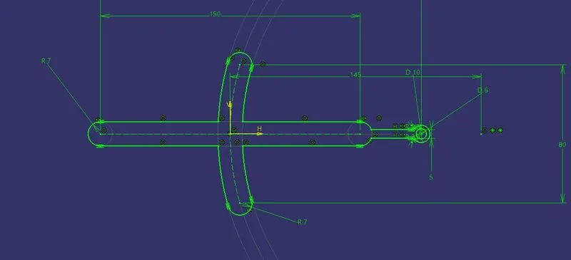
CAT Part :
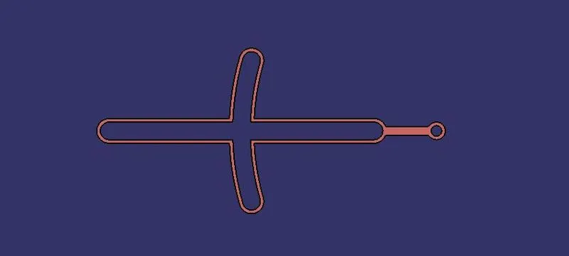
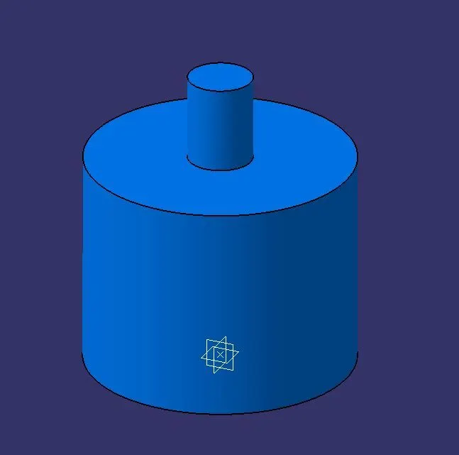
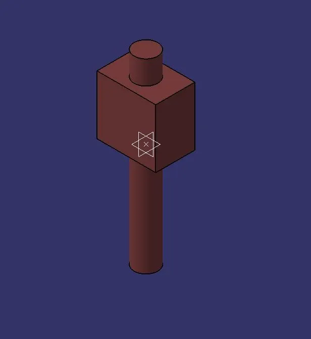
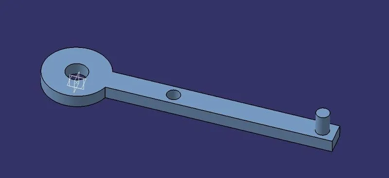
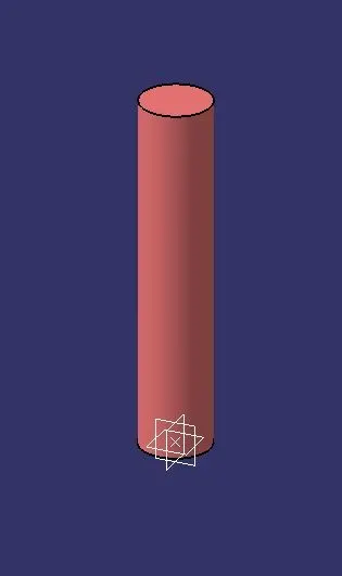
ASSEMBLE ALL CATPART :
1) Create a new CATproduct and insert all the above separate CATPART by using existing component command.
2) Create a reference elements for all catparts.
3) Add Reference elements like axis, points wherever we need
4) Use publication tool to make all the necessary elements like planes,points,axis to make visible.
5) Make the reference part fixed.
6) Now using Constrain, Offset tools assemble the each parts to one another.
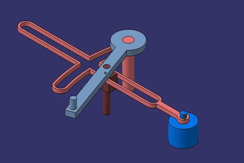
Drawing 2:-
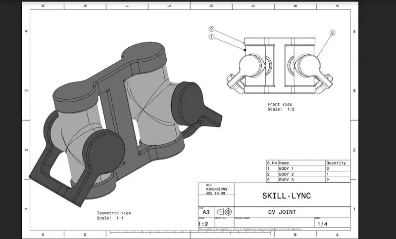
CV Joint:
Constant-velocity joints (also known as homokinetic or CV joints) allow a drive shaft to transmit power through a variable angle, at constant rotational speed, without an appreciable increase in friction or play. They are mainly used in front wheel drive vehicles. Modern rear wheel drive cars with independent rear suspension typically use CV joints at the ends of the rear axle halfshafts and increasingly use them on the drive shaft.
Function
Besides just holding the drive shaft in place, the CV joints also transfer power to the wheels from the transmission. Basically, they ensure that when you press on the gas, your wheels will turn. If the CV joint is not working properly, it may affect the way your vehicle handles. Often you will hear a popping or a clunk sound when shifting, which indicates something is wrong. If the joint breaks, it can stop the car from moving and can cause severe damage, making it essential component in your vehicle that needs to be kept in good condition.
Proceure of creating parts:
1. First create all parts of CV joints and QRM with help of drawings provided
2. All parts to be created separately in part work bench
3. After creating all parts individualy we assemble them together in single product in assembly workbench
4. Using constriants we assemble all parts together and create CV joint and QRM.
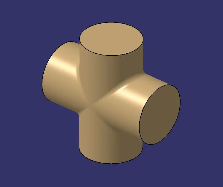
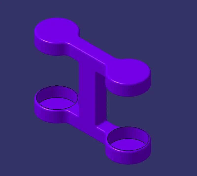
CAT Part:
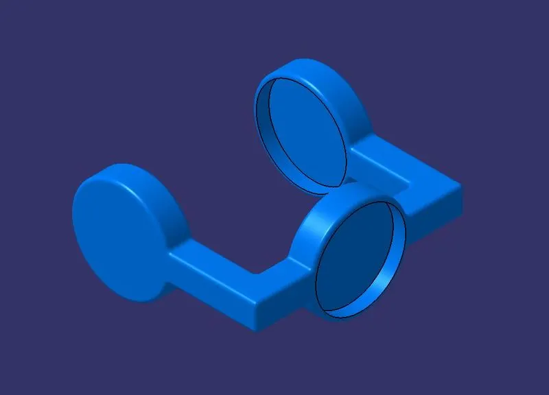
ASSEMBLE ALL CATPART :
1) Create a new CATproduct and insert all the above separate CATPART by using existing component command.
2) Create a reference elements for all catparts.
3) Add Reference elements like axis, points wherever we need
4) Use publication tool to make all the necessary elements like planes,points,axis to make visible.
5) Make the reference part fixed.
6) Now using Constrain, Offset tools assemble the each parts to one another.