Week 10- Assembly Workbench
MODEL 1- QUICK RETURN MECHANISM:
OBJECTIVE:
To create a quick return mechanism assembly from given drawing with all the parts.
BODY 1:
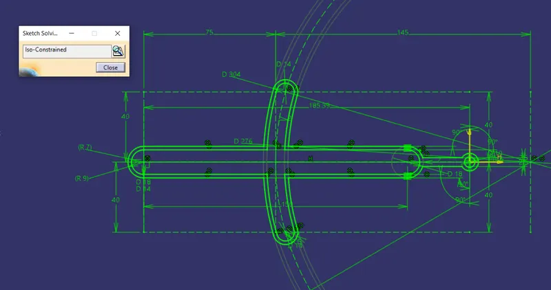
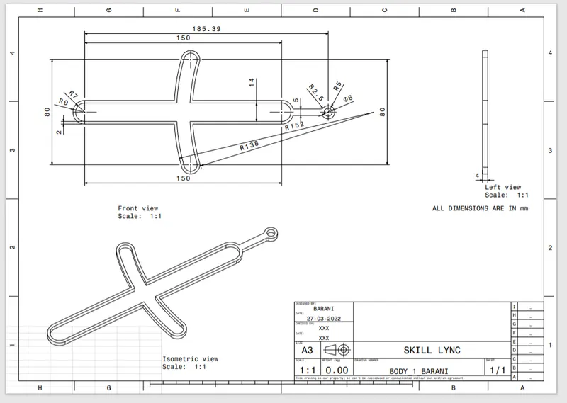
First I have created sketch from the drawing as per given dimensions with iso constrained.
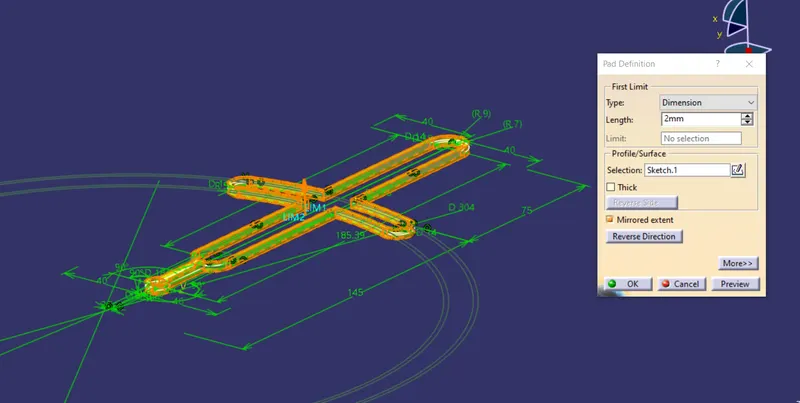
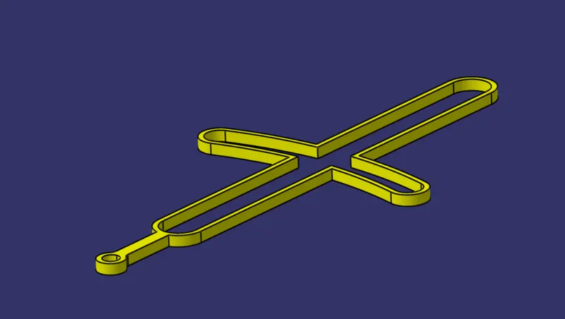
Then the sketch is paded with 2 mm in the part body.
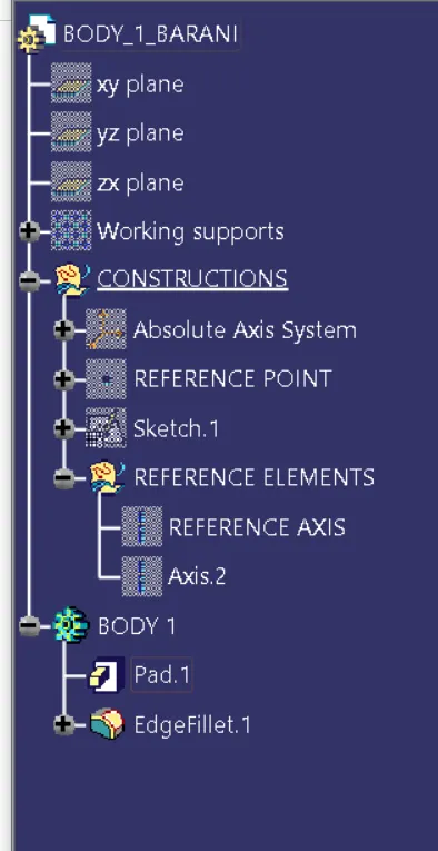
Tree Structure:
Drafting of body 1 is shown in the figure.
BODY 2:
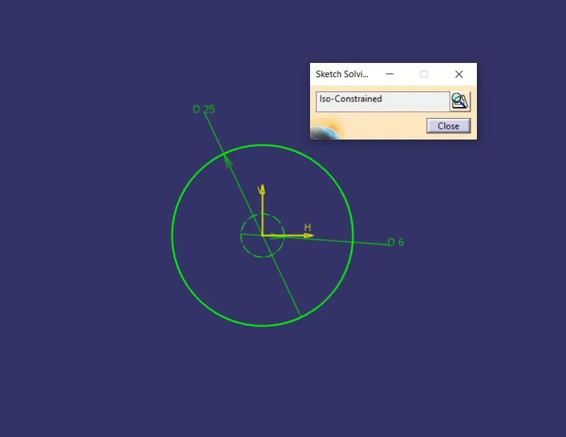
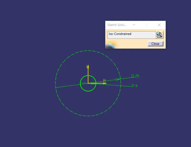
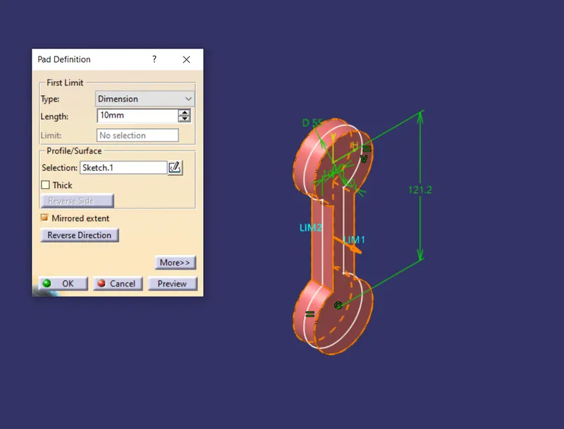
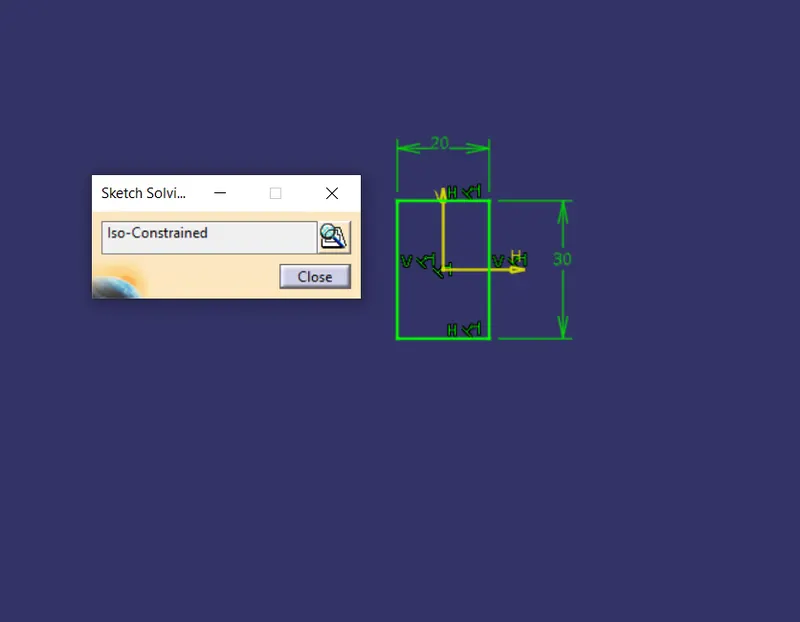
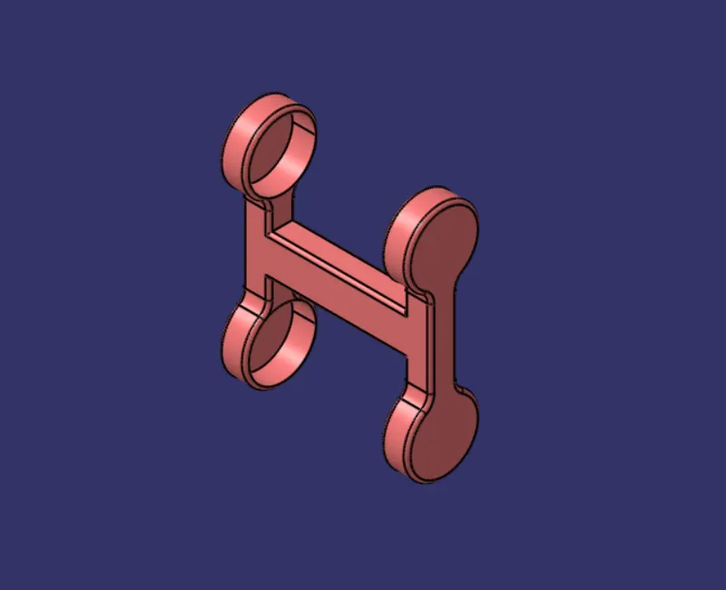
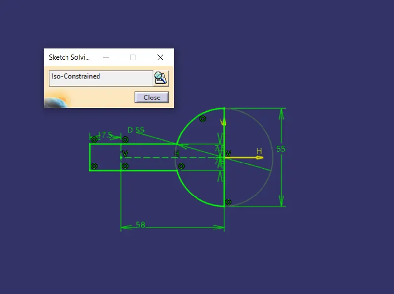
Sketch for body 2 is shown in the figure.
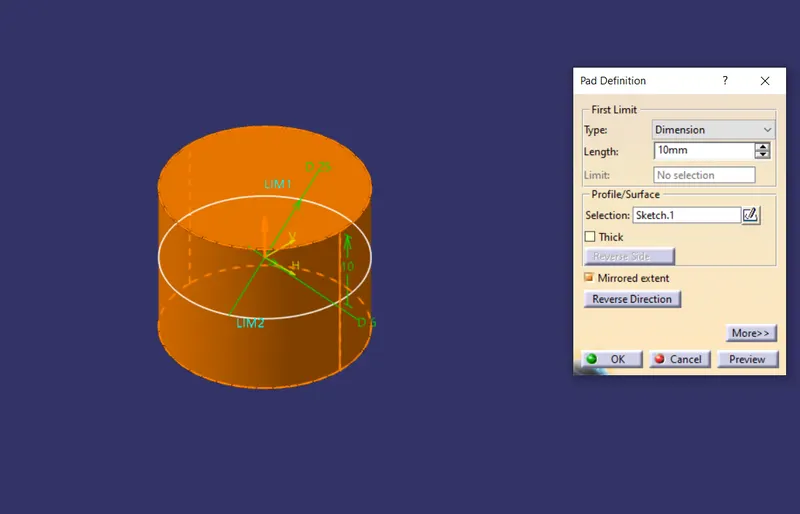
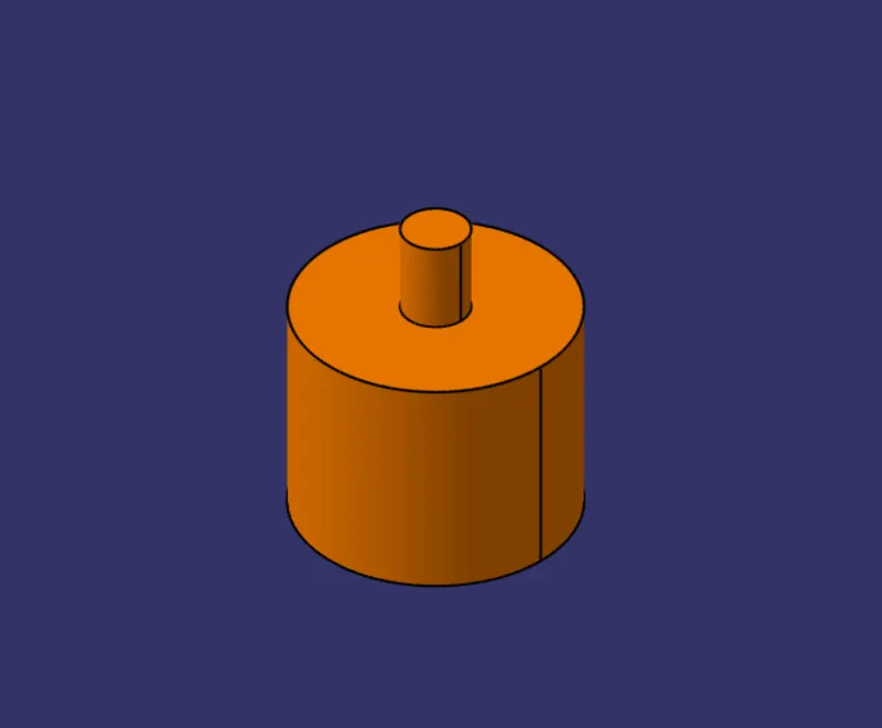
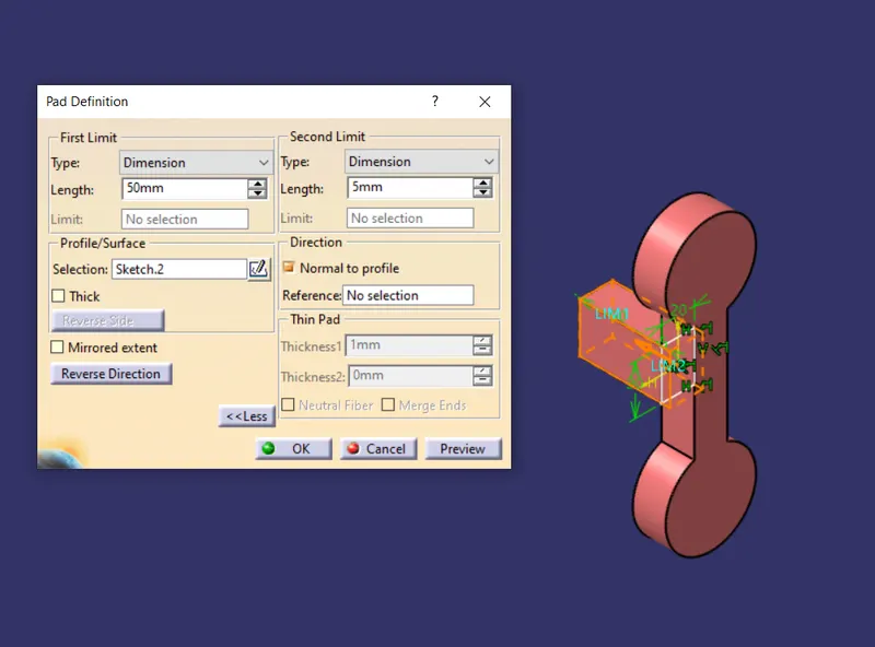
I have padded this sketch.
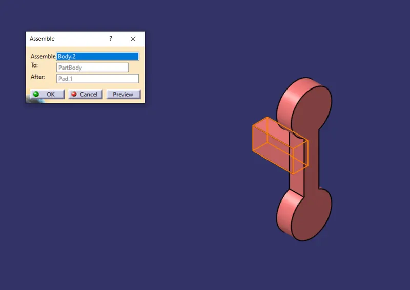
By using Boolean operation assembled this with previously created body.
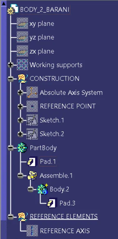
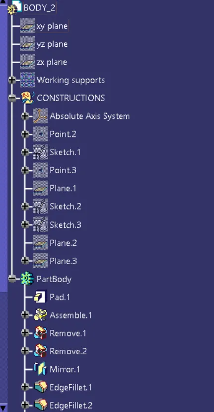
Tree Structure:
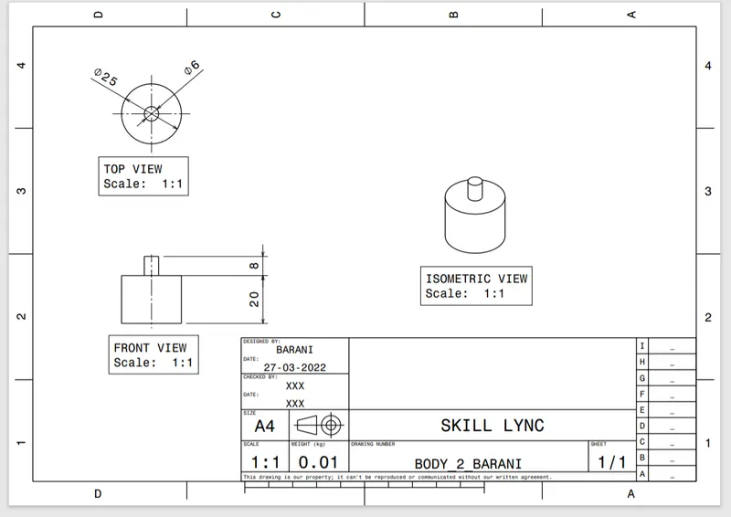
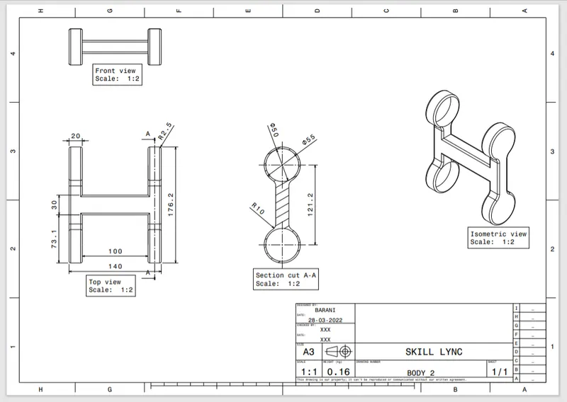
Drafting of Body 2 is shown in the figure.
BODY 3:
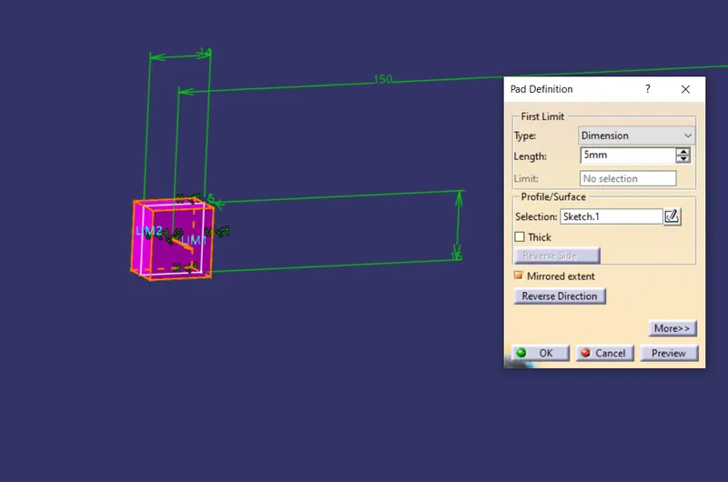
First created a rectangle and then padded it in the part body with 10 mm thick.
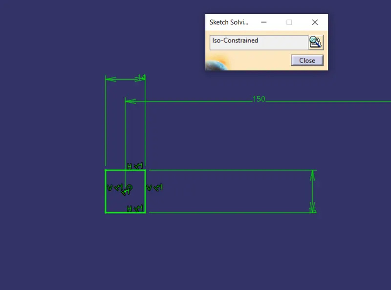
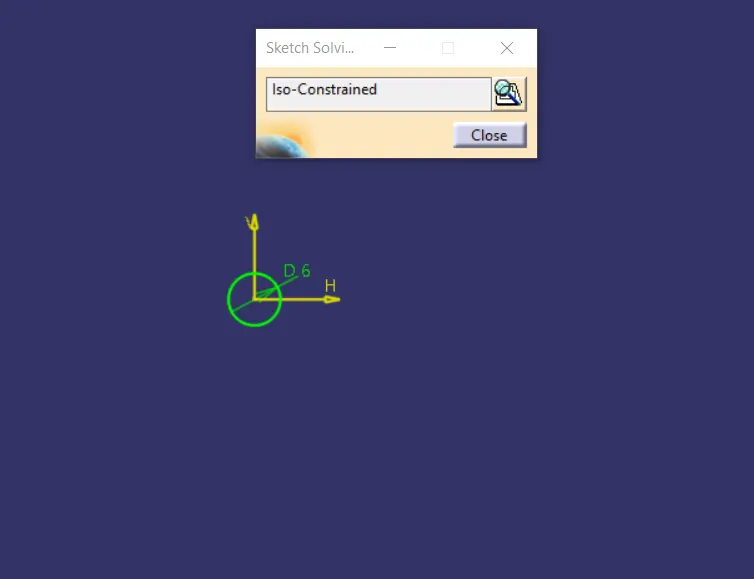
Created a circle on it for the rod.
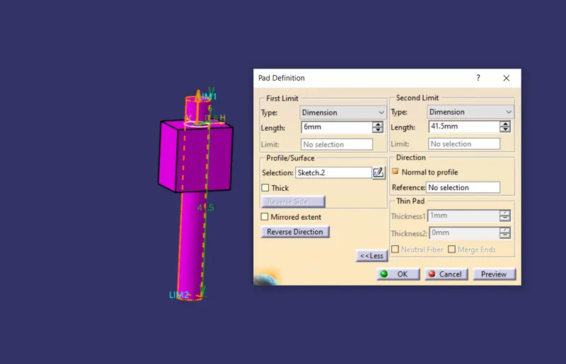
Padded this with 47.5 mm.
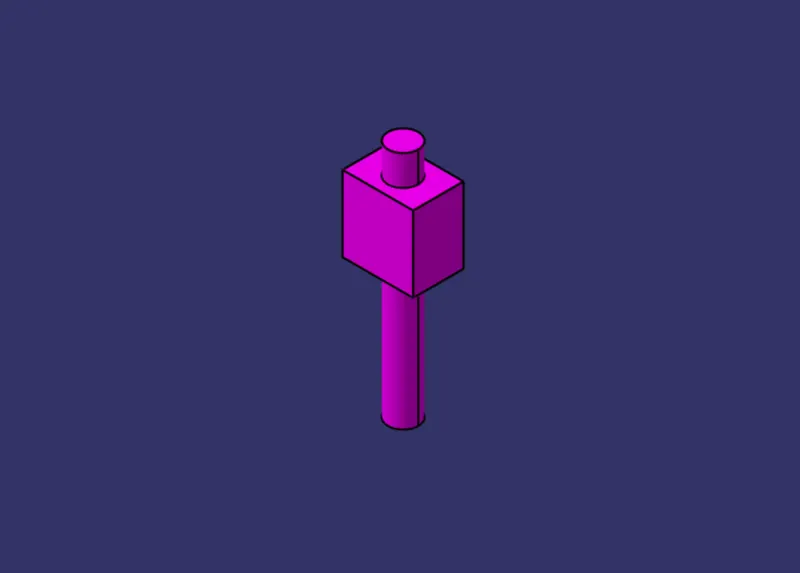
By using Boolean operation assembled this with rectangular body.
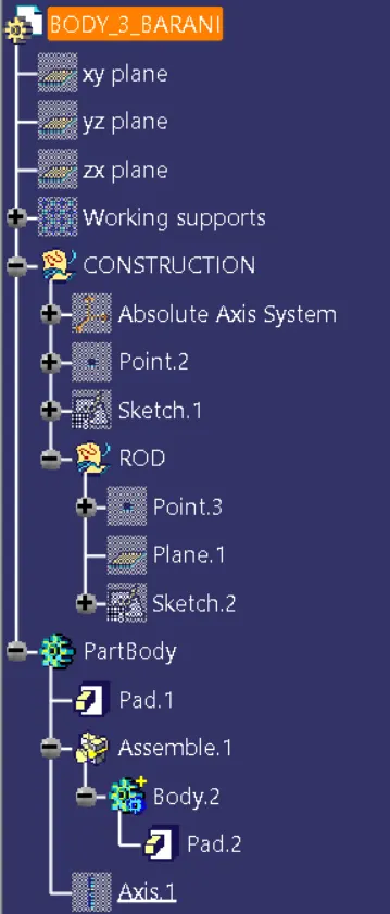
Tree Structure:
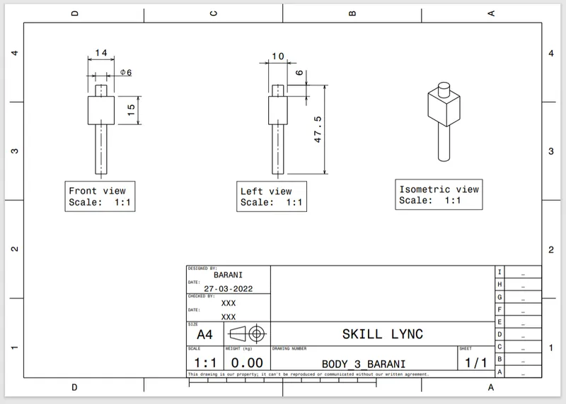
Drafting:
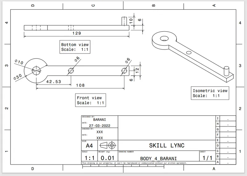
BODY 4:
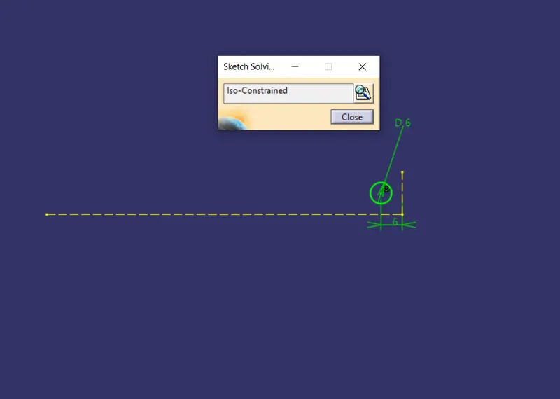
Created a below sketch from the drawing by using circle and rectangle command.
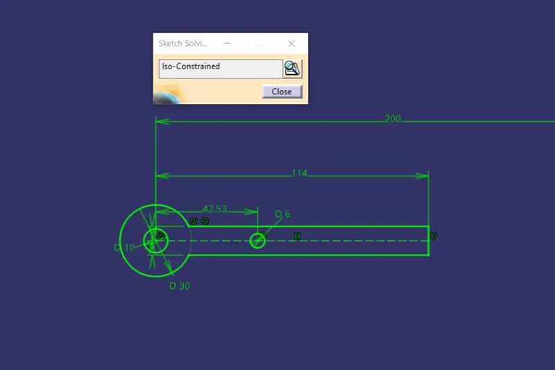
Padded this to 6 mm thick.
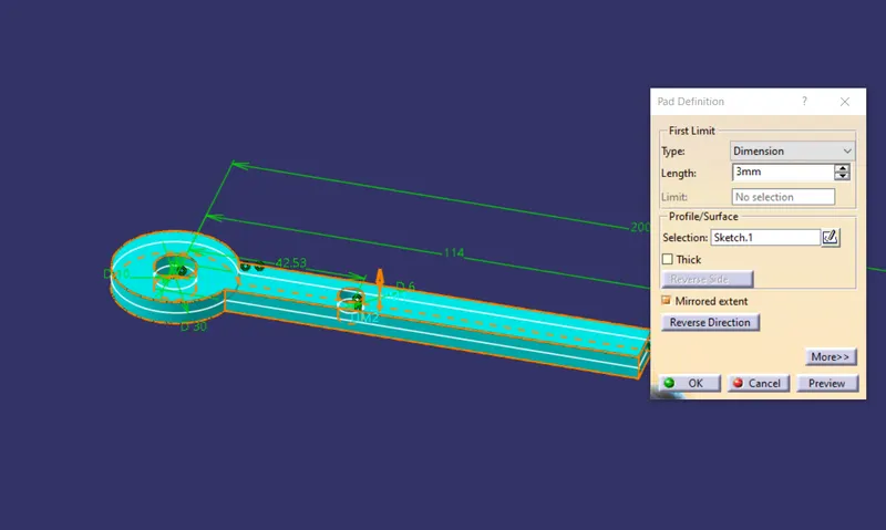
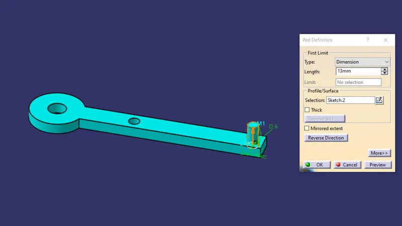
Created a circle for the pin
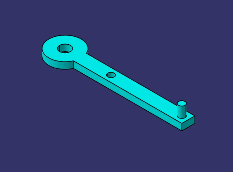
Padded this to 13 mm and then assembled with bottom part
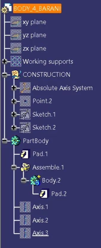
Tree Structure:
Drafting:
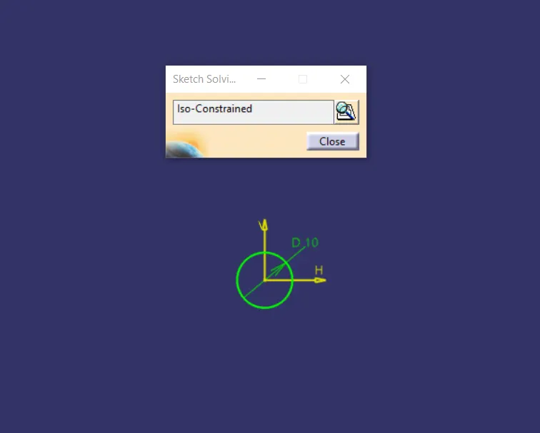
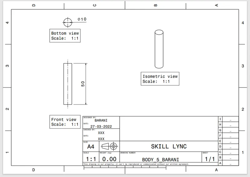
BODY 5:
Created a circle as shown in figure.
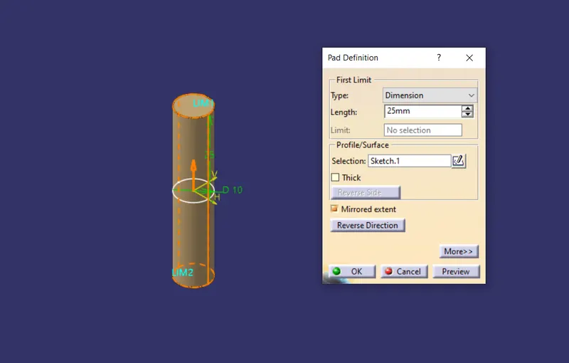
Padded this to 25 mm.
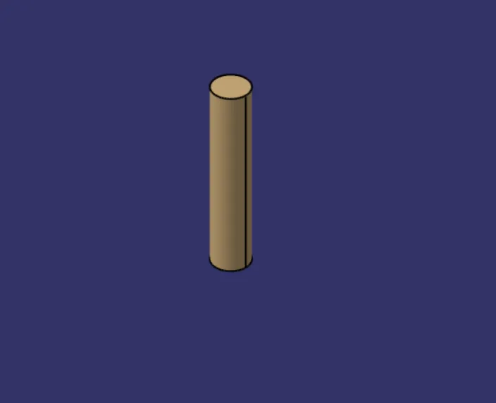
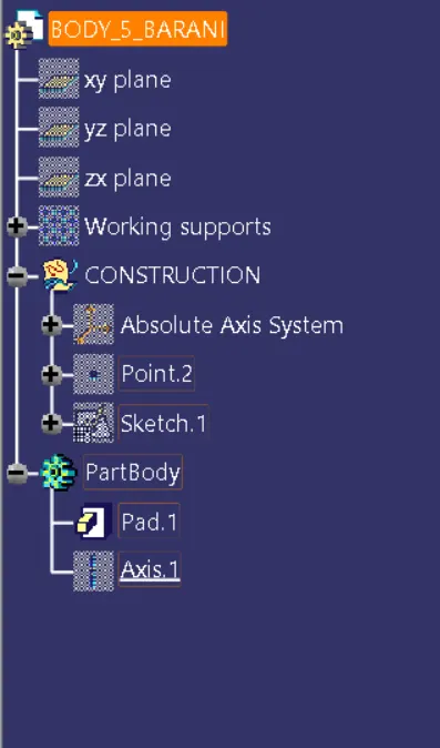
Tree Structure:
Drafting:
ASSEMBLY:
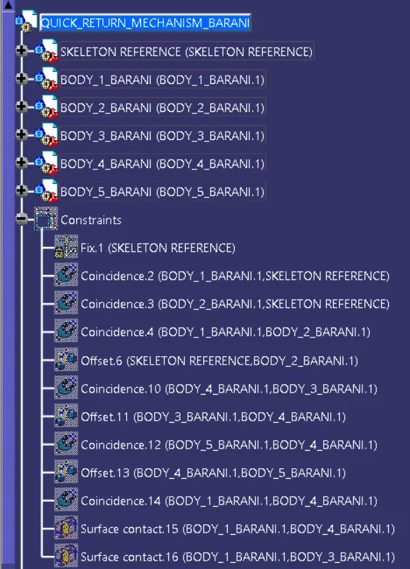
All the parts are created in the assembly workbench. Those are all assmbled together in assembly workbench. It is opened from File>New>Assembly. Named this as Quick Return Mechanism. Inserted all the parts by using Existing component>Click Assmbly name> Select Parts. Then I have created Reference for all the parts to assemble. BY using various constraints assembled all the parts as shown in the figure. Constraints used in this assembly are as follows:
1. Coincidence - Used to allign elements through any of the following: concentricity, coaxiality or coplanarity.
2. Offset - Used to allign elements with a distaance apart.
3. Surface Contact - Used to allign selected surfaces.
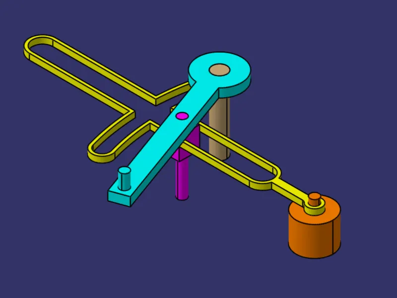
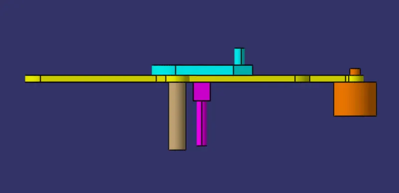
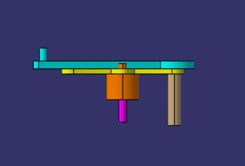
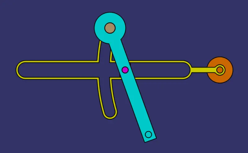
Different views of the assembly are shown in the figures.
Isometric view:
Front view:
Right side view:
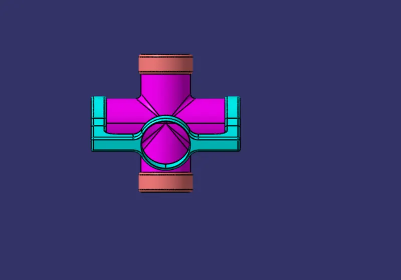
Top view:
Tree Structure:
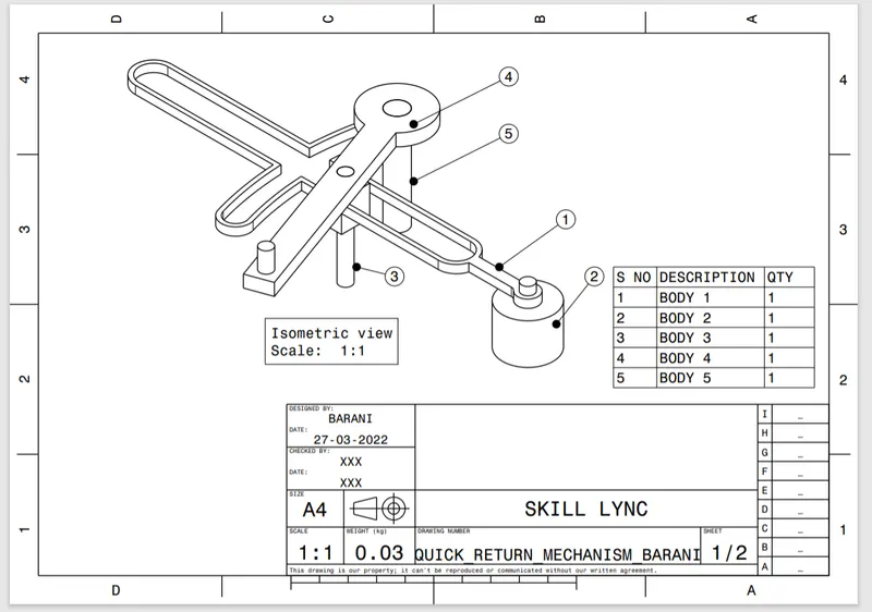
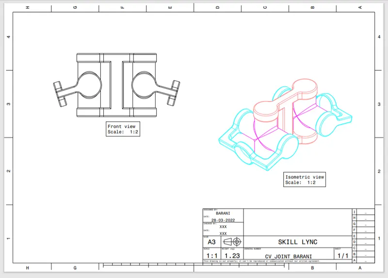
Drafting of assembly:
RESULT:
All the parts of Quick return mechanism has been created and assembled together by using assembly workbench. Also all the parts and assembly are drafted.
MODEL 2- CV JOINT:
OBJECTIVE:
To create and assemble the parts of constant velocity joint in catia assembly workbench.
BODY 1:
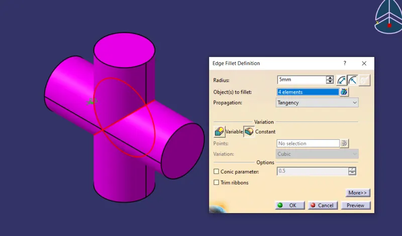
Created a circle dia of 50 mm.
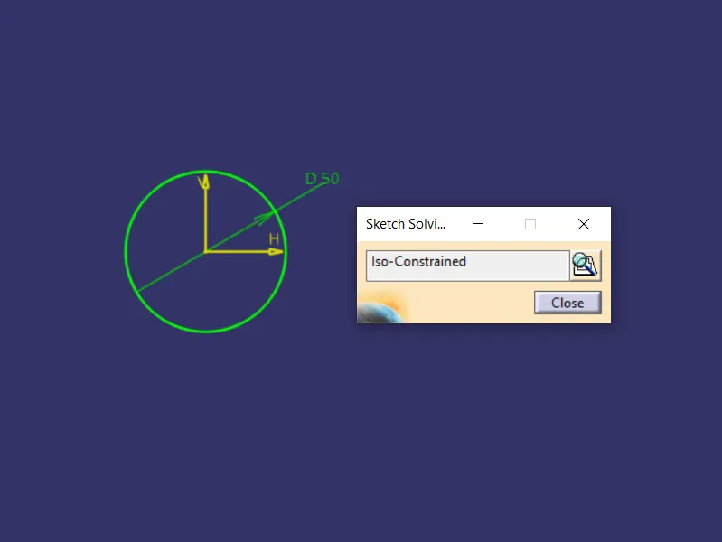
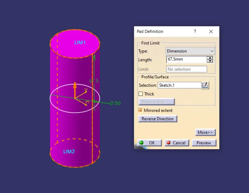
Padded this to 67.5 mm in part body.
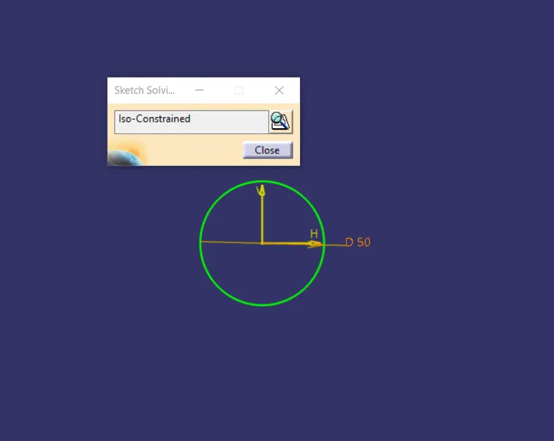
Again created a circle of same dimension for side part.
Padded of 67.5 mm as shown in the figure.
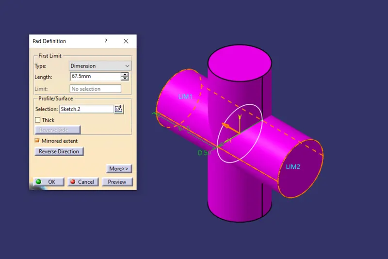
Assembled together by using boolean operation.

Given fillet of 5 mm to the joint edges.
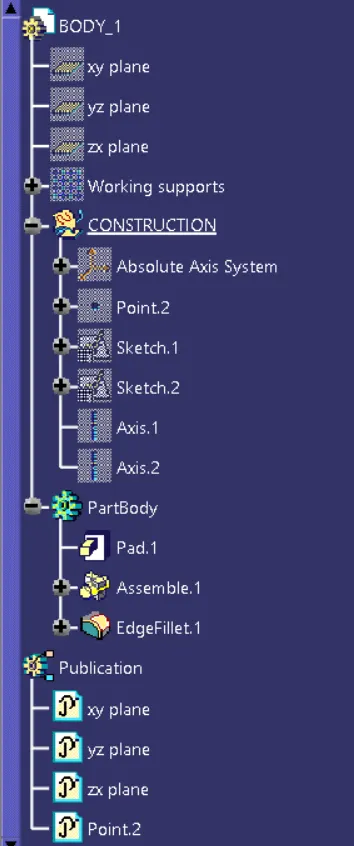
Tree Structure:
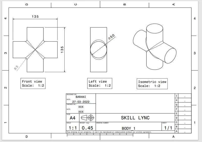
Drafting:
BODY 2:
Created a sketch by using circle and line as shown in figure.
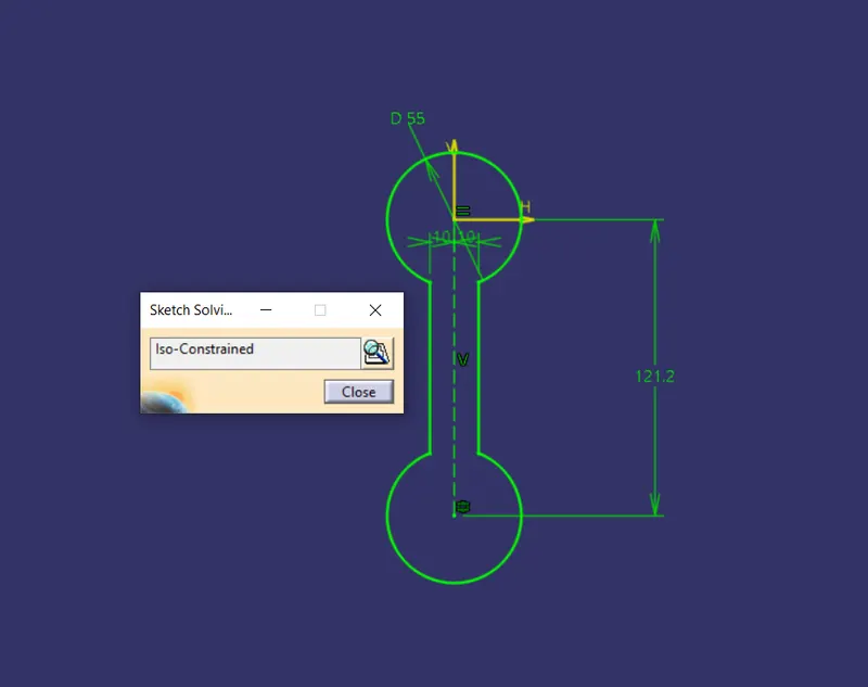
Padded this to 20 mm.
Created a rectangular profile.
Padded as shown in figure.
Assembled together by using boolean operation.
Created a sketch and pocketed it to remove the material.
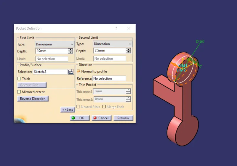
Copied that part and removed the same on the other side also.
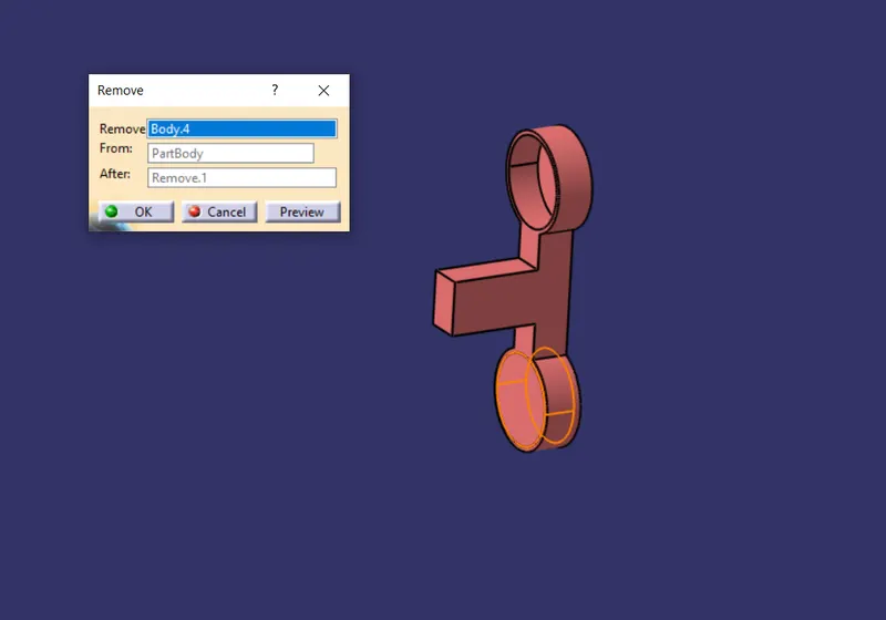
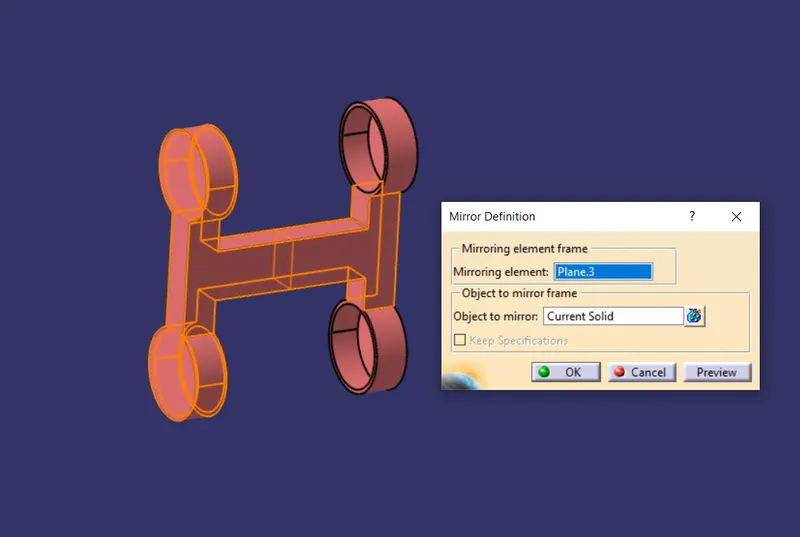
Then using mirror command created the other side.
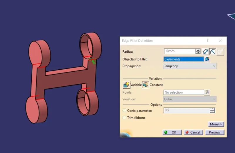
Edges are filleted.
Tree Structure:
Drafting:
BODY 3:
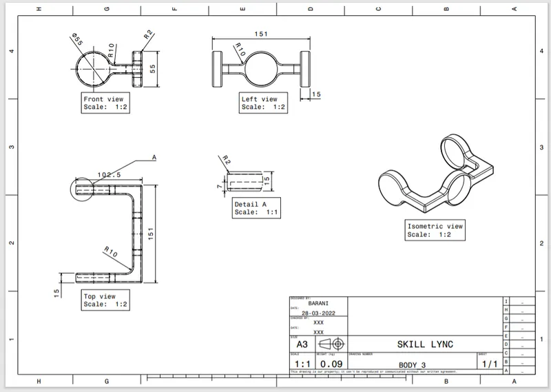
Created a sketch shown in below by using circle and line.
Padded this to 15 mm.
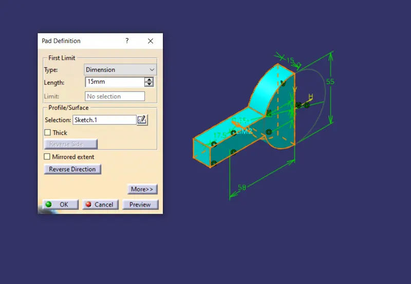
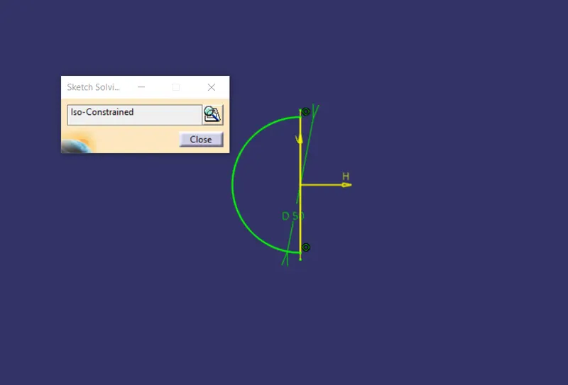
Created a semi circle to remove the material.
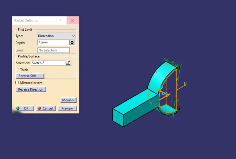
By using pocket command removed the part.
For side arm created a following sketch.
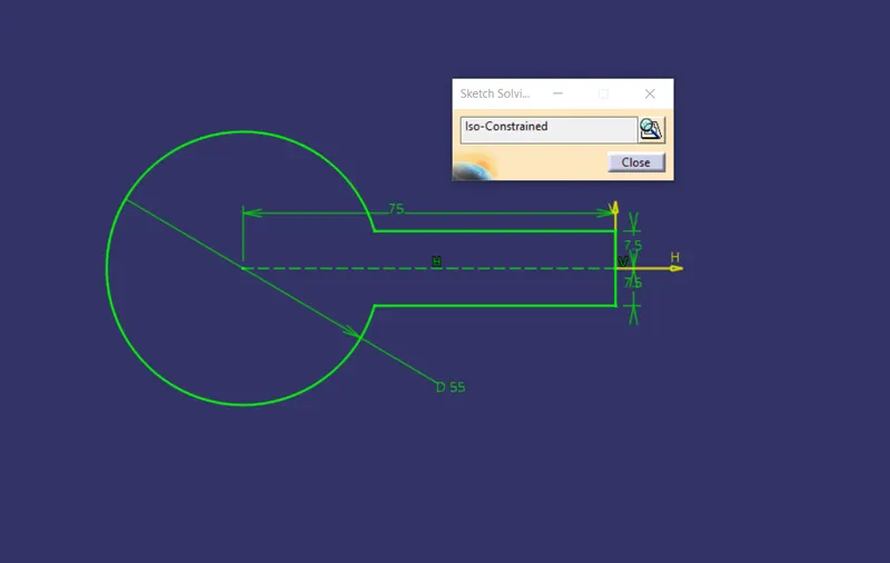
Padded this to 15 mm as shown in figure.
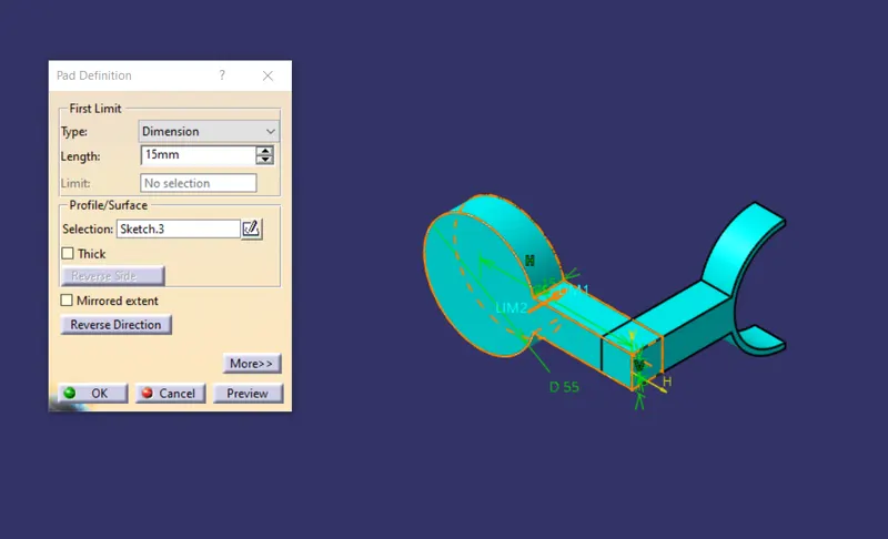
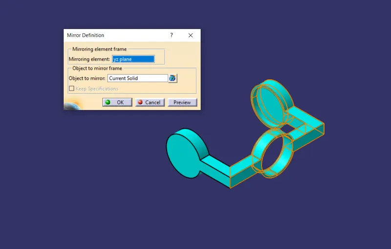
Assembled together by using boolean operation and then mirrored on the other side.
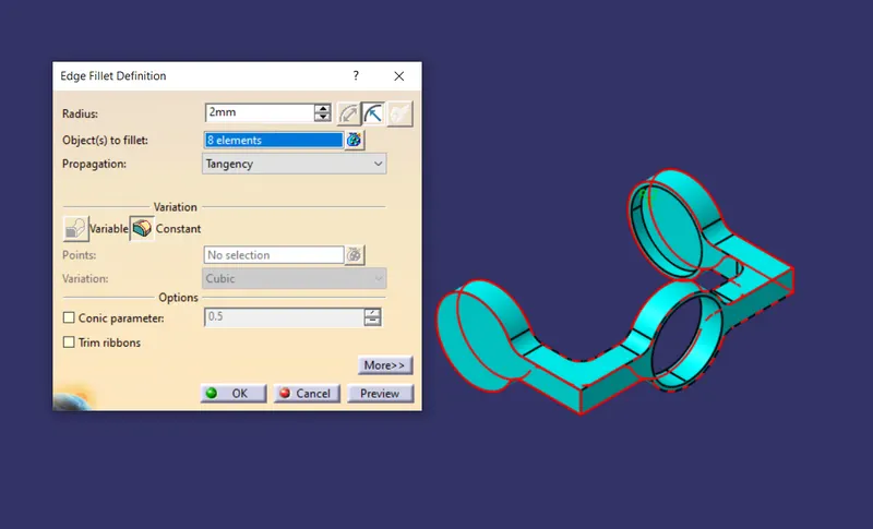
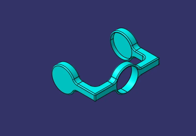
Given fillets as per the given drawing.
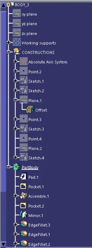
Tree Structure:
Drafting:
ASSEMBLY:
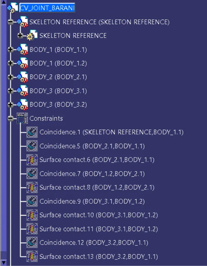
All the parts are created in the assembly workbench. Then assmbled together in assembly workbench. It is opened from File>New>Assembly. Named this as CV Joint. Inserted all the parts by using Existing component>Click Assmbly name> Select Parts. Then I have created Reference for all the parts to assemble. BY using various constraints assembled all the parts as shown in the figure. Constraints used in this assembly are as follows:
1. Coincidence - Used to allign elements through any of the following: concentricity, coaxiality or coplanarity.
2. Surface Contact - Used to allign selected surfaces.
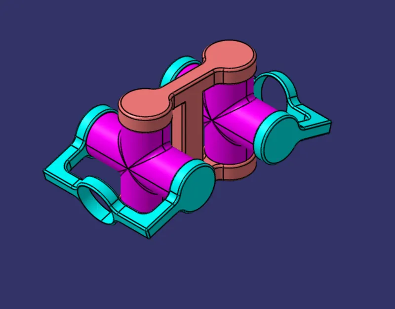
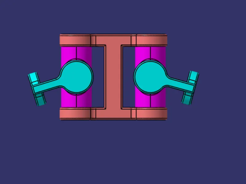
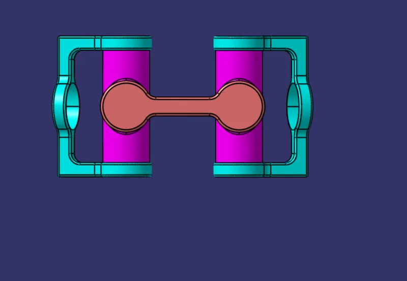
Different views of the assembly are shown in the figures.
Isometric view:
Front view:
Right side view:
Top view:
Tree Structure:
Drafting:
RESULT:
All the parts of CV joint has been created and assembled together by using assembly workbench. Also all the parts and assembly are drafted.