Week 10- Assembly Workbench
ASSEMBLY WORKBENCH
AIM:
- To create two assemblies with 2D diagrams of the components and to create the individual part files and then create a complete assembly of those part files in the assembly workbench
- Creation of drafting for the parts and assembly
PROCEDURE:
QUICK RETURN MECHANISM ASSEMBLY:
CREATION OF PART BODIES FOR ASSEMBLY:
BODY 1:
By considering the given dimensions the body has been created
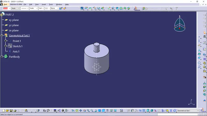
- At first the 2D sketch for the given body has been drawn in a positioned sketch
- PAD command is used to create the solid part from the 2D sketch
BODY 2:
By considering the given dimensions the body has been created
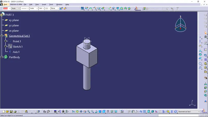
- At first the 2D sketch for the given body has been drawn in a positioned sketch
- PAD command is used to create the solid part from the 2D sketch
BODY 3:
By considering the given dimensions the body has been created
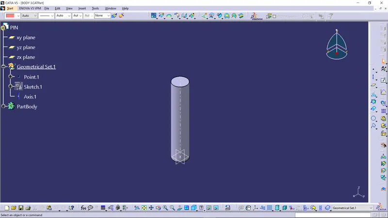
- At first the 2D sketch for the given body has been drawn in a positioned sketch
- PAD command is used to create the solid part from the 2D sketch
BODY 4:
By considering the given dimensions the body has been created
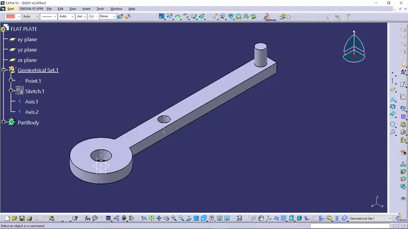
- At first the 2D sketch for the given body has been drawn in a positioned sketch
- PAD command is used to create the solid part from the 2D sketch
BODY 5:
By considering the given dimensions the body has been created
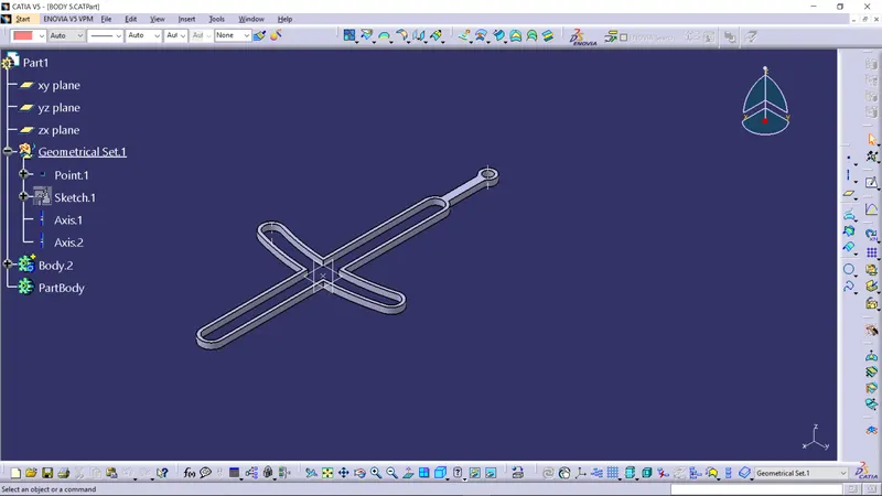
- At first the 2D sketch for the given body has been drawn in a positioned sketch
- PAD command is used to create the solid part from the 2D sketch
ASSEMBLY OF THE PART BODIES:
- Open the assembly workbench by START
- Created parts can be brought into assembly workbench by using the option EXISTING COMPONENT
- Using the option MANIPULATION the inserted bodies can be moved along the respective axis
- Using the CONSTRAINS TOOLBAR the constrains between the components were given
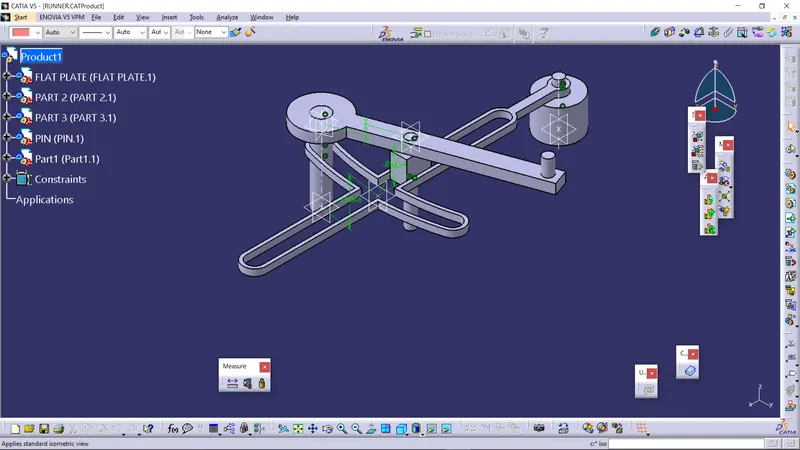
- The following constrains were given to create the assembly of quick return mechanism
- COINCIDENCE CONSTRAIN
- OFFSET CONSTRAIN
- While assembling the bodies make sure that the degrees of freedom are arrested in directions which dosent require motion
STEP 1: All the parts have been introduced into the assembly workbench
STEP 2:
- Body 1 and body 2 were assembled by creating an axis at the respective places
- Then they were aligned by both the axis by giving COINCIDENCE CONSTRAIN
- Then both the bodies were given OFFSET CONSTRAIN to bring both in contact
STEP 3:
- Now body 3 is brought in contact with the assembly by giving COINCIDENCE CONSTRAIN between the respective planes(zx plane)
STEP 4:
- Now body 4 is brought in contact with the assembly by coinciding the axis created at the respective positions
- Then both the axis were given COINCIDNCE CONSTRAIN and the axis were brought in contact
- Another axis is created in body 3 so that the slot in the body 4 also gets assembled with the coincidence constrains
STEP 5:
- Now body 5 is assembled again using coincidence constrain by creating axis at the respective positions
CONSTANT VELOCITY JOINTS(CV JOINT):
CREATION OF PART BODIES:
BODY 1:
By considering the given dimensions the body has been created
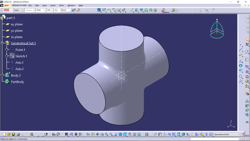
- At first the 2D sketch for the given body has been drawn in a positioned sketch
- PAD command is used to create the solid part from the 2D sketch
BODY 2:
By considering the given dimensions the body has been created
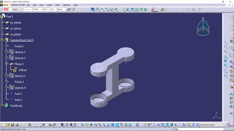
- At first the 2D sketch for the given body has been drawn in a positioned sketch
- PAD command is used to create the solid part from the 2D sketch
- Then remove operation is performed to create the cavity in the body
BODY 3:
By considering the given dimensions the body has been created
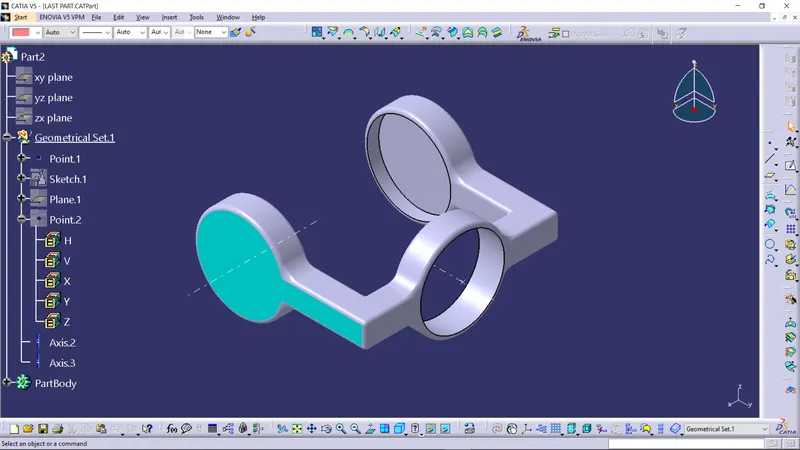
- At first the 2D sketch for the given body has been drawn in a positioned sketch
- PAD command is used to create the solid part from the 2D sketch
- Then remove operation is performed to create the cavity in the body
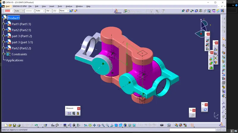
ASSEMBLY OF THE PART BODIES:
- Open the assembly workbench by START
- Created parts can be brought into assembly workbench by using the option EXISTING COMPONENT
- Using the option MANIPULATION the inserted bodies can be moved along the respective axis
- Using the CONSTRAINS TOOLBAR the constrains between the components were given
- The following constrains were given to create the assembly of quick return mechanism
- COINCIDENCE CONSTRAIN
- CONTACT CONSTRAIN
- While assembling the bodies make sure that the degrees of freedom are arrested in directions which dosent require motion
STEP 1:
- The bodies were introduced in the assembly workbench
- Except the body 2 the other bodies were introduced twice
STEP 2: Body 2 and body 1 were brought in contact by aligning the axis created at the respective positions using COINCIDENCE CONSTRAIN
STEP 3: Similarly another body 1 is also aligned with the same procedure
STEP 4: The body 3 is aligned with creating COINCIDNCE CONSTRAIN between the required aixs
CONCLUSION:
Thus the QUICK RETURN MECHANISM assembly and CV JOINT assembly were been created with the given 2D sketches.