Week 1 Stress Concentration on a Plate with hole
Aim:-
To design two plates with a hole or many holes model with the given dimentions and to determine the maximum deformation and stress developed in those two models in ANSYS-WORKBENCH.
Objective:-
- Compare the deformation and maximum stress developed on a structure steel model for the 2 cases.
- From an analysis standpoint, which of the design will you select.
- From a manufacturing standpoint, which of the design will you select.
Procedure:-
Plate Dimentions:
Case 1 Model:
Length= 300mm
Height= 120mm
Thickness= 30mm
Circular Hole at the center:
Diameter= 60mm
Boundary Conditions:
Plate fixed at left face.
Load of 500N on the right face.
Steps:-
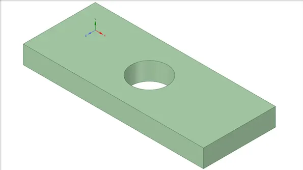
Initially we design the plate with a hole for the case 1 model in Geometry option in the space claim window.
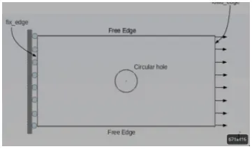
Case 1 Geometry Model:
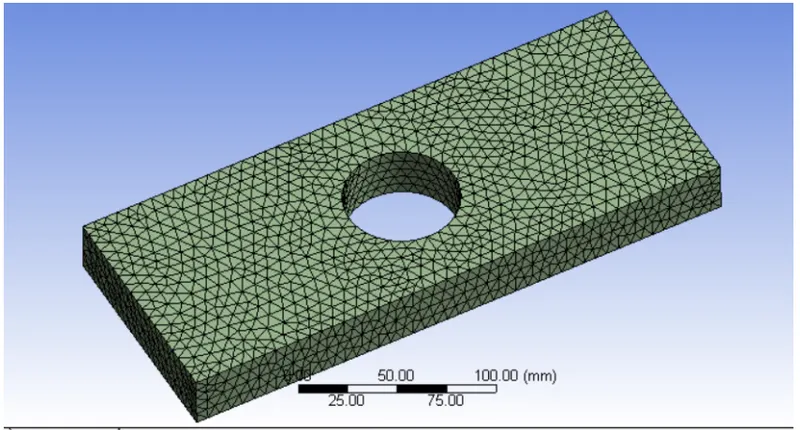
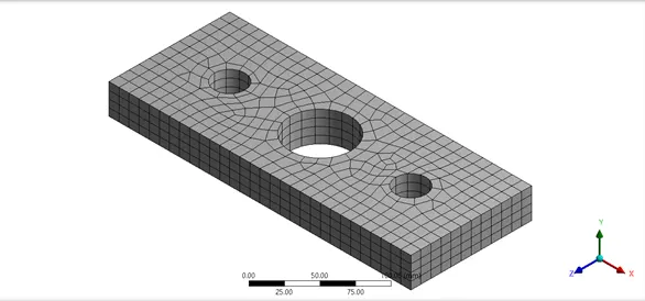
Then we open the model option and the mechanical modeller opens in which we will assume the material of the model to be structure steel.Ansd then we will mesh the model with an element size of 10mm.
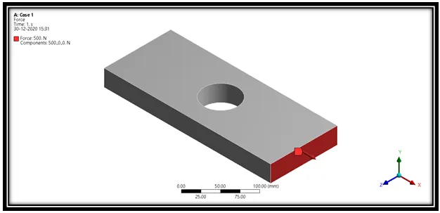
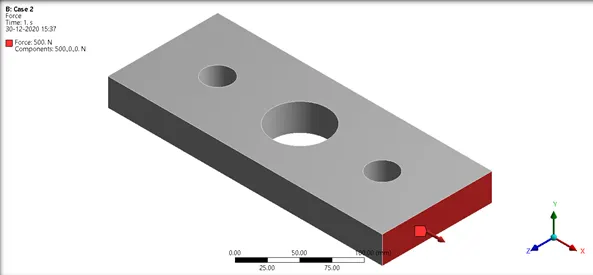
After meshing we will provide the fixed support for the model on the left side. And then we will provide the force of 500N on the right side of the model.
Now we will provide the solution parameters to the deformation and equivalent stess(von-mises).
Finally we will solve the model using the given boundary conditions.
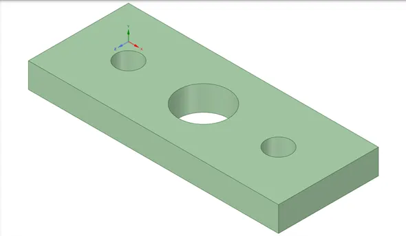
Case 2 model:-
Length= 300mm
Height=120mm
Thickness=30mm
Circular Hole at the center: Diameter=60mm
Smaller holes 90mm away from the center: Diameter=30mm.
The same procedure will be followed for the case 2 model.
Simulation Results:
Case 1 Model:
Total Deformation:
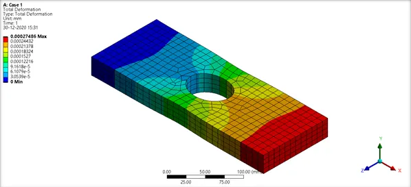
Maximum Deformation- 0.00027563mm
Equivalent Stress:
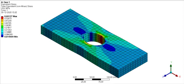
Maximum stress- 0.60137MPa
Case 2 model:
Total Deformation:
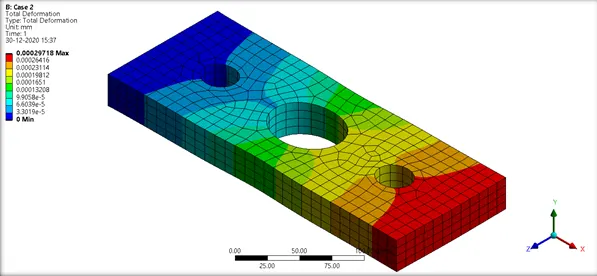
Maximum deformation- 0.00029617mm
Equivalent stress:
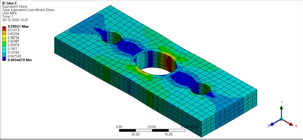
Maximum stress-0.58022MPa
From the above results we can see that the increase in the number of holes reduces the stress. The stress concentration can be reduced by avoiding the sharp edges and filleting the edges and with larger fillet diameter.
Analysis Point of view:
The case 2 model is suggested since there is less stress concentration across the bodies and also there is reduction of weight. Here the generated stress is low as compared to the first design and there is slight increment in the total deformation but that is negligible.
Manufacturing point of view:
The case 1 mode is suggested becase of ease in design and the case 2 model has three holes to be drilled. so, we need more machining time to complete the job and so that is the reason for selecting the case 1 model design.