Week 1 Spur Gear Challenge
Objective 1:
A torque of 10 Nm is applied by the driven gear. Find the Equivalent stress, Total deformation and Stress intensity & possible failure location in the following cases.
Table 1:
| Case | Gear Material |
| Case 1 | Cast Iron |
| Case 2 | Cast Steel |
| Case 3 | Cast Bronze |
Objective 2:
With a detailed report, conclude which material would be recommend based on these results.
CAD Model Details:
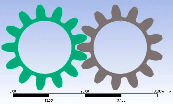
CAD model is same for all the cases.
13 tooth spur gears.
Material Properties:
| Case | Gear Material | Young's Modulus | Poisson's Ratio | Yield Strength | Ultimate Strength |
| Case 1 | Cast Iron | 8944 Mpa | 0.26 | 79.81 | 141.4 |
| Case 2 | Cast Steel | 203000 Mpa | 0.3 | 349 Mpa | 505 Mpa |
| Case 3 | Cast Bronze | 86022 Mpa | 0.345 | 144 Mpa | 267 Mpa |
Meshing:
Same mesh properties used in all cases.
Mesh Type: Tetrahedron
Mesh Size: 1 mm
Quality of Mesh: Medium
Boundary Condition / Connections:
Same Boundary Condition used for all cases.
Contacts:
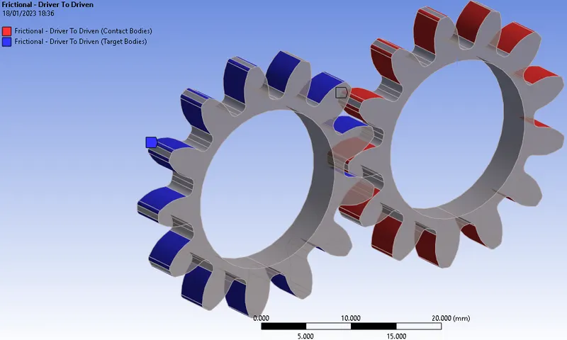
Frictional Contact established between highlighted surfaces.
Frictional coefficient - not considered.
Augumented Lagrange method used for approximation.
Interface Treatment "adjusted to touch" used to eliminate chattering.
Joint:
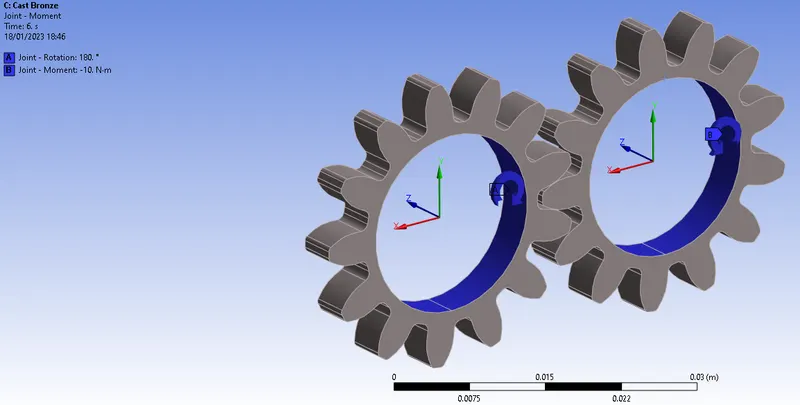
Revolute joint established between two gears. This arrests all Degrees of Freedom (DOF), except rotary motion along axis of rotation.
Loading Conditions:
Gears are allowed to rotate for 180 degress in 6 steps (each step is 30 deg).
A constant torque load of 10 N.m is applied on the gear toot to understand the stress levels on the gear teeth.
Analysis Results & Conclusion:
| Case | Gear Material | Yield Strength | Ultimate Strength |
Max Stress - Von Mises, From Simulation |
Max Stress Intensity, From Simulation | Max Contact Pressure, From Simulation |
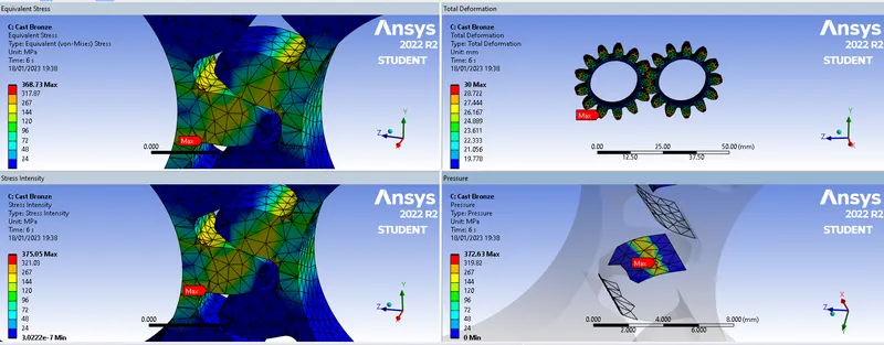
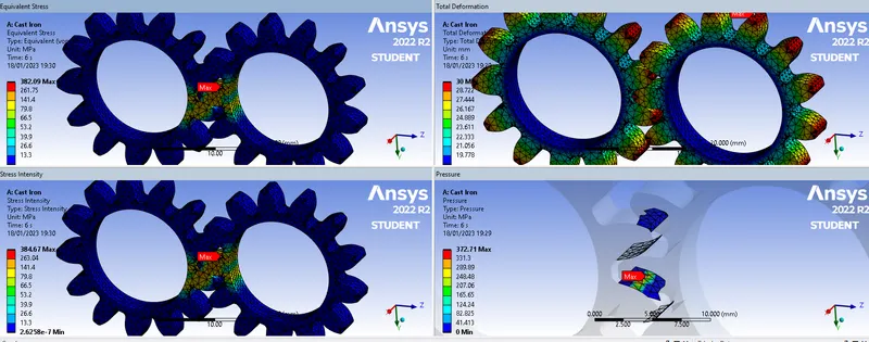
| Case 1 | Cast Iron | 79.81 Mpa | 141.4 Mpa | 382.09 Mpa | 384.67 Mpa | 372.71 MPa |
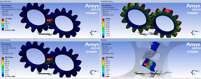
| Case 2 | Cast Steel | 349 Mpa | 505 Mpa | 377.8 Mpa | 382.22 Mpa | 366.29 Mpa |
| Case 3 | Cast Bronze | 144 Mpa | 267 Mpa | 368.73 | 375.05 Mpa | 372.63 Mpa |
For all the cases, (for a applied torque value of 10 Nm)
1. The stress levels are exceeding the yield strength of the material.
2. Maximum stress location is always at the base of the teeth.
3. The gear design, all the material considered in the simulation are incapable of transmitting the torque value (10 Nm). The gear design has to be changed.
4. Max deformation results will be irrelevant as the gears are free to rotate.
Case 1: Cast Iron
Case 2: Cast Steel
Case 3: Cast Bronze