Week 1 Spur Gear Challenge
Spur Gear Challenge
AIM:-
Run the simulation for the spur gear with different materials and find out the Total Deformation, Equivalent stress, and Stress Intensity.
OBJECTIVE:-
- To perform a Structural Analysis on the spur gear for all three cases with different materials such as Cast Steel, Cast Bronze, and Cast Iron.
- To add the required materials to the case set up from the Engineering data source.
- To find the location of the fracture, Where it occurs on the gear.
- To compare the simulation results for those three materials.
- To find out the stress intensity in the spur gear.
- To recommend the material based on the results.
PROCEDURE:-
1. Material Setup:-
To set up the material for the spur gear model. First, drag and drop the static structural analysis workspace into the project schematic from the analysis system.
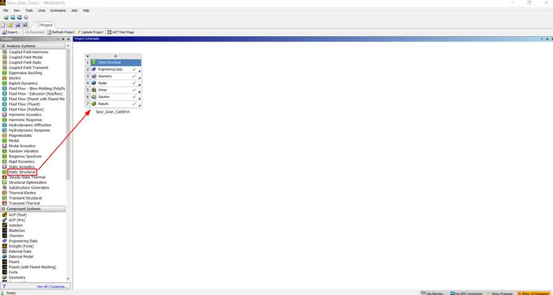
After deploying the static structural analysis system in the project schematic workspace, define the Engineering Data and geometry, To define the Geometry and Engineering Data, Right Click on the Engineering Data and click to edit, it will take to the Engineering Tab.
Now click on the "Click here to add a new material" option and name it as Cast Iron. After that define required properties for the material created, by double click on the properties and specifying values for those properties.
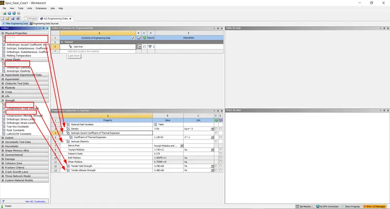
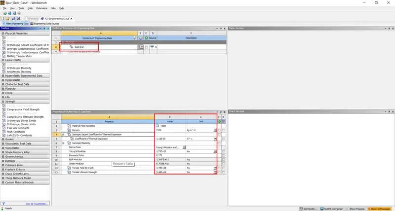
Create the other two material in the same way and define their property values.
Cast Iron -
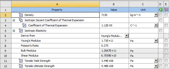
Cast Steel -
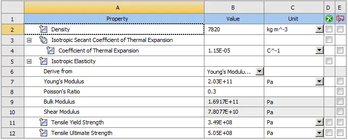
Cast Bronze -
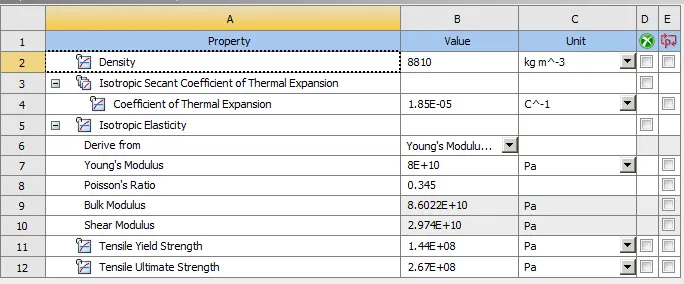
2. Geometry Setup:-
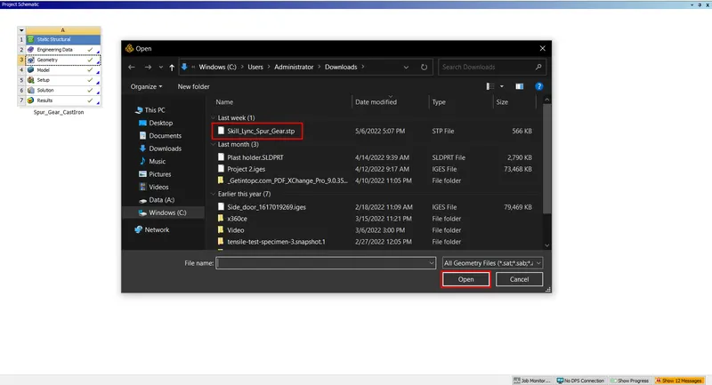
Next set up the geometry. To set up the geometry, Right-Click on the Geometry option > Import Geometry and then locate the .stp file of the geometry and click on open.
3. Case Setup:-
Next, define the model, Double click on the model, The Mechanical Workspace will open, we can set up the load cases for all three cases here.
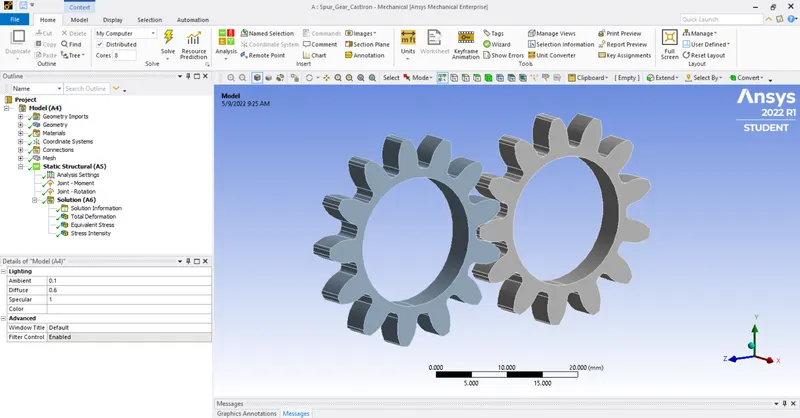
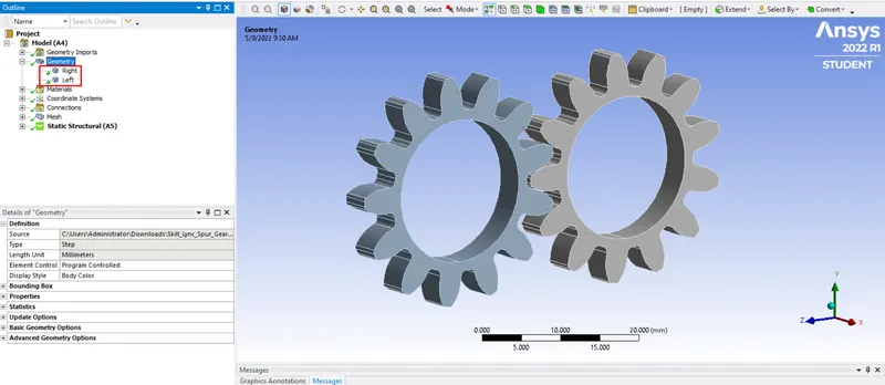
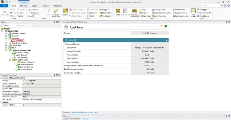
Rename both the gears as Right and Left accordingly. We can see here the material that is assigned to both the gears which is cast iron.
Defining Contact:-
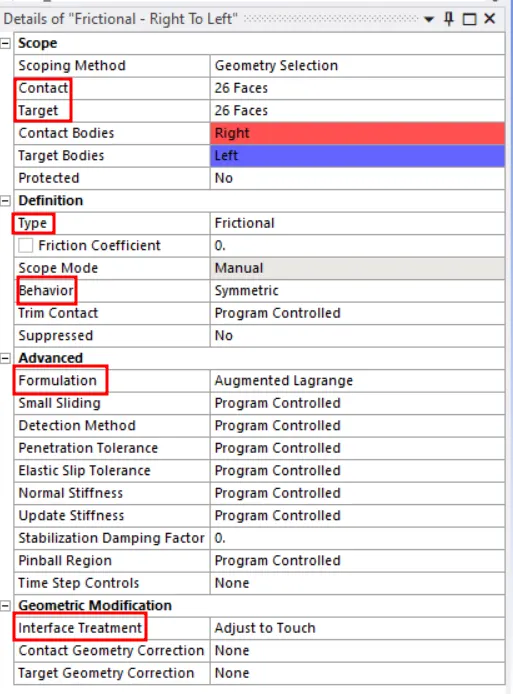
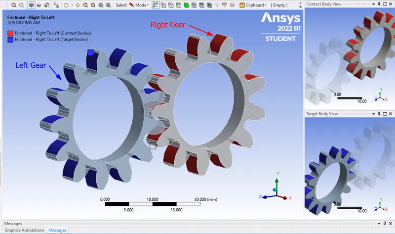
Select the faces of gear teeth one by one using ctrl+left click and since there are 13 teeth so total 26 faces are selected for each gear. The type of contact between the faces of driver and driven gear teeth is defined as frictional contact with contact bodies being right gear and target bodies being left gear. Augmented Lagrange formulation is chosen to minimize the interference errors. Interface treatment is chosen as adjust to touch to avoid penetration.
Creating Joint:-
After defining the contact, We have to deploy joints for the spur gear. To create a joints, Right Click on the Connections > Insert > Joint.
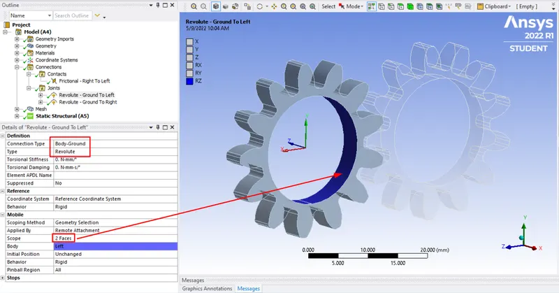
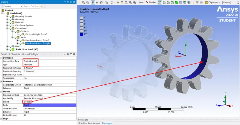
Meshing:-
After defining the joint in the connections panel, we have to define mesh for the spur gear. To define Mesh, Click on the Mesh > Give Mesh Size as 1mm. Right click on the mesh and select Generate Mesh option.
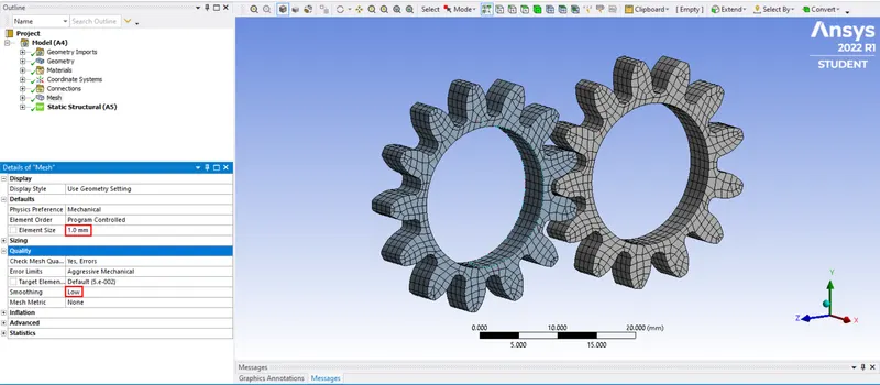
Defining Analysis Settings:-
Select all the steps using ctrl+left click and then give the values of the parameters as shown.
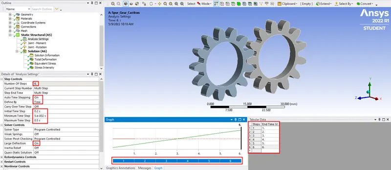
Defining Joint load:-
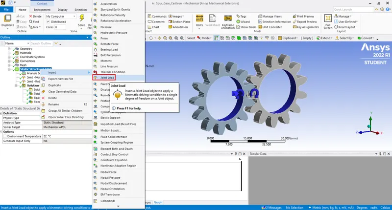
Create a two joints,One for Rotation and Other for Moment. To create Joint Loads, Right Click on the Static Structural > Insert > Joint Load.
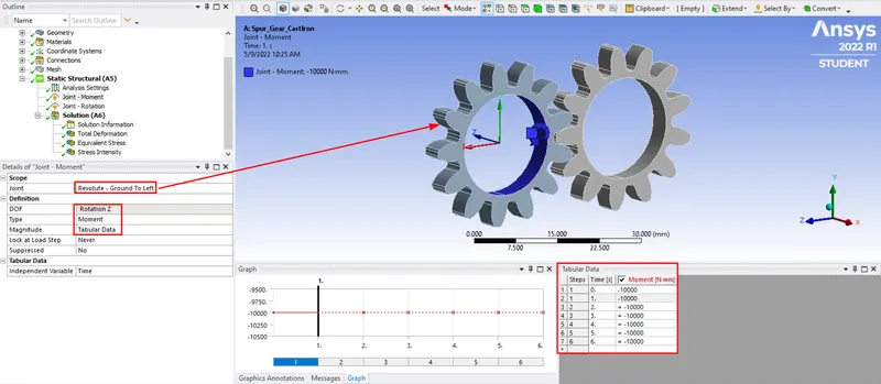
-10 (N-mm) value is specified for moment of left gear.
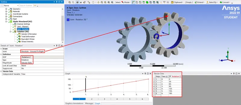
180 degree rotation is specified in 6 time steps for the right gear.
Requesting Outputs:-
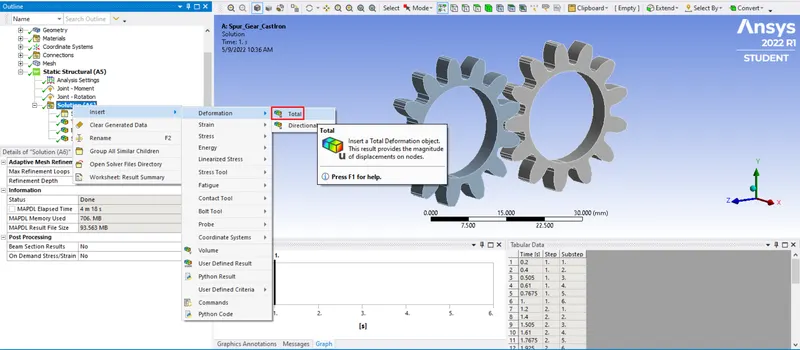
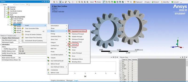
Here we have to request outputs for the VonMisses Stress, Stress Intensity, and for Total Deformation.
To request Output for Stress, Right Click on the Solution > Insert > Stress > Equivalent Von Misses Stress.
To request Output for Strain, Right Click on the Solution > Insert > Stress > Intensity.
To request Output for Total Deformation, Right Click on the Solution > Insert > Deformation > Total Deformation.
NOTE:- Same Procedure is followed for other two cases with Cast Steel and Cast Bronze Materials.
RESULTS:-
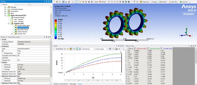
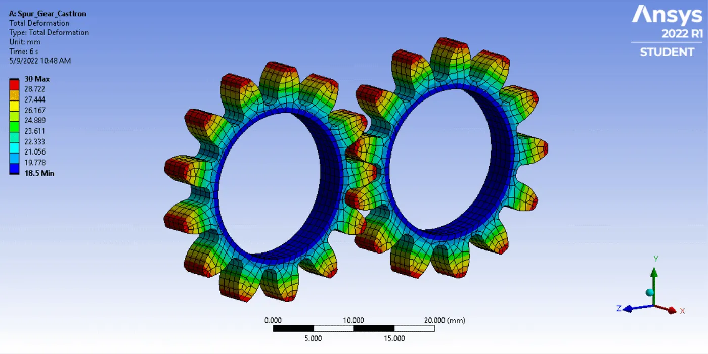
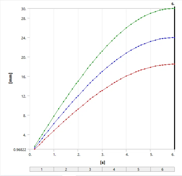
TOTAL DEFORMATION:-
Case-1 Cast Iron:-
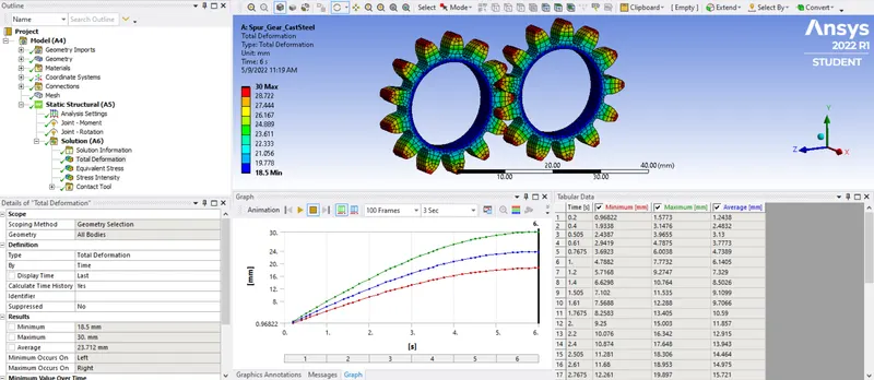
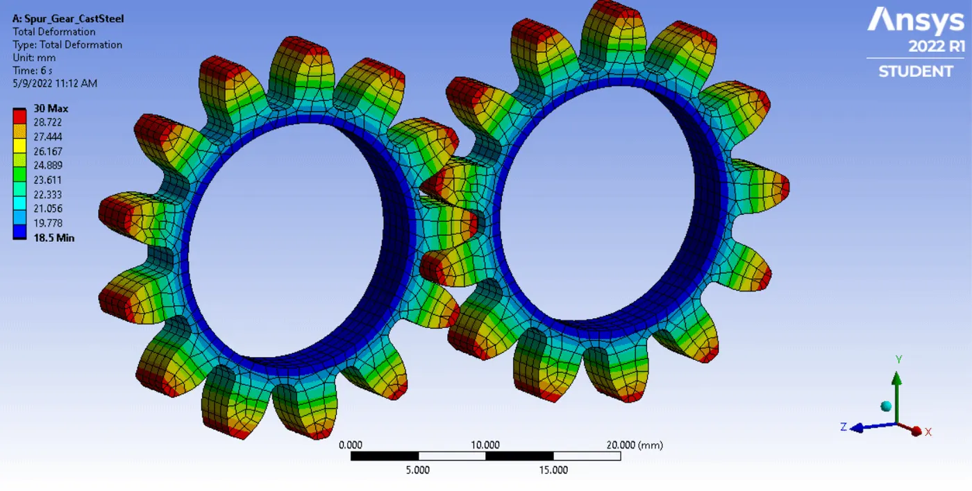
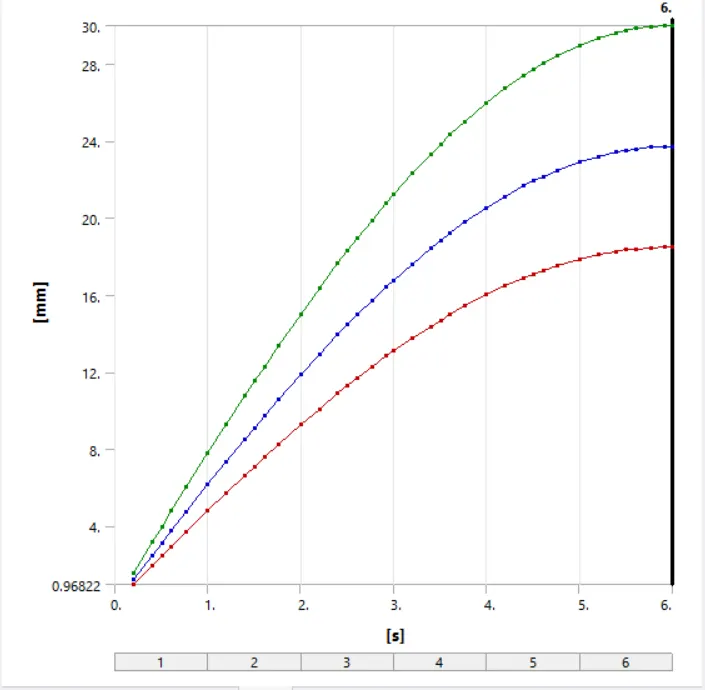
Case-2 Cast Steel:-
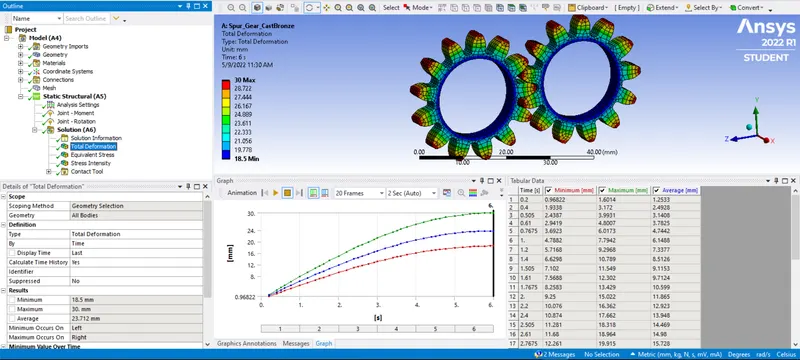
Case-3 Cast Bronze:-
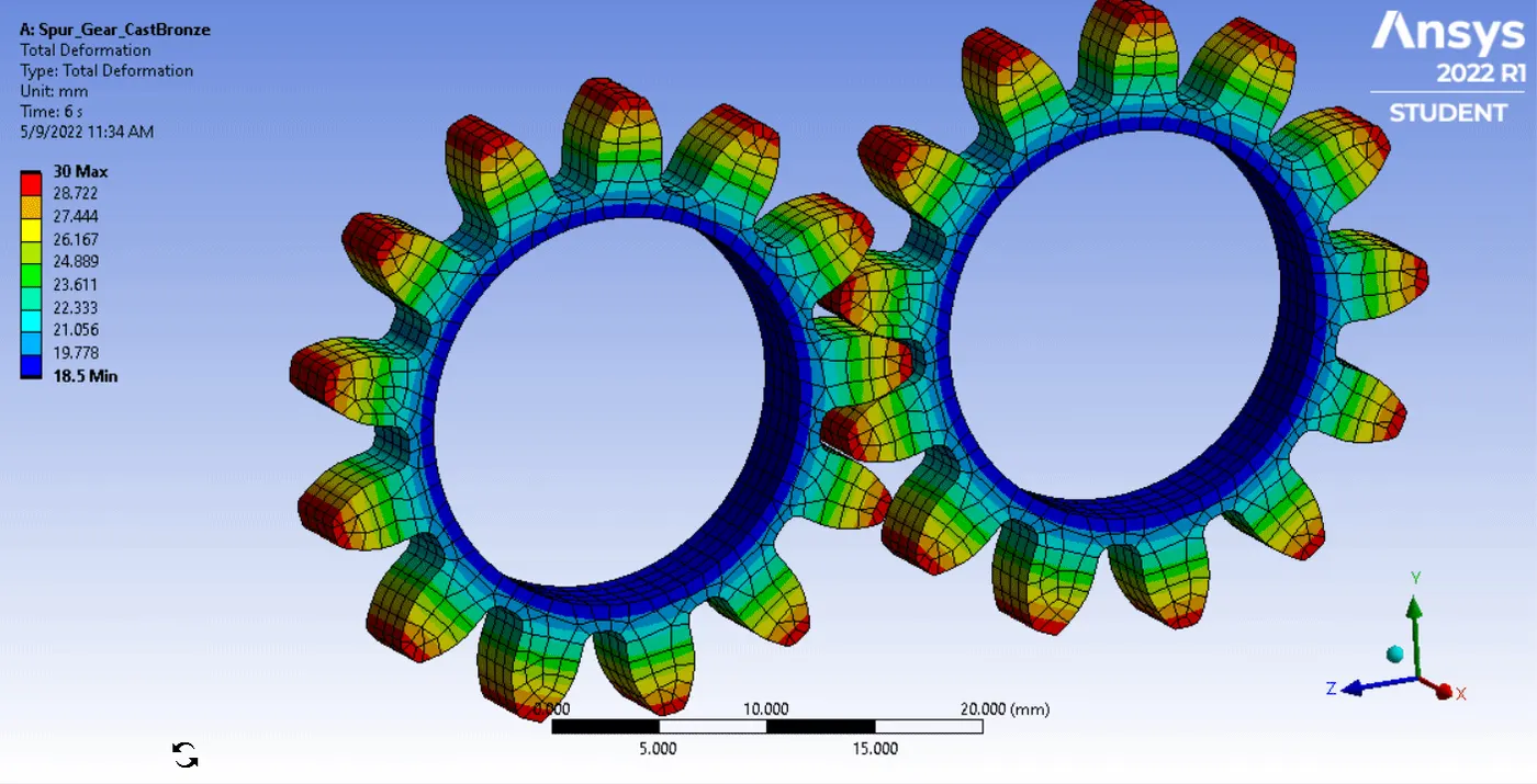
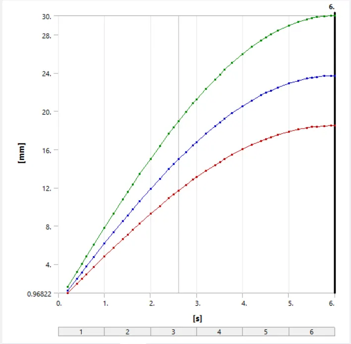
EQUIVALENT STRESS:-
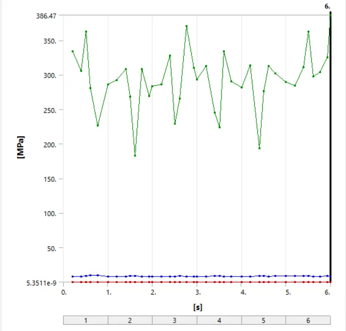
Case-1 Cast Iron:-
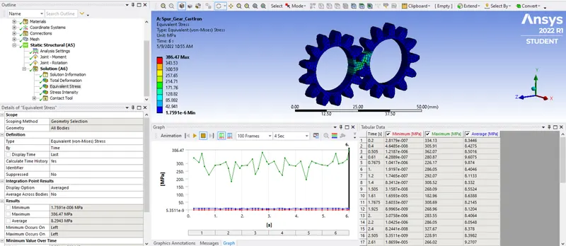
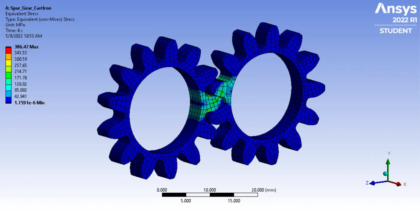
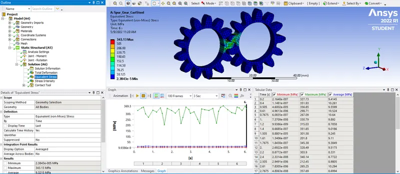
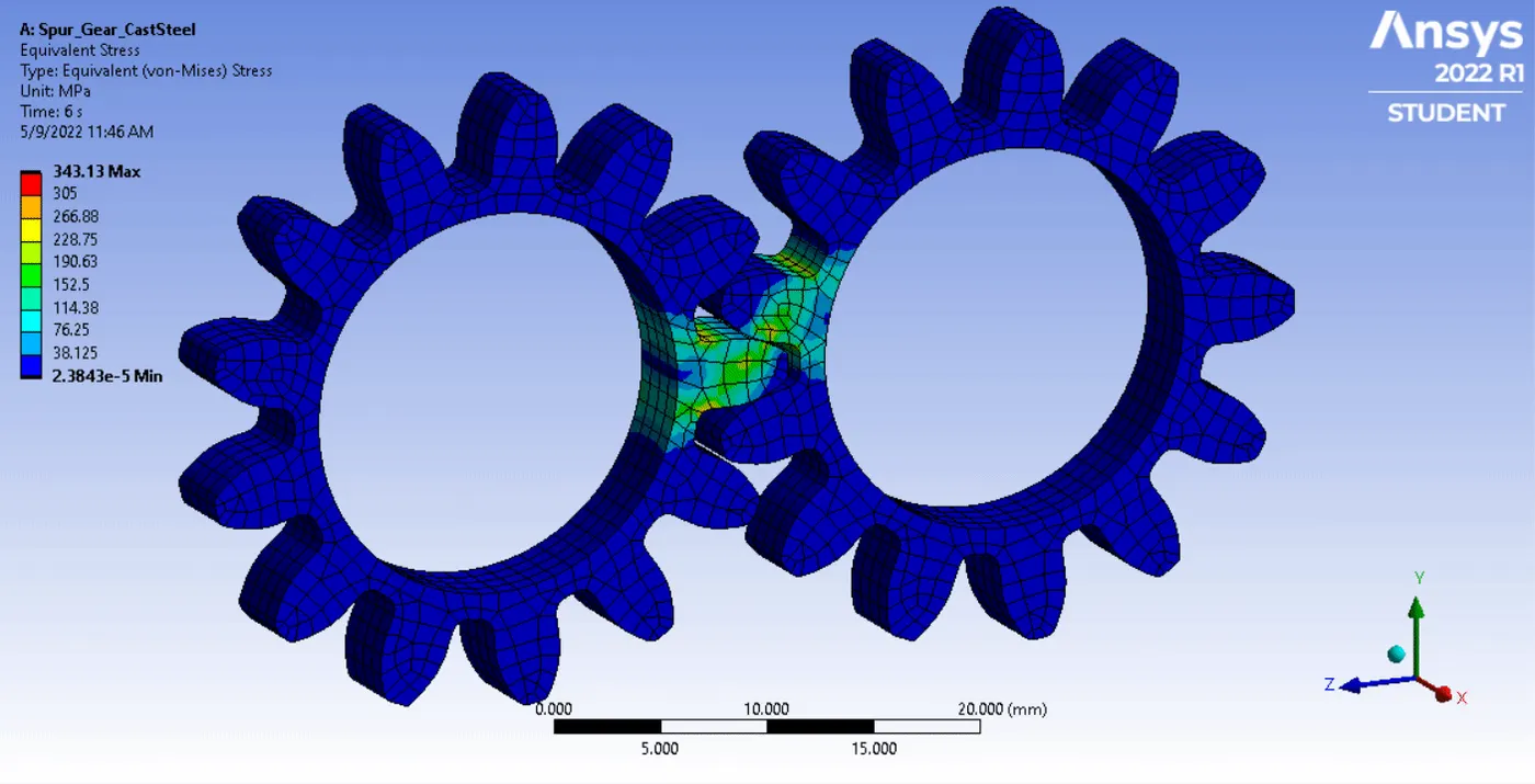
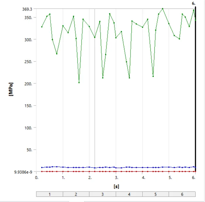
Case-2 Cast Steel:-
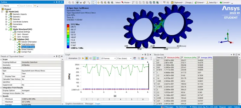
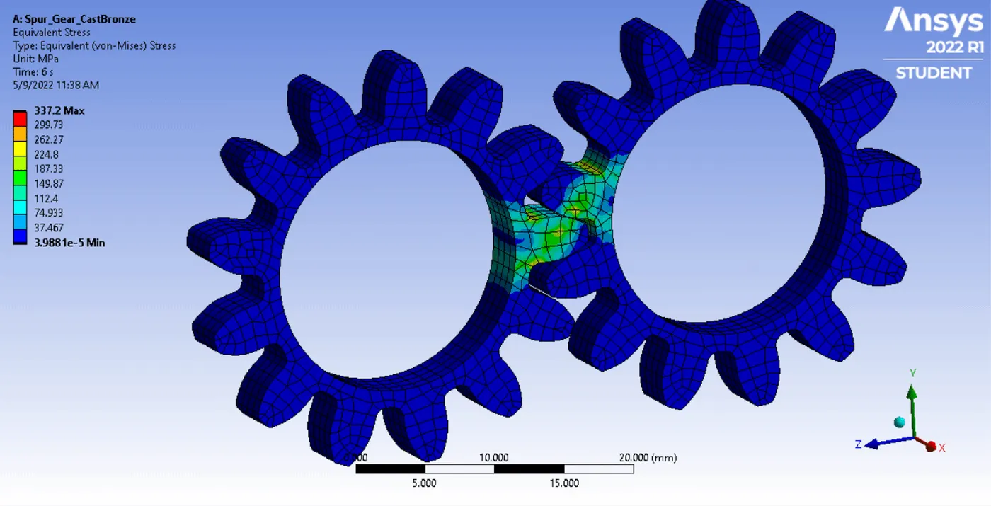
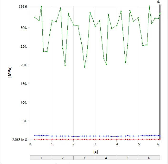
Case-3 Cast Bronze:-
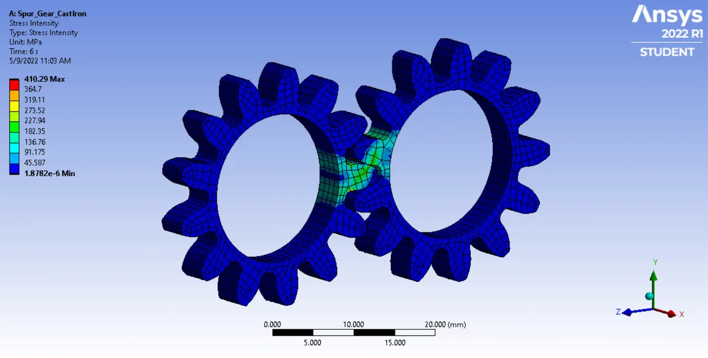
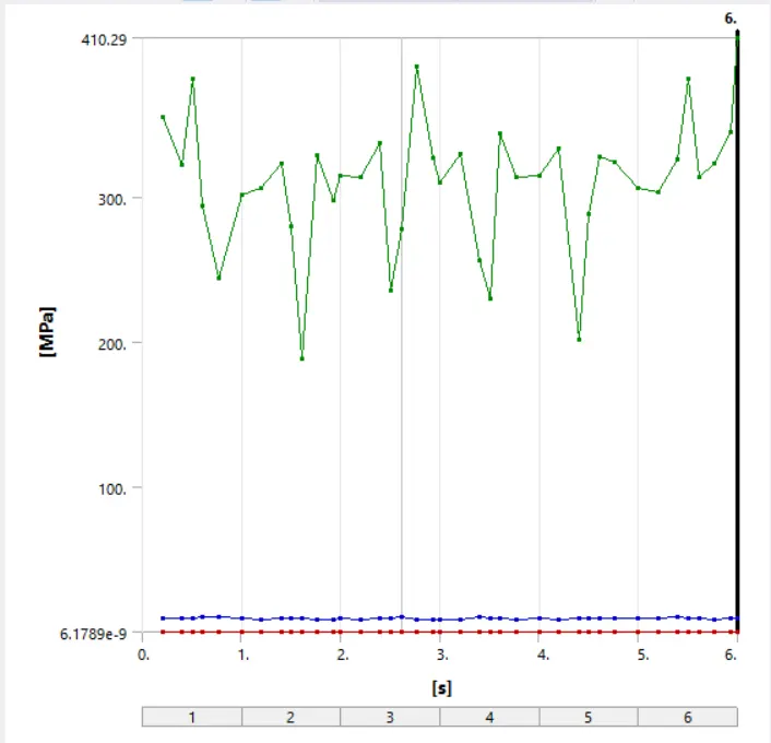
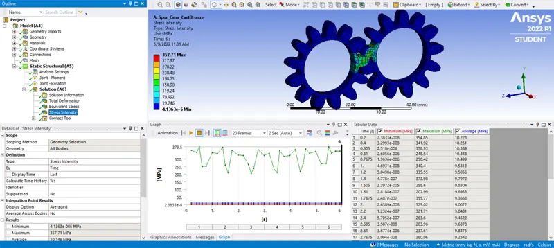
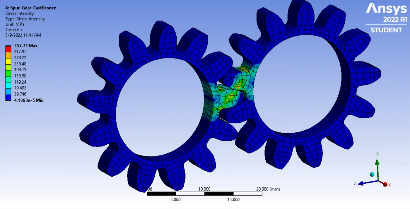
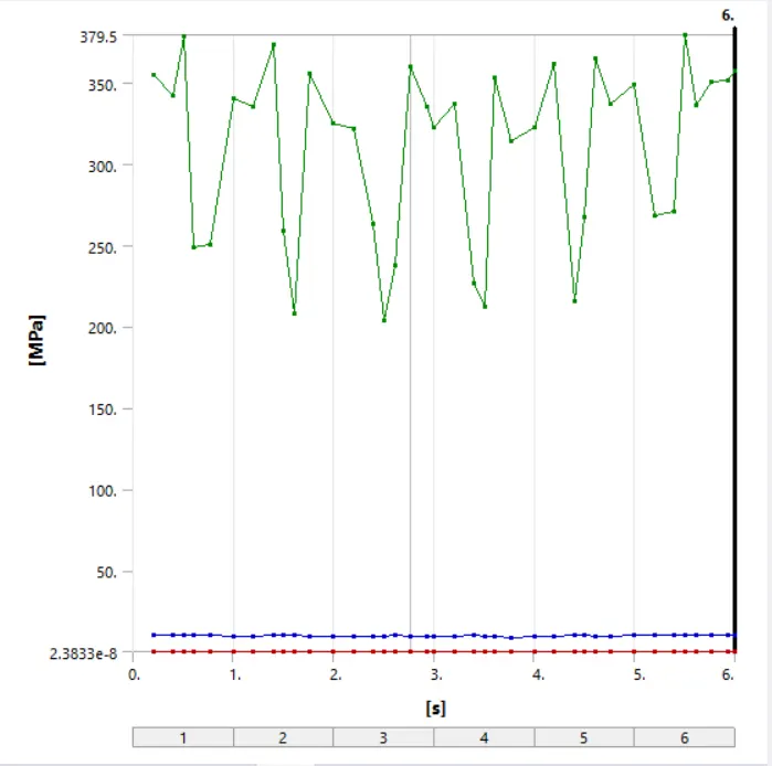
STRESS INTENSITY:-
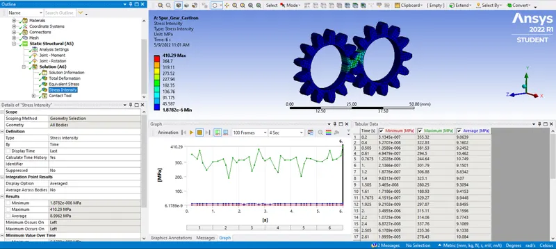
Case-1 Cast Iron:-
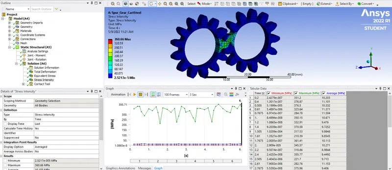
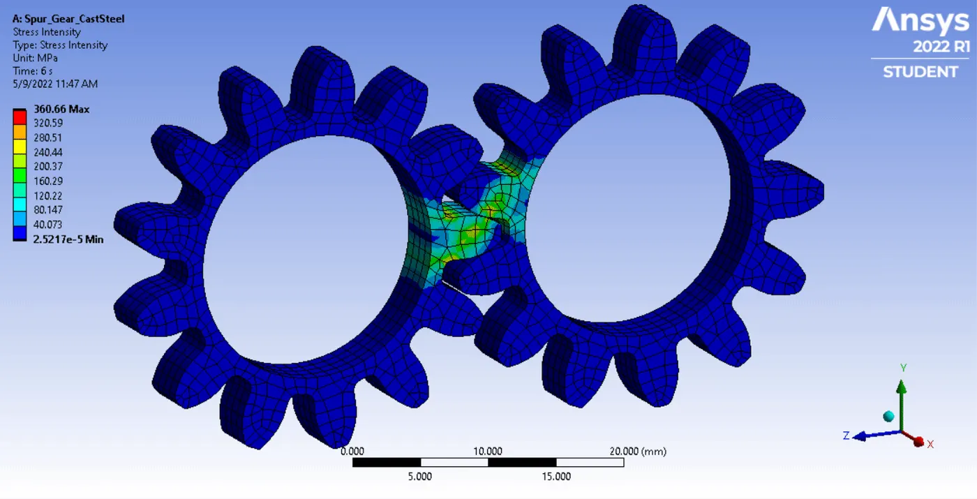
Case-2 Cast Steel:-
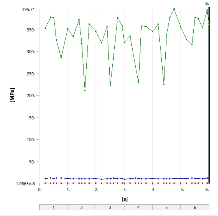
Case-3 Cast Bronze:-
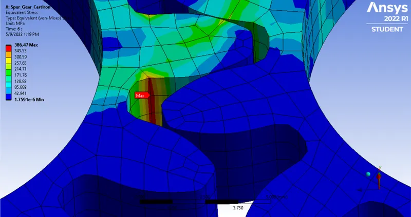
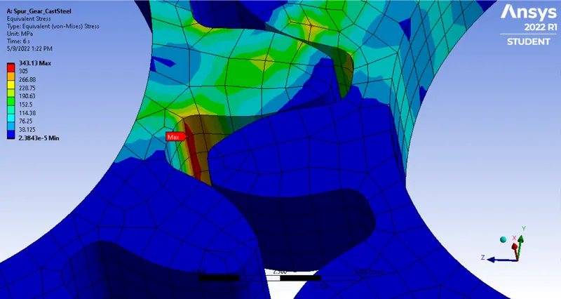
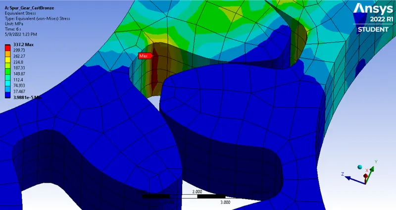
MAX. EQUIVALENT STRESS:-
Case-1 Cast Iron:-
Case-2 Cast Steel:-
Case-3 Cast Bronze:-
COMPARISION:-
| Case | Max. Equivalent Stress (Von Mises) | Max. Stress Intensity | Max. Total Deformation |
| (Mpa) | (Mpa) | (mm) | |
| CASE-1 | 386.47 | 410.29 | 30 |
| CASE-2 | 343.13 | 360.66 | 30 |
| CASE-3 | 337.2 | 357.71 | 30 |
CONCLUSION:-
We know that Yield Strength of a material is considered as design strength for the material which is obtained at lower yield point of the Stress-Strain diagram and if stress induced in the material exceeds this value, the material is considered to be failed. Tensile Yield Strength value taken for all the three materials are 344MPa, 349MPa and 144MPa for Cast Iron, Cast Steel and Cast Bronze respectively and the table clearly shows that in case-2 which is for Cast Steel material, the Max. Equivalent Stress(Von Mises Stress) is less than the Tensile Yield Strength of cast steel. Max. Equivalent Stress(Von Mises Stress) value for other two materials are more than the Tensile Yield Strength so Cast Steel is the material that will be suitable to chose in this case.