Week 1 Spur Gear Challenge
Analysis of spur gear for different materials
Objective:
To determine the most suitable material for the spur gear by performing the contact simulation.
The materials used in the simulation are Cast Iron, Cast Steel, and Cast Bronze.
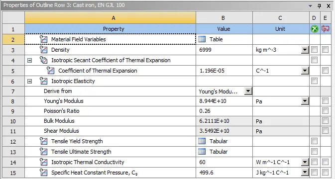
The material cards used are shown below
Cast Iron:
The used material can be found in Granta Design sample materials in the academic version of ANSYS.
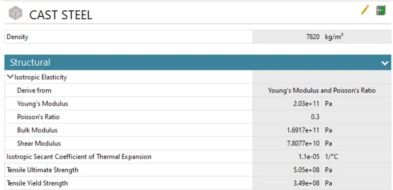
Cast steel:
The material is not found in the material library. New material with the properties mentioned below is created.
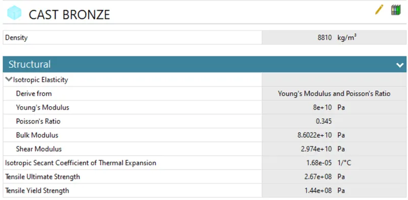
Cast bronze:
The material is not found in the material library. New material with the properties mentioned below is created.
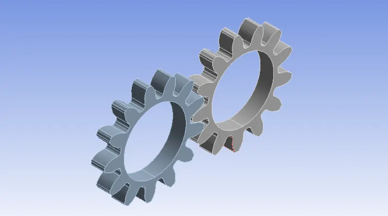
Import the given model:
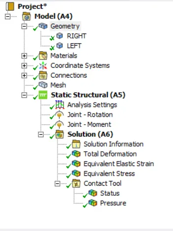
In the tree, we can see the operations performed on the given model to extract the results.
Under the geometry, we can see the parts in the GUI. We can rename, hide, and provide point mass.
Under the materials, we can see the active material cards which can be used in the current simulation.
Under the coordinate system, we can see the global coordinate system and if needed we can define the local coordinate system at a certain location.
Under the connections, In this case, as contact is taking place between 2 gears, we have to define the contact so that during the application of moment or rotation on the gears, the stress, strain, or any parameter at the contact can be defined. One has to provide constraints to cause the motion. Generally, a gear is attached to a bearing in turn to a shaft but in our case, only gear is provided so we need to create a joint between the inner body of the gear w.r.t ground.
In the mesh section, we can define the required target length and many other parameters.
In the Static Structural, In analysis settings, we can define the required number of steps a solution has to be calculated and will be discussed below. The motion to the joints is to be defined in this section.
In the Solution tree, one has to request the output property which is the outcome of the simulation.
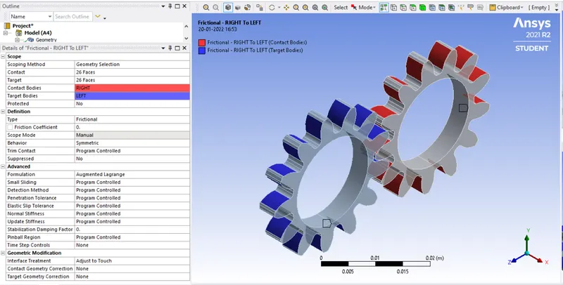
We can see the green and red faces on Gui, which are going to be in contact during the simulation.
To ease the process of simulation one can define symmetry if there. The type of contact is frictional which is defined. The formulation used in this case is Augmented Lagrange which enables the stiffness to the teeth of the gear in case of greater deformation to capture the deformation naturally. the Normal Lagrange formulation can handle large frictional sliding problems more effectively. The interface treatment is assigned as "adjust to touch".
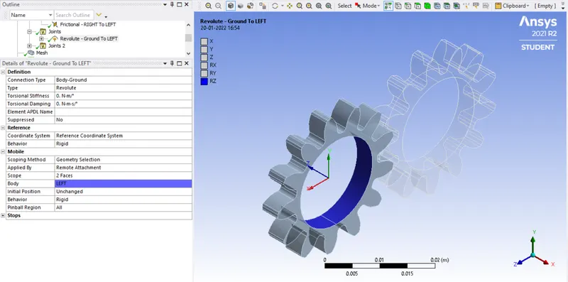
As we can see below, there is no bearing or a shaft to which the gear is connected. The inner faces of both gears are fixed to the ground by means of the revolute joint which enables the rotation to the gear by fixing the gear to the ground and the rotation is constrained in all directions other than Z.
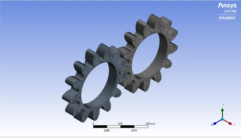
The finer mesh is generated to capture the geometry well. The finer mesh helps to locate the exact locations where the properties are maximum.
The mesh size used in this case is 5mm. The Adaptive sizing is disabled and in quality smoothening is set to low.
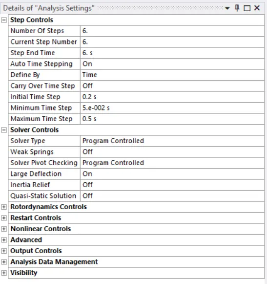
In static structural, Analysis settings are used to define the number of steps, in our case we have defined seven steps to calculate the solution. Auto time stepping is turned on and defined by time. The initial time step is provided as 0.2 s, minimum as 0.05 s, and maximum as 0.5s. The large deflection in the time step is turned on.
A number of time steps are based on the time up to which the analysis has to be done. For example, the time step is 5 milliseconds (0.005) and the number of steps is 2000. So you are doing the analysis for (0.005 x 2000=) 10 seconds.
In our case, auto time stepping is assigned. An important point to be made here is that automatic loading always works through the adjustment of the time step size; and that the loads that are applied are automatically adjusted if ramped boundary conditions are activated. In other words, the time step size is always subjected to possible adjustment when automatic loading is engaged. Applied loads and boundary conditions, however, will vary according to how they are applied and whether the boundary conditions are stepped or ramped. That is why this method may also be thought of as automatic loading.
Generally, we know a body is discretized into several elements and nodes. Let us consider a Quad element and its surrounding elements, Let us assume a force is acted on the node and deformation took place. so now that impact of deformation/stress/... has to be transferred to the adjacent node of the element. The time which it takes to do so is the time step. So if the timestep is very less the time taken for the simulation is quite less. If the geometry is complicated or the impact is severe causing much deformation, the time taken to transfer the information between the nodes is more which constitutes too much simulation time. So if the timestep is increased too much, instabilities occur in the simulation.
The major reason for providing finer mesh at sharp corners or at the fillet location is to capture the stress or deformation at that location more elements and nodes have to be defined which in turn increases the number of calculations
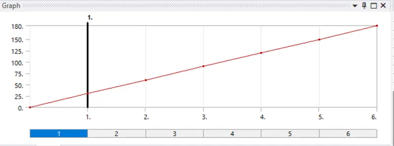
The rotation is provided on one gear and moment on the other.
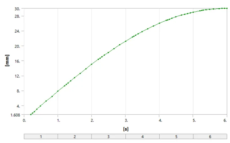
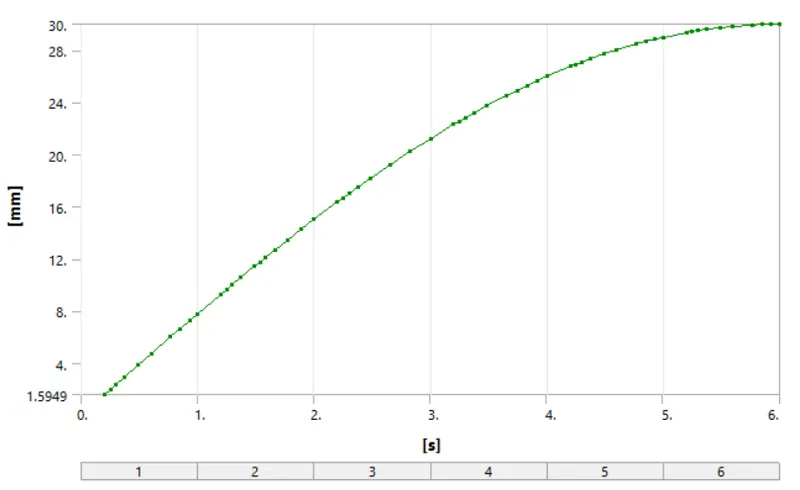
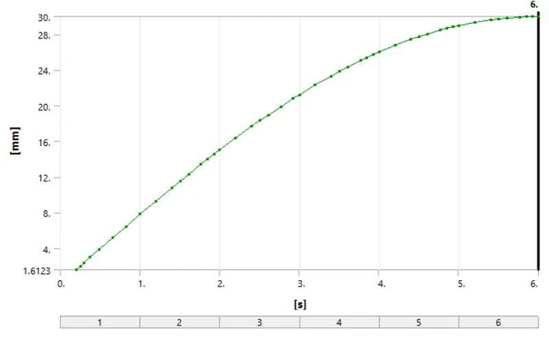
The below graph shows initially the rotation angle is zero degrees. During the first step, the angle provided is 30 degrees. Second step, 60 degrees,..., Sixth step, 180 degrees.
therefore, we have provided the total angle of 180 degrees to one gear to see how gear deformation, stress, and strain properties.
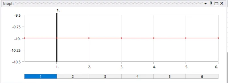
The constant moment of 10 N-m is applied in the opposite direction of the other gear rotation.
The output parameters are to be requested to generate the solution.
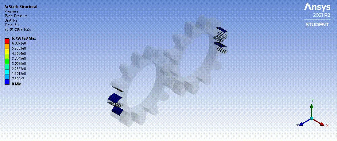
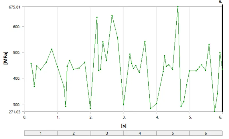
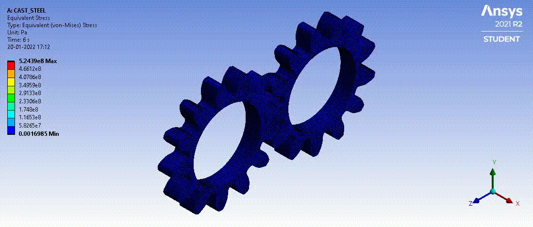
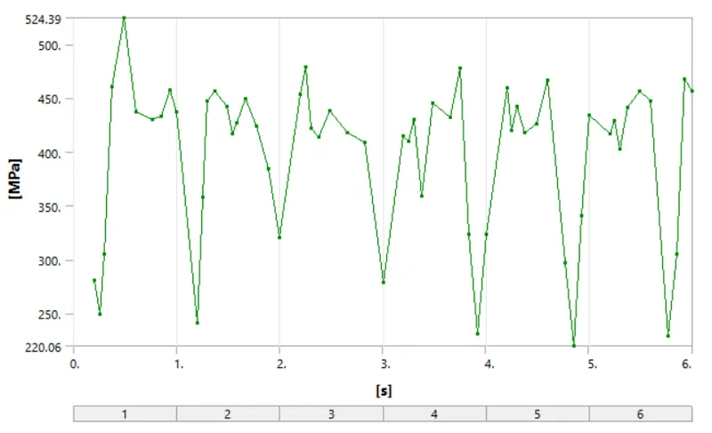
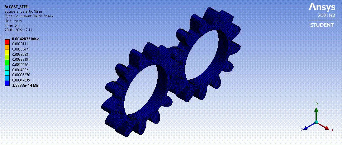
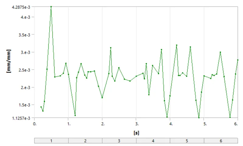
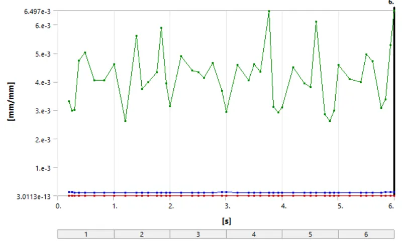
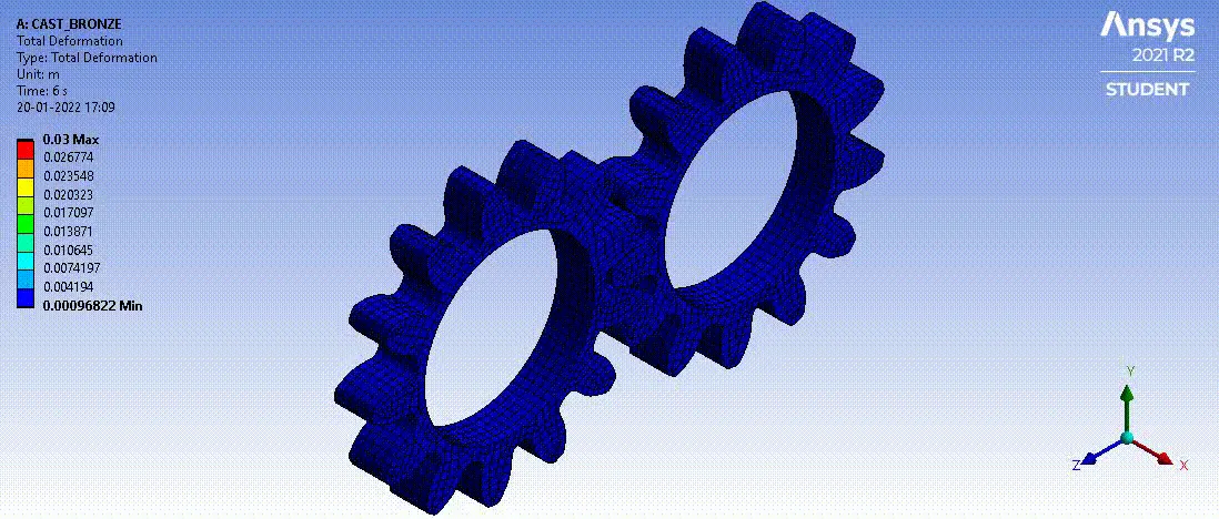
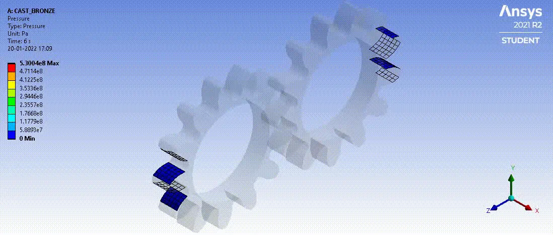
Total deformation, Von-Mises stress, Von-mises strain, and the contact pressure are requested.
Results:
Cast Iron
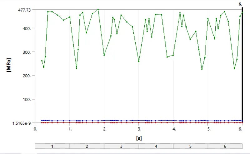
Von-Mises Stress:
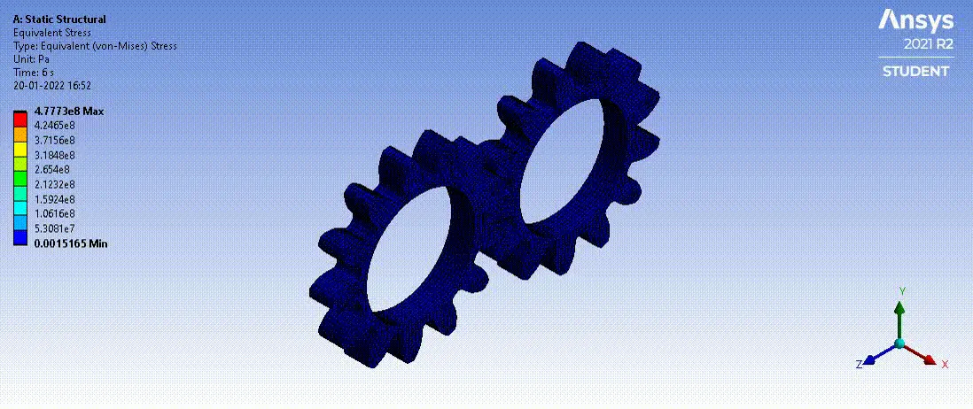
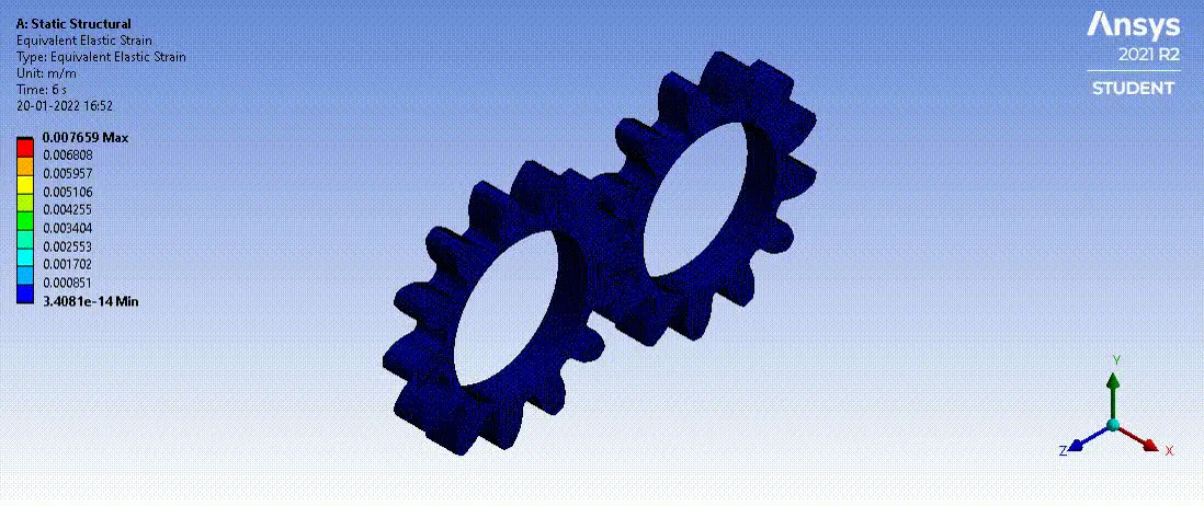
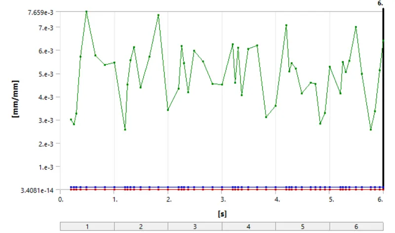
Von-Mises Strain:
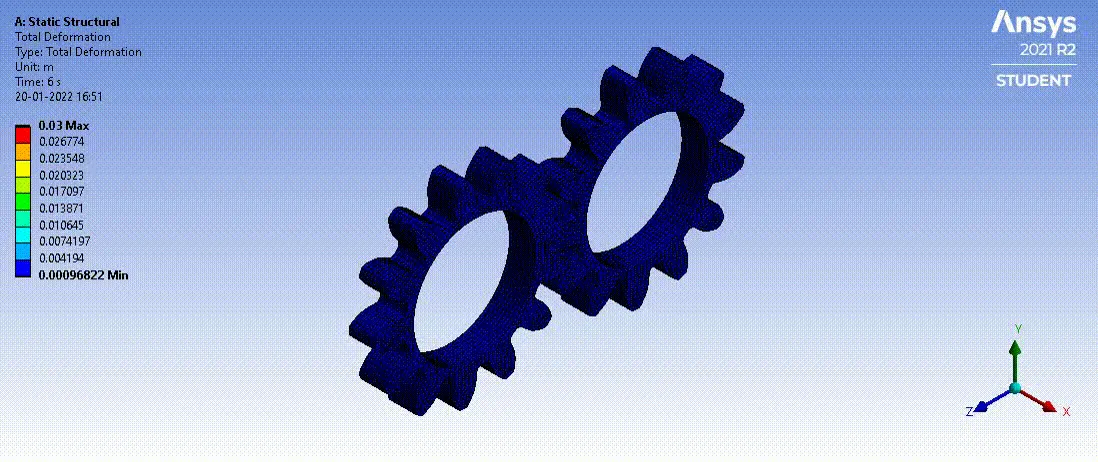
Total Deformation:
Pressure at the contact:
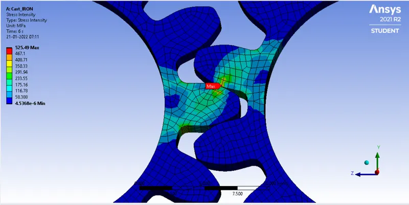
Stress Intensity:
Cast Steel
Von-Mises Stress:
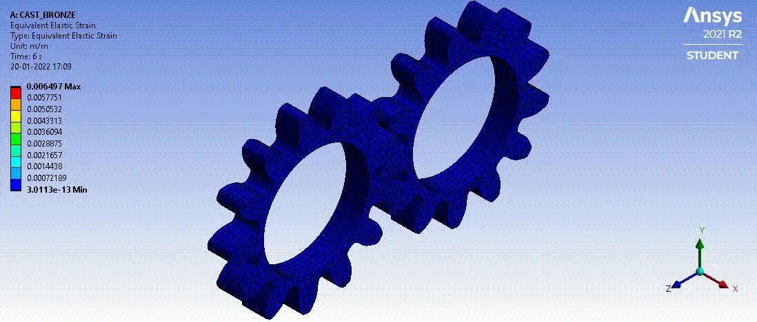
Von-Mises Strain:
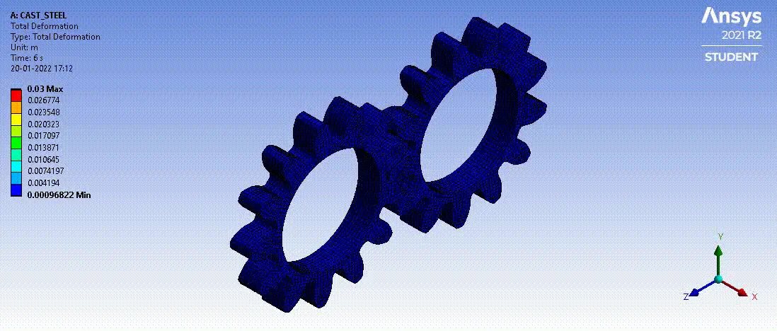
Total Deformation:
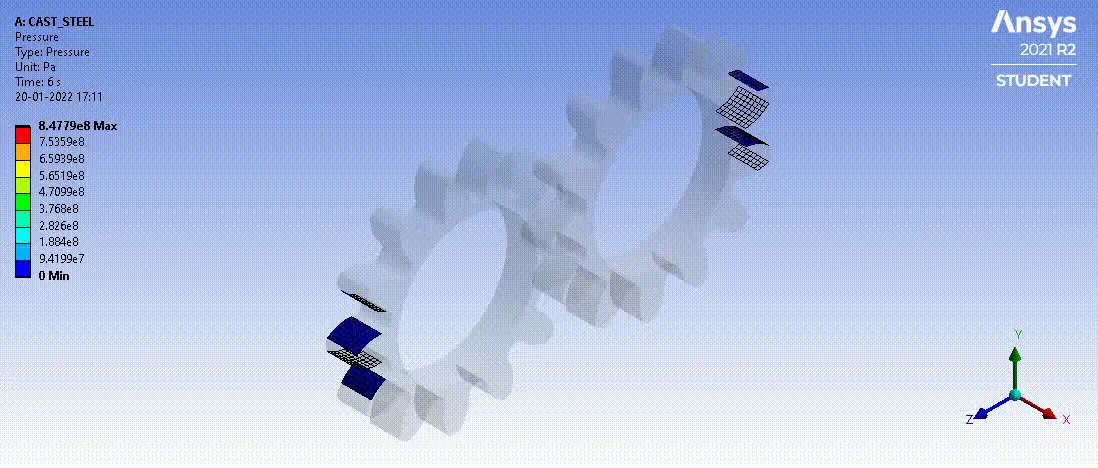
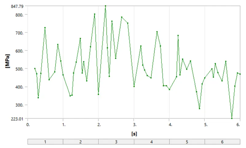
Pressure at the contact:
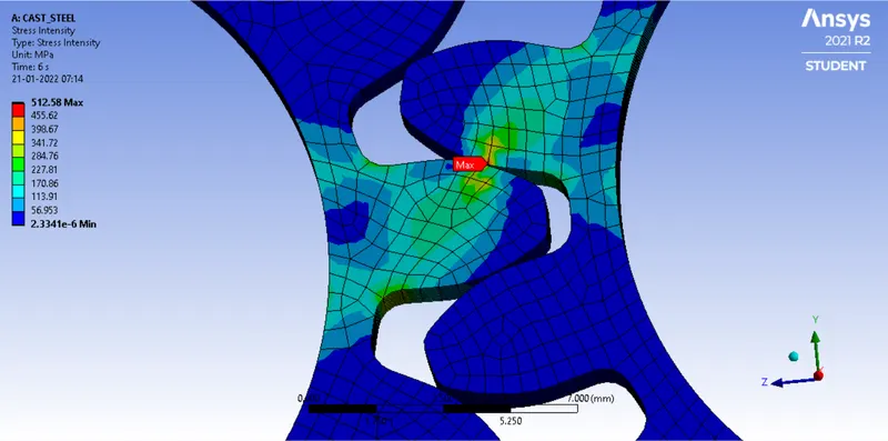
Stress Intensity:
Cast Bronze
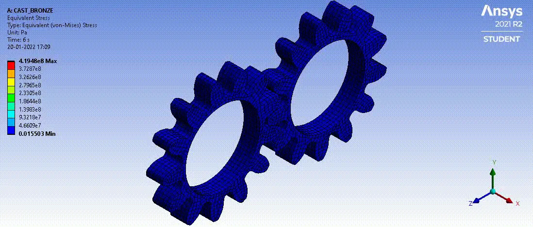
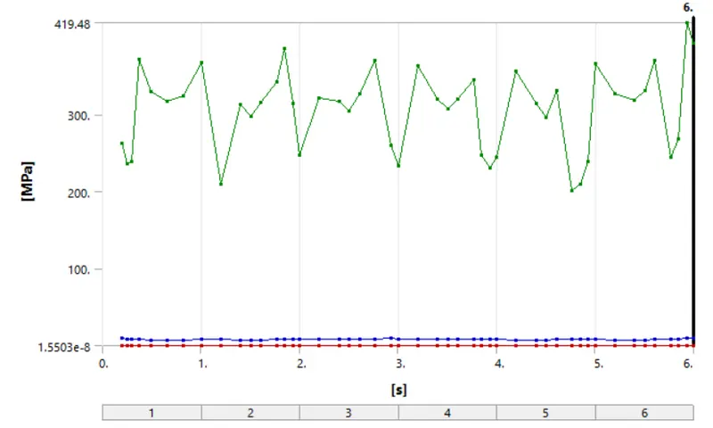
Von-Mises Stress:
Von-Mises Strain:
Total Deformation:
Pressure at the contact:
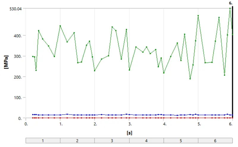
Stress Intensity:
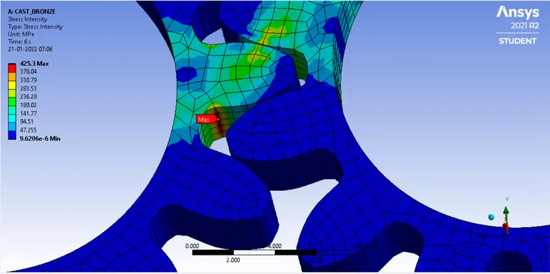
Comparison:

The stress intensity factor is a concept in Fracture Mechanics that is used to measure the stress concentration at a crack tip. In safety design, It is compared to a critical value and evaluates whether a component or structure is prone to fracture.
From the above-attached animations and images, we can see the stress intensity is high at the flank line for the cast iron and cast steel gears whereas stress intensity is high at the fillet region near the flank.
Conclusion:
The stress generated in cast iron gear is the highest followed by the cast iron and is least in the case of Cast bronze. The deformation in all three cases are same. During the contact, the pressure is lowest for the cast bronze gear. The stress intensity can also be seen as lowest for the cast bronze.
The property to be noticed is young's modulus. The deformation has remained constant for all materials but stress is seen varying. Hence, it is the young's modulus of the material that affects the stress developed in the gears.
We can conclude from the above results that the cast bronze would yield a longer life cycle as the stress intensity, stress, and the contact pressure are the lowest for cast bronze when compared.