Week 1 Spur Gear Challenge
Question: Static Structure Analysis of Spur Gears by using different materials
-------------------------------------------------------------------------------------------------------------------
INTRODUCTION:
Gears are toothed, mechanical transmission elements used to transmit motion and power in a variety of mechanical devices, such as clocks, instrumentation, and equipment and to reduce or increase speed and torque in a variety of motorized devices, including automobiles, motorcycles, and machines.
- Geared devices can change the speed, torque, and direction of a power source.
- Based on the design characteristics indicated above, there are several different types of gears Some of the more common types of gears employed throughout industry include:
- Spur gears
- Helical gears
- Bevel gears
- Worm gears
- Rack and pinion
Spur Gear:
The most common type of gears employed, Spur gears are constructed with straight teeth cut or inserted parallel to the gear’s shaft on a circular (i.e., cylindrical) gear body.
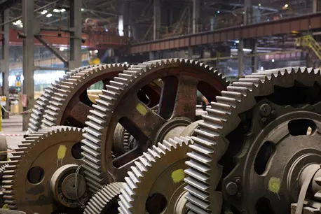
(Fig. Example of spur gears)
Fracture:
Generally two types of fracture were described.
- Ductile fracture/failure is the result of overload and exceeding the ultimate tensile strength of a material. Extensive plastic deformation is observed.
- Brittle fracture, catastrophic failure is observed, with little or no warning. No plastic deformation is observed. Tri-axial stress states, a stress concentration, or rapid loading are usually required for brittle fracture to occur.
Stress Intensity:
- Stress Intensity Factor (K) is used in the field of fracture mechanics. It predicts stress intensity near the tip of a crack caused by a remote load or residual stresses.
- The magnitude of K depends on:
- Sample geometry
- Size and location of the crack
- Magnitude of load
- Distribution of load on the material
- Stress Intensity Factor is measured by knowing the loading conditions and the crack size.
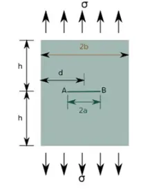
(Fig. Stress Intensity Factor (K))
Stress Intensity Factor (K) = uniform stress (`sigma`) * `root`(`pi`* a)
Where, a = length of the crack.
Assuming the crack as an ellipse, semi minor axis = 0, and thus consider only a.
-------------------------------------------------------------------------------------------------------------------
ANALYSIS:
CASE: 1 Material: Cast Iron (Ductile)
CASE: 2 Material: Cast Steel
CASE: 3 Material: Cast Bronze
Note: The analysis setup for CASE: 1 demonstrated.
CASE: 1 Material: Cast Iron (Ductile)
- Open Ansys Workbench (I have used Ansys Workbench version: 2021 R1 Student version)
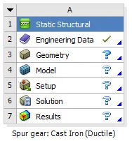
- Toolbox -> Analysis Systems -> Double click on the Static Structural
Project Schematic:
Engineering Data:
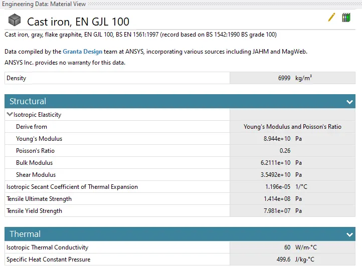
- Select the material “Cast Iron, EN GJL 100” from ANSYS GRANTA Materials Data with its all default properties.
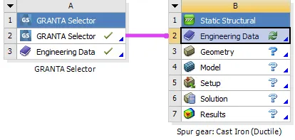
(Fig. Engineering Data)
Geometry:
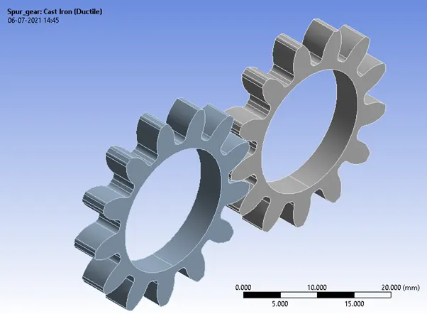
- Right click on Geometry -> Import Geometry -> Browse…folder -> Skill_Lync_Spur_Gear.stp
- The shared 3D model of Spur gear is imported into ANSYS Workbench for static structural analysis. This spur gear profile has 13 nos. of teeth with driving gear renamed as Right gear and driven gear renamed as Left gear.
(Fig. Geometry)
Model:
- Double click on Model and appear Ansys Mechanical Enterprise.
Material Properties (Cast Iron, EN GJL 100 2):
Connections Detail:
Contacts:
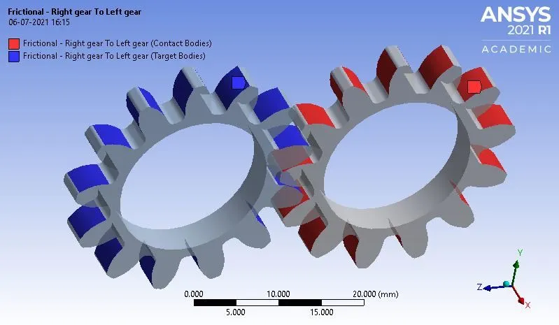
(Fig. Frictional contact of spur gear)
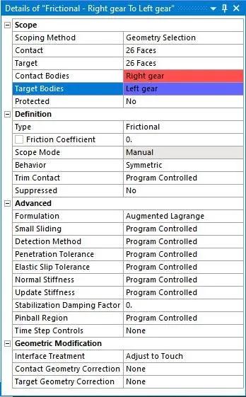
- For defining contacts between two gears, select the faces of the left gear as “Contact” and faces of the right gear as “Target” for the connection. There are 26 faces of each gear, must be selected.
- Type of the contact between the faces of Driving and Driven gear teeth is defined as Frictional contact with contact bodies being Right gear and Target bodies being Left gear.
- Behaviour - Symmetric
- Formulation - Augmented Lagrange is chosen to minimize the vibration and penetration, which Increases stiffness of gears.
- Interface treatment - Adjust to touch is chosen because if there is a gap between them or initial penetration, than this setting will help to adjust it and for any error can be avoided.
Joint Detail:
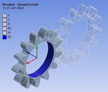
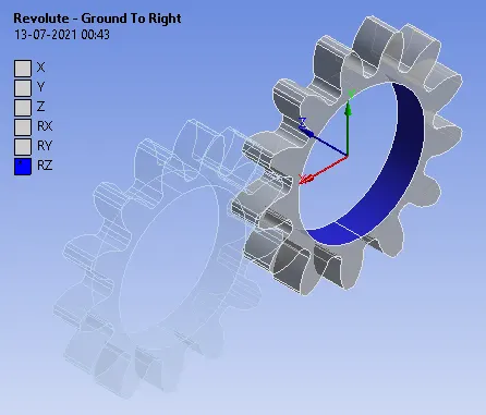
(Fig. Revolute Joint of spur gear)
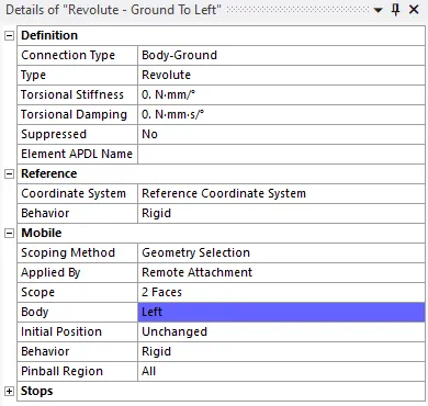
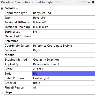
- Select the inner face (Internal diameter) of each gear.
- Connection Type - Body-Ground
- Type - Revolute
- We can see that in revolute joint, Degree of freedom for the gears automatically set to its axis or in Rz direction.
Mesh:
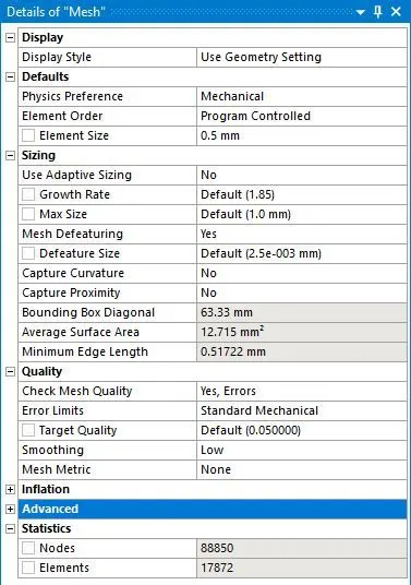
- The academic version of the software has the nodes and elements size limit are 128k.
- Element size - 0.5mm
- From the mesh statistics of the model, the number of nodes and elements generated are 88850 and 17872.
- Most of the elements are automatically taken as Hexahedral..
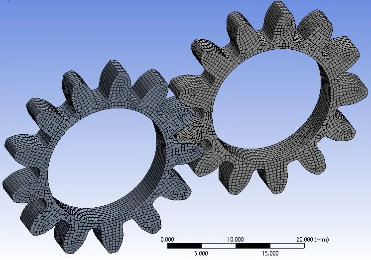
(Fig. Mesh of spur gear)
Boundary Conditions:
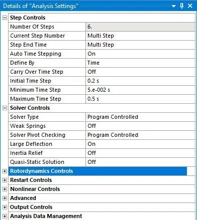
- Number of steps – 6
- Auto time stepping - On
- Defined by - Time
- The Initial, minimum and maximum time step is specified as 2s, 5e-2s and 0.5s respectively.
- In the solver controls, the large Deflection - set to “On”
Joint loads details:
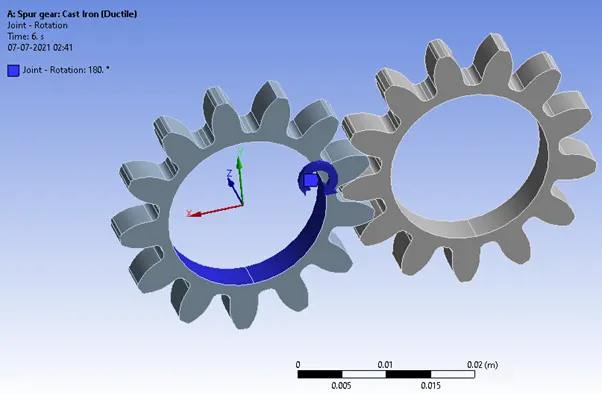
(Fig. Joint load - Left gear)
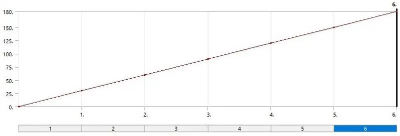
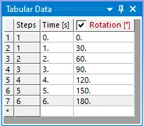
- Joint – Ground to Left
- Type – Rotation
- Magnitude – Tabular Data
- The left gear is driven gear hence; rotation (clockwise) for 180° is specified with an incremental value of 30° for each step.
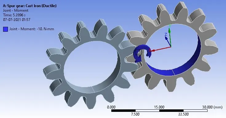
- Joint – Ground to Right
- Type – Moment
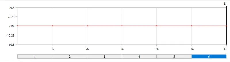
- Magnitude – Tabular Data
- The right gear is driving gear hence; moment (anticlockwise) of -10 N.m is specified for the entire steps.
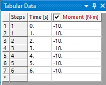
Note: Before changing the value of Moment (N.m), First of all, change the Unit conversion system (M, Kg, N, s, V, A)
-------------------------------------------------------------------------------------------------------------------
RESULTS AND DISCUSSIONS:
- Results for all the cases as given below:
| RESULT: (CASE-1) |
Material: Cast Iron (Ductile) |
Material Properties (Cast Iron, Ductile):
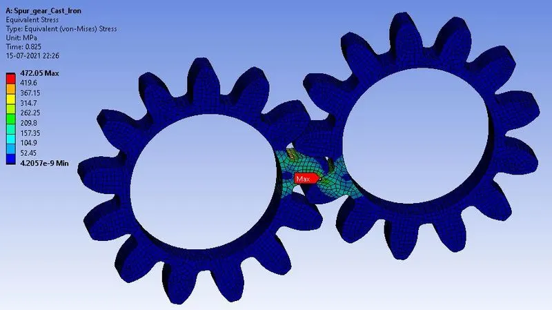
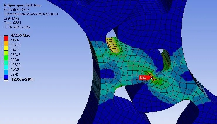
Stress Contours:
Stress Plot:
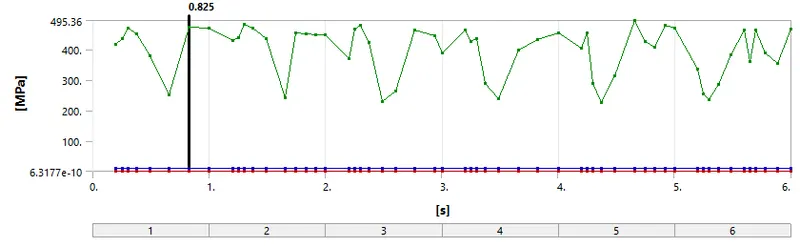
Detailed max. Stress Values:
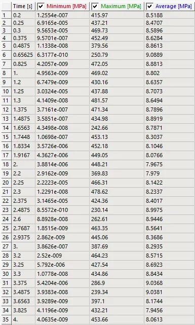
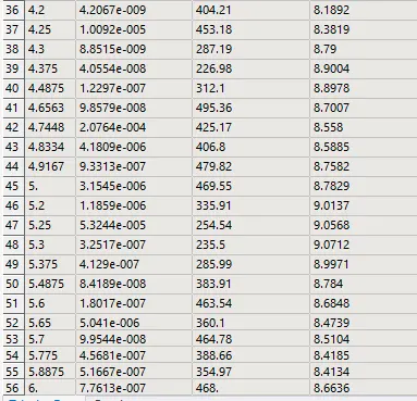
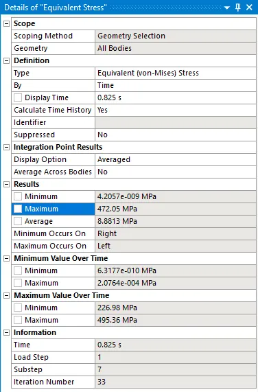
- From the tabular data, we can perceive that the maximum stress in gears is 472.05 MPa.
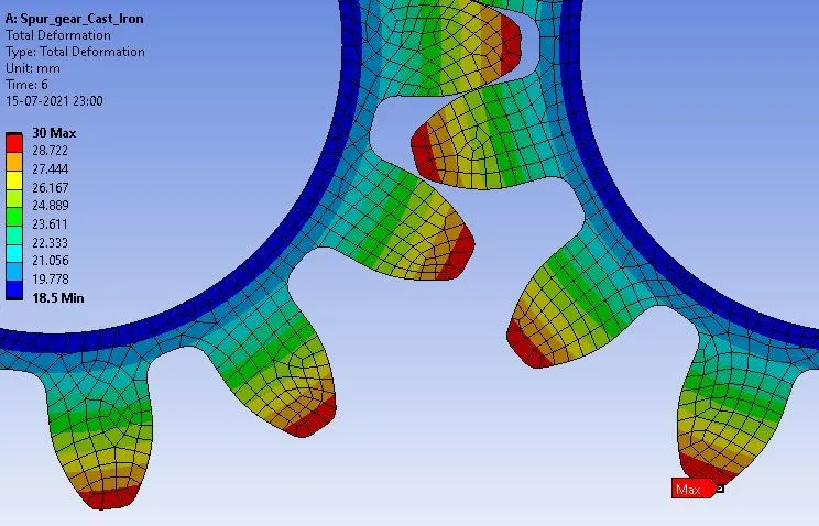
Total Deformation Contours:
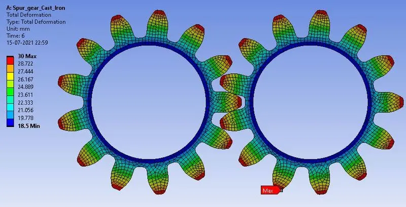
Total Deformation Plot:
Detailed Total Deformation Values:
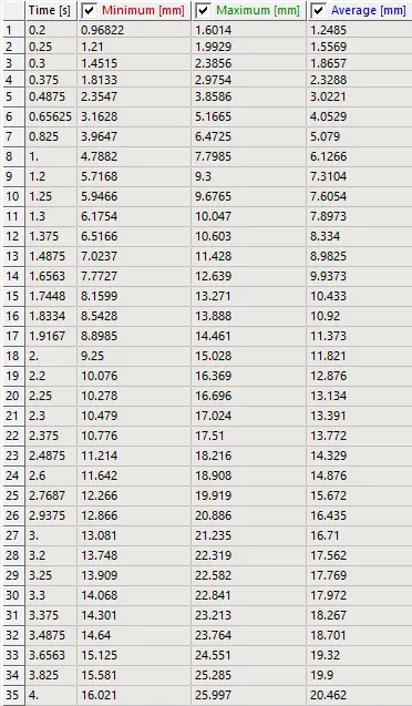
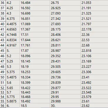
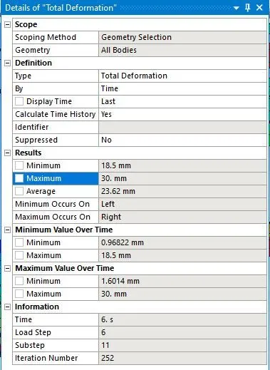
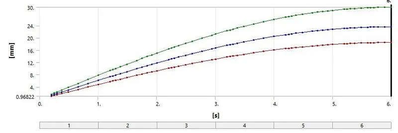
- From the tabular data, we can perceive that the maximum detailed deformation in gears is 30 mm.
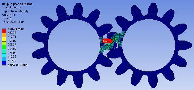
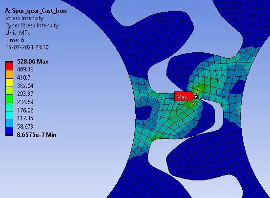
Stress Intensity Contours:
Stress Intensity Plots:
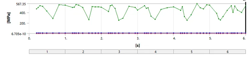
Detailed Stress Intensity Values:
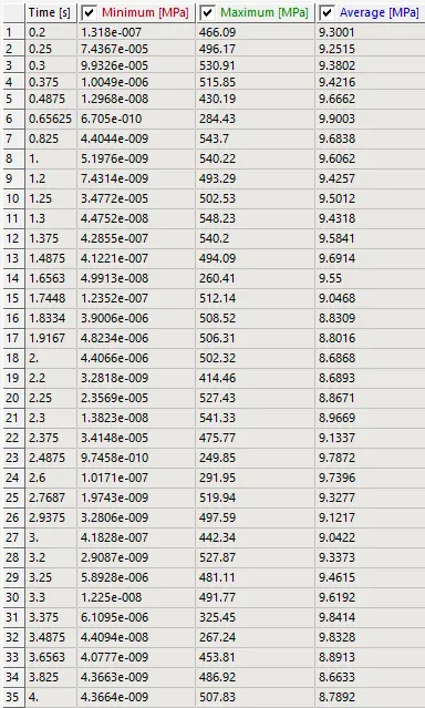
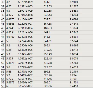
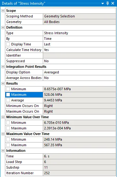
- From the tabular data, we can perceive that the maximum Stress Intensity in gears is 528.06 MPa.
Contact Status Contours:
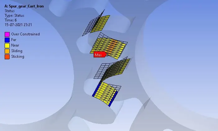
- We can observed that the Orange portion, which represents sliding at contact portion of gears.
- Also we can see that yellow and blue colours represents near and far areas.
- Sticking is happening here.
- Also we can see that there is no over constrained area in gear contacts.
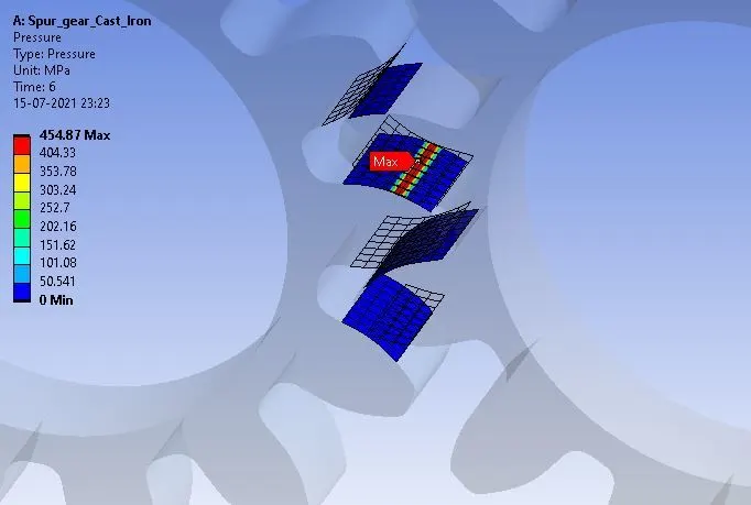
Contact Pressure Contours:
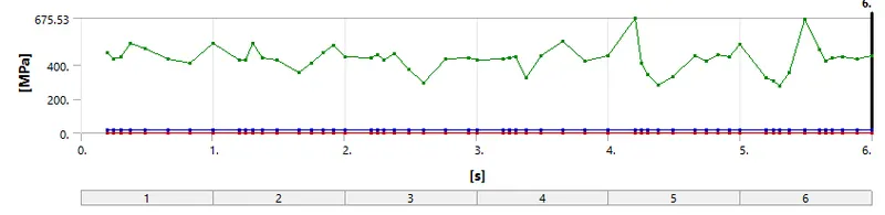
Contact Pressure Plots:
Detailed Contact Pressure Values:
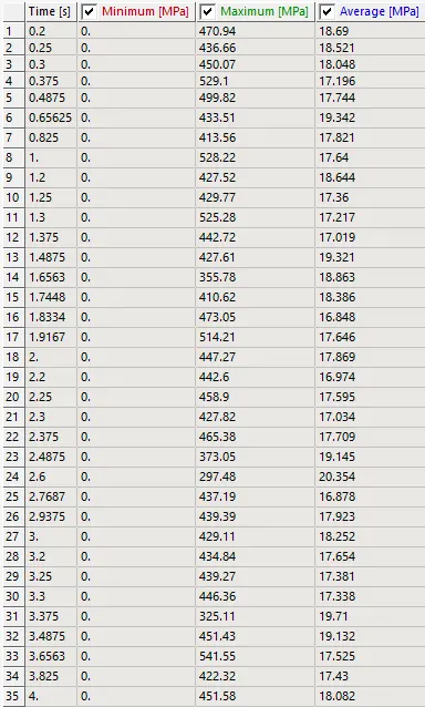
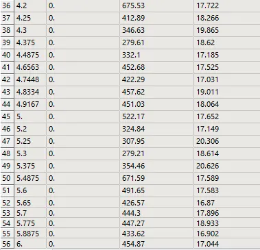
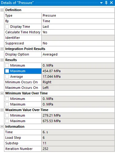
- From the tabular data, we can perceive that the Highest Pressure Generation is 454.87 MPa.
-------------------------------------------------------------------------------------------------------------------
| RESULT: (CASE-2) |
Material: Cast Steel |
Material Properties (Cast Steel):

Stress Contours:
Stress Plot:
Detailed Stress Values:
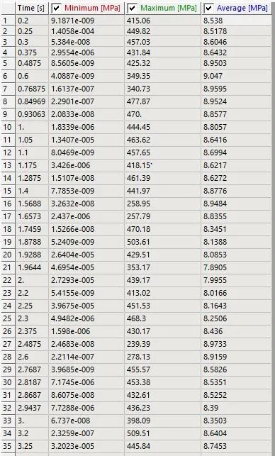
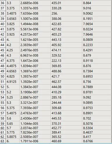
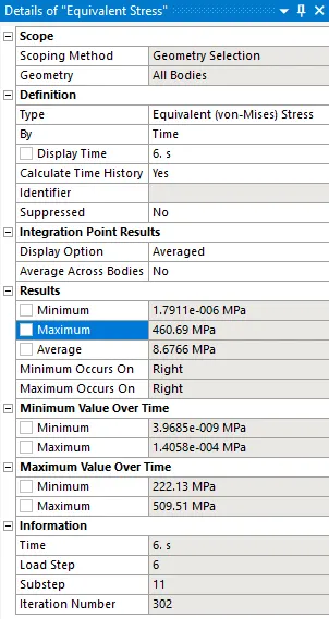
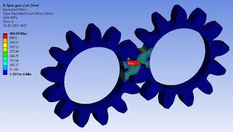
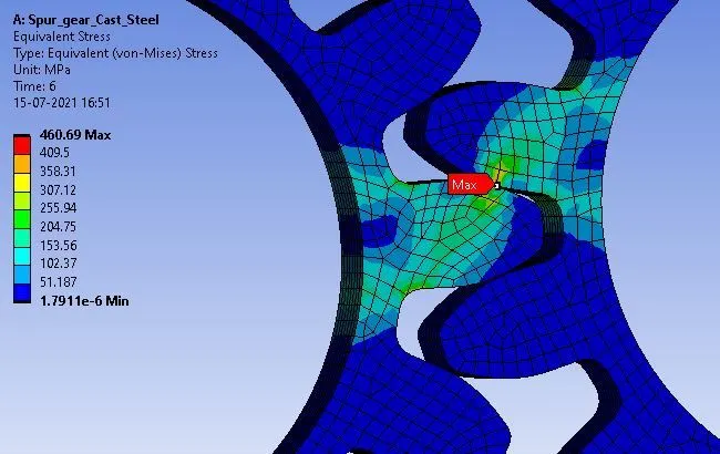
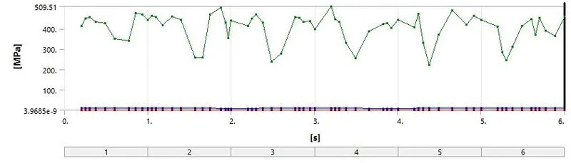
- From the tabular data, we can perceive that the Maximum stress in gears is 460.69 MPa.
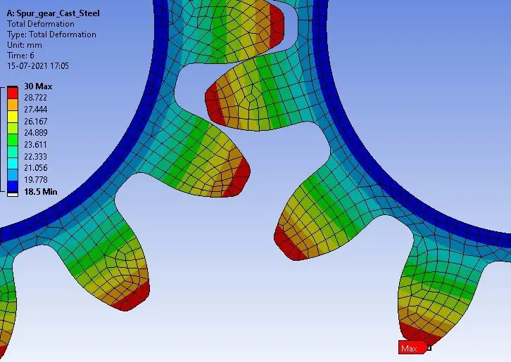
Total Deformation Contours:
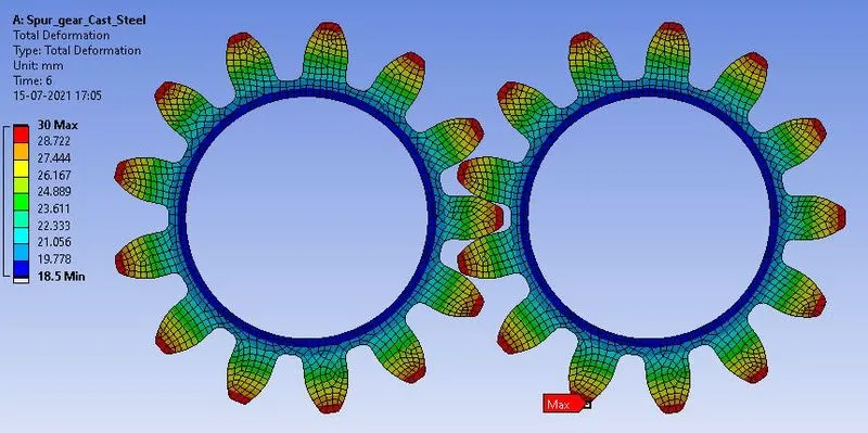
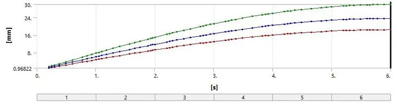
Total Deformation Plot:
Detailed Total Deformation Values:
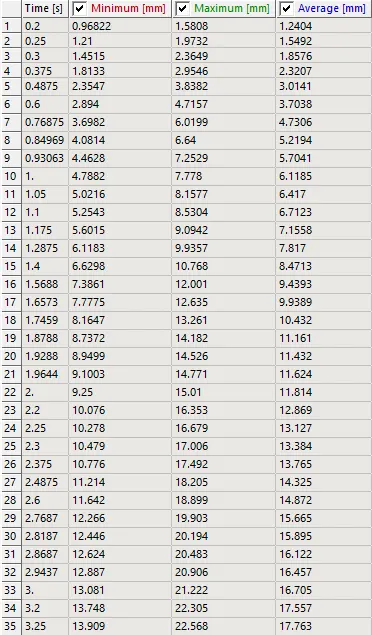
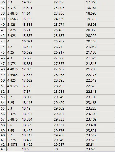
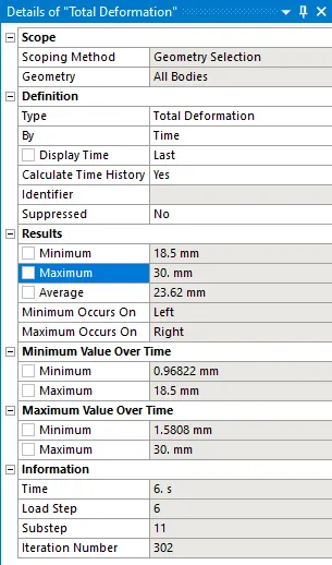
- From the tabular data, we can perceive that the maximum detailed deformation in gears is 30 mm.
Stress Intensity Contours:
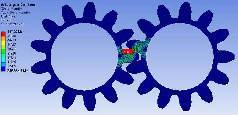
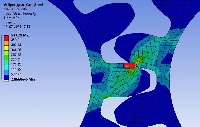
- From the Contour data, we can get that the Maximum Stress Intensity is 517.29 MPa. Beyond this limit, the crack propagation starts.
Stress Intensity Plot:
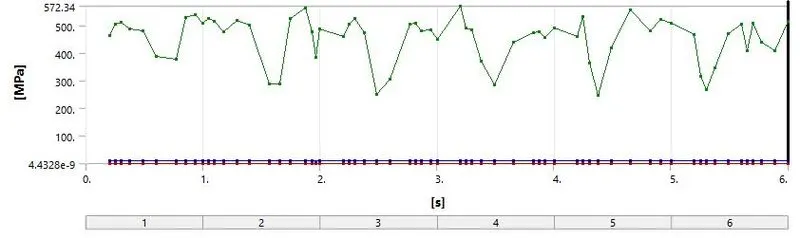
Detailed Stress Intensity Values:
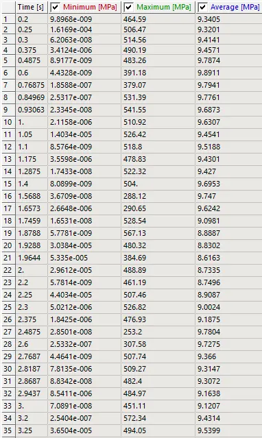
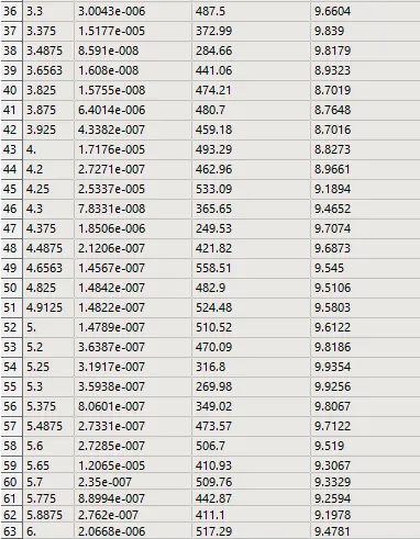
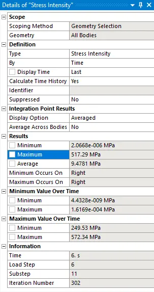
- From the tabular data, we can perceive that the maximum Stress Intensity in gears is 517.29 MPa.
Contact Status Contours:
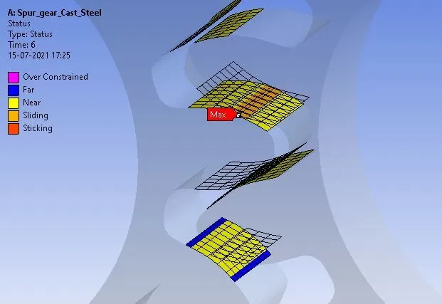
- We can observed that the Orange portion, which represents sliding at contact portion of gears.
- Also we can see that yellow and blue colours represents near and far areas.
- Sticking is happening here.
- Also we can see that there is no over constrained area in gear contacts.
Contact Pressure Contours:
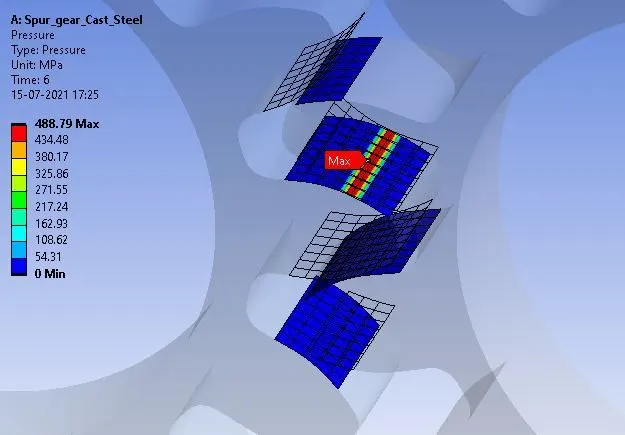
Contact Pressure Plot:
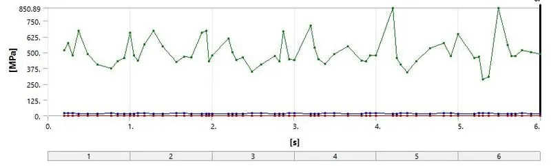
Detailed Contact Pressure Values:
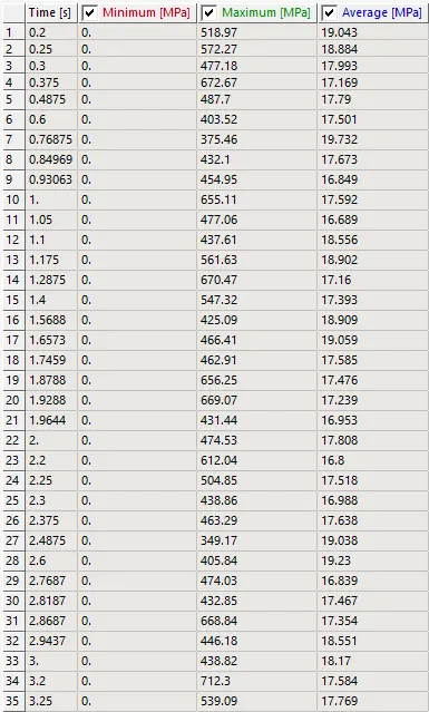
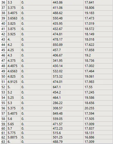
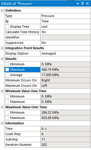
- From the tabular data, we can perceive that the Highest Pressure Generation is 488.79 MPa at 6 sec contact faces.
-------------------------------------------------------------------------------------------------------------------
| RESULT: (CASE-3) |
Material: Bronze, Cast |
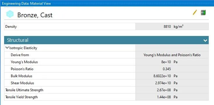
Material Properties (Bronze, Cast):
Stress Contours:
Stress Plots:
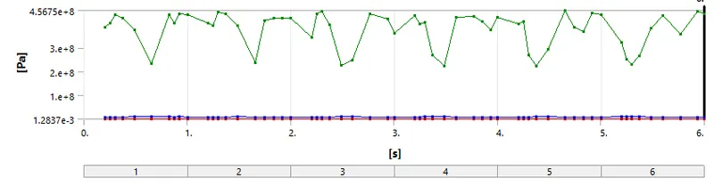
Detailed Stress Values:
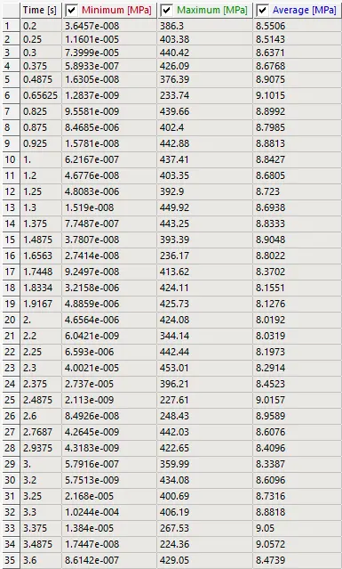
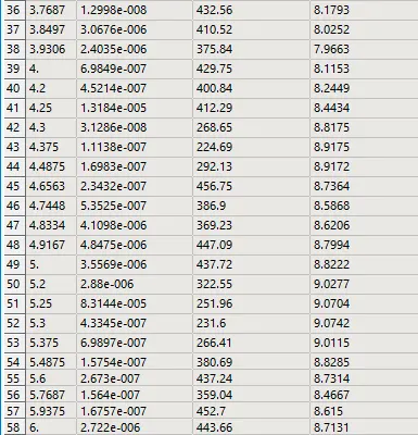
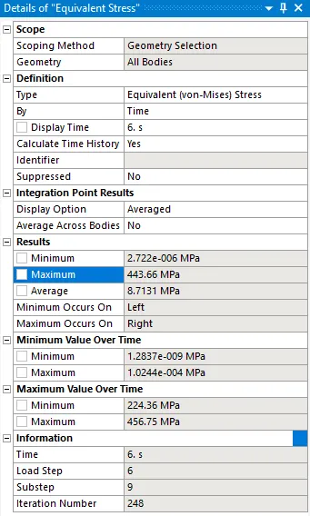
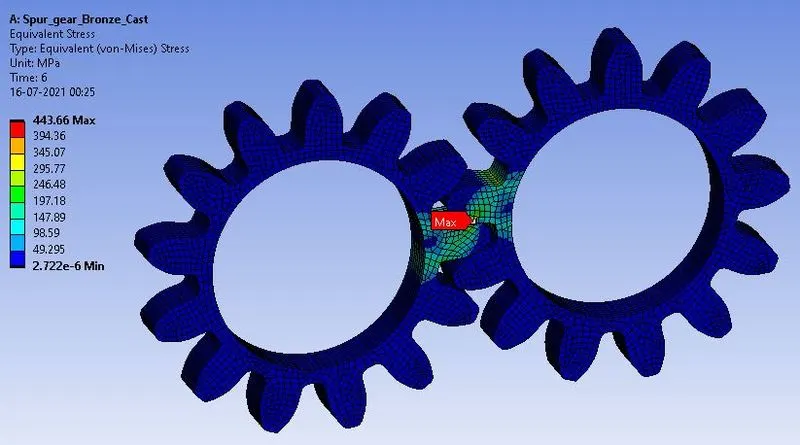
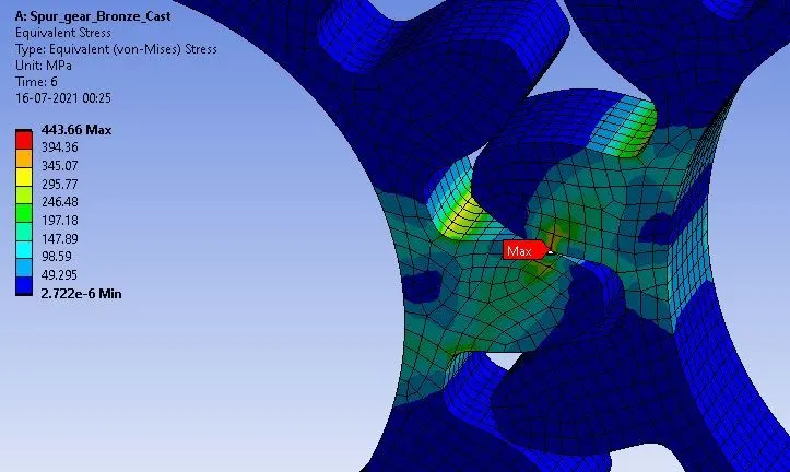
- From the tabular data, we can perceive that the Maximum stress in gears is 443.66 MPa.
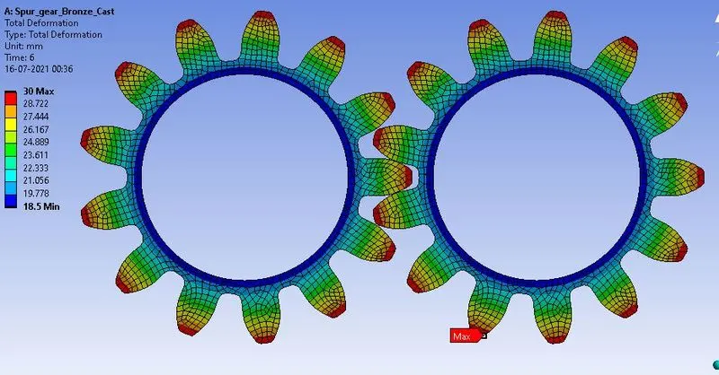
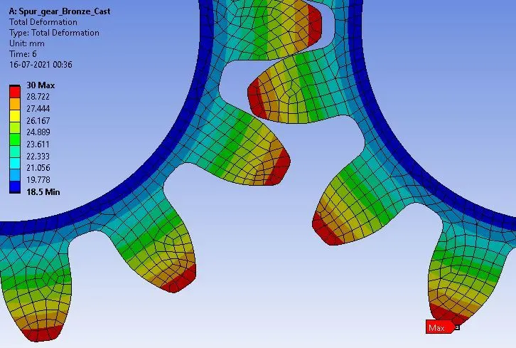
Total Deformation Contours:
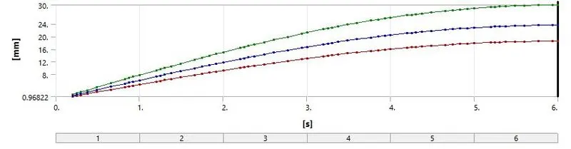
Total Deformation Plots:
Detailed Total Deformation Values:

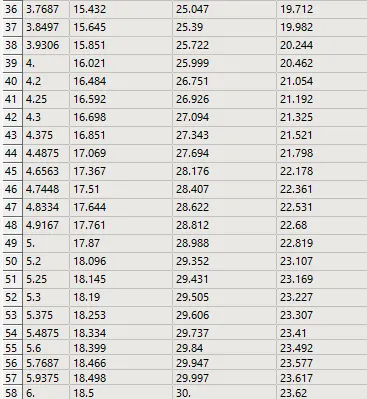
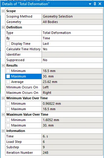
- From the tabular data, we can perceive that the Maximum Total Deformation in gears is 30mm.
Stress Intensity Contours:
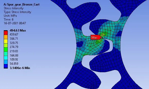
Stress Intensity Plots:
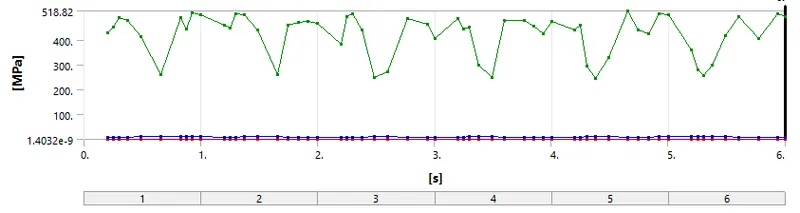
Detailed Stress Intensity Values:
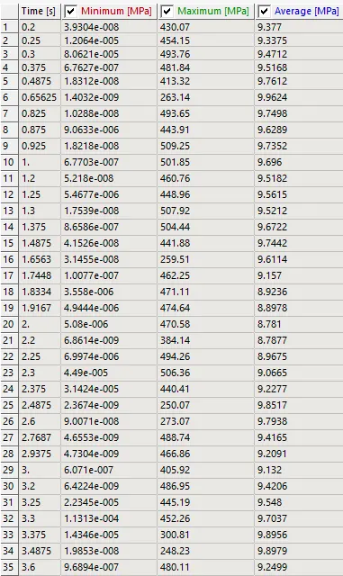
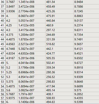
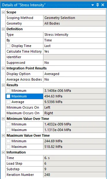
- From the tabular data, we can perceive that the Stress Intensity in gears is 494.63 MPa.
Contact Status Contours:
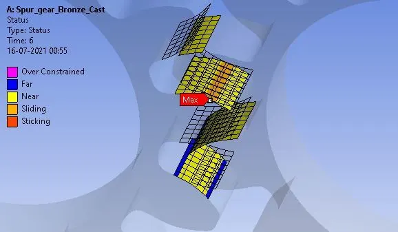
- We can observed that the Orange portion, which represents sliding at contact portion of gears.
- Also we can see that yellow and blue colours represents near and far areas.
- Sticking is happening here.
- Also we can see that there is no over constrained area in gear contacts.
Contact Pressure Contours:
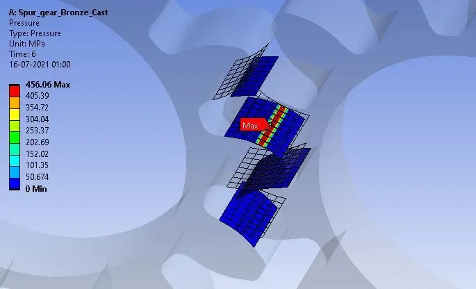
Contact Pressure Plots:
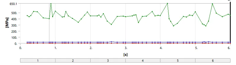
Detailed Contact Pressure Values:
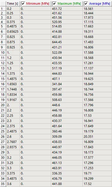
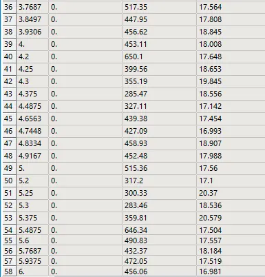
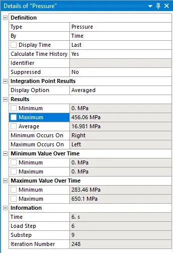
- From the tabular data, we can perceive that the Highest Pressure Generation is 456.06 MPa.
-------------------------------------------------------------------------------------------------------------------
COMPARISON:
| Case | Material | Max. Equivalent (Von Mises) Stress (MPa) |
Max. Total Deformation (MM) |
Max. Stress Intensity (MPa) |
| Case_1 | Cast Iron | 472.05 | 30 | 528.06 |
| Case_2 | Cast Steel | 460.69 | 30 | 517.29 |
| Case_3 | Bronze, Cast | 443.66 | 30 | 494.63 |
-------------------------------------------------------------------------------------------------------------------
- We can refer that the values of Equivalent Stress for all the cases: Case_1>Case_2>Case_3
- Deformation Value is same for all the cases
- Also these same as for the Stress Intensity: Case_1>Case_2>Case_3
-------------------------------------------------------------------------------------------------------------------
CONCLUSION:
- From above Analysis, We can refer that Case_1 (Material: Cast Iron) has highest stress and stress Intensity. Ordinarily Cast Iron gears are easy to manufacture. But main drawback is the wear and tear very fast. So, We can not prefer this Material for the Gears.
- In Manufacturing Industries, there are many machining processes, Heat treatment procedures, Surface finishing operations are available. So, Cast Steel is good material for Gears compared to Cast Iron.
- Bronze, Cast material is generally used for the gear manufacturing. Bronze gears have unique properties like minimal wear in Bronze to Steel surface contact. We can say that Bronze spur gears are used in other devices, where they are mating with the steel Spur gears.
-------------------------------------------------------------------------------------------------------------------
RECOMMENDATION:
So, From the above analysis, We can choose the Material: Bronze, Cast for the Spur Gears.
-------------------------------------------------------------------------------------------------------------------