Week 1 Stress Concentration on a Plate with hole
Question: Analysis of Maximum Deformation and Maximum Stress developed on a plate with hole/holes using ANSYS
-------------------------------------------------------------------------------------------------------------------
CASE: 1
- Open Ansys Workbench (I have used Ansys Workbench version: 2021 R1 Student version)
- Toolbox -> Analysis Systems -> Double click on the
 Static Structural
 - Project Schematic:
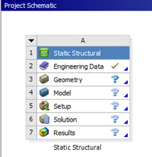
- Engineering Data: Keep the material is “Structural steel” with its all default properties.

- Geometry:
- We can easily import solid model from any software to Ansys workbench just by converting it into a supported file. i.e. STEP, IGES, X_T (Para solid). Also we can use Ansys SpaceClaim for make solid model.
- Here I have used: Solid works 2020 Part file (.sldprt) -> Make STEP file.
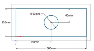
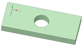
- Switch over Ansys Workbench and then Right click on Geometry -> Import Geometry -> Browse… Specific folder -> Select Supported file. I.e. STEP file.
- Model:
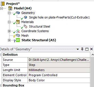
- Double click on Model and appear following screen.
- Now Ansys Mechanical Enterprise starts.
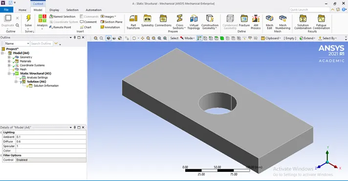
- Check following details:
- Geometry for the Material -> STEP file.
- Material -> Structural steel.
- Mesh:
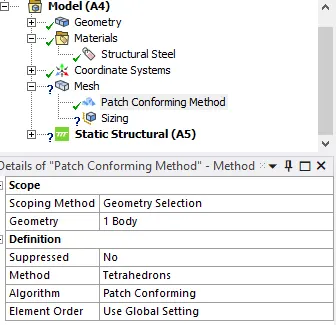
- In the “Mesh”: Right click to Insert -> Method and then change “Tetrahedrons”. Select the geometry from working area -> Apply. Now, we can see the “1 body” under Geometry details.
- Generally Patch conforming method is used for Mesh.
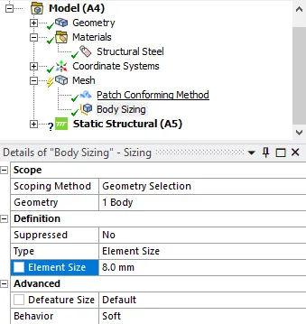
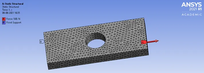
- In the “Mesh” -> Body Sizing -> Set Element size 8.0 mm and afterwards right click to generate the mesh.
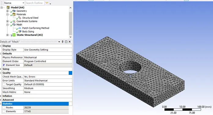
- After generating the “Mesh” in the geometry, it looks like as follows:
- In Statistics: Nodes =26239 and Elements = 17145 observed.
- In “Static Structural”: Right click to Insert -> Fixed support and then Force. Select the Fixed support at left side face shown in following figure and select opposite face for Force. Now, edit the value of Magnitude = 500N.
- In “Solution”: Right click to Insert -> Deformation -> Total Deformation and then Insert -> Stress -> Equivalent (Von-Mises) Stress.
- Click Toolbars -> Solution -> Solve and after solving again click to Total Deformation and Equivalent (Von-Mises) stress and evaluate all the results.
Result (Case-1):
- Total Deformation

| Max. Deformation | 0.00027485 mm |
| Min. Deformation | 0 mm |
- Equivalent (Von-Mises) stress
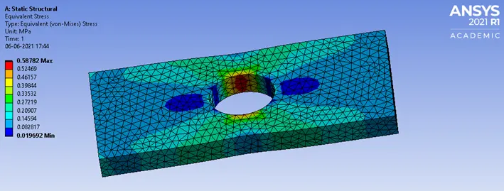
| Max. Stress Concentration | 0.58782 MPa |
| Min. Stress Concentration | 0.019692 MPa |
--------------------------------------------------------------------------------------------------------------------------
CASE: 2
- Open Ansys Workbench (I have used Ansys Workbench version: 2021 R1 Student version)
- Toolbox -> Analysis Systems -> Double click on the Static Structural
- Project Schematic:
- Engineering Data: Keep the material is “Structural steel” with its all default properties.
- Geometry:
- We can easily import solid model from any software to Ansys workbench just by converting it into a supported file. i.e. STEP, IGES, X_T (Para solid). Also we can use Ansys SpaceClaim for make solid model.
- Here I have used: Solid works 2020 Part file (.sldprt) -> Make STEP file.
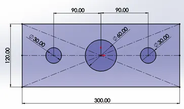
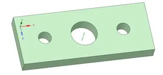
- Switch over Ansys Workbench and then Right click on Geometry -> Import Geometry -> Browse… Specific folder -> Select Supported file. I.e. STEP file.
- Model:
- Double click on Model and appear following screen.
- Now Ansys Mechanical Enterprise starts.
- Check following details:
- Geometry for the Material -> STEP file.
- Material -> Structural steel.
- Mesh:
- In the “Mesh”: Right click to Insert -> Method and then change “Tetrahedrons”. Select the geometry from working area -> Apply. Now, we can see the “1 body” under Geometry details.
- Generally Patch conforming method is used for Mesh.
- In the “Mesh” -> Body Sizing -> Set Element size 8.0 mm and afterwards right click to generate the mesh.
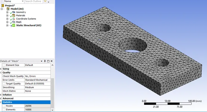
- After generating the “Mesh” in the geometry, it looks like as follows:
- In Statistics: Nodes =26096 and Elements = 16886 observed.
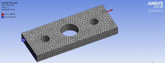
- In “Static Structural”: Right click to Insert -> Fixed support and then Force. Select the Fixed support at left side face shown in following figure and select opposite face for Force. Now, edit the value of Magnitude = 500N.
- In “Solution”: Right click to Insert -> Deformation -> Total Deformation and then Insert -> Stress -> Equivalent (Von-Mises) Stress.
- Click Toolbars -> Solution -> Solve and after solving again click to Total Deformation and Equivalent (Von-Mises) stress and evaluate all the results.
Result (Case-2):
- Total Deformation
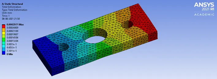
| Max. Deformation | 0.0002971 mm |
| Min. Deformation | 0 mm |
- Equivalent (Von-Mises) stress
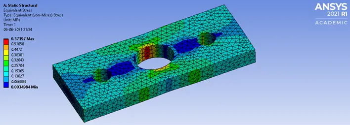
| Max. Stress Concentration | 0.57397 MPa |
| Min. Stress Concentration | 0.0034984 MPa |
Comparison:
- Compare the Deformation and Maximum stress developed on structural steel model for the above 2 cases:
|
Plate with one Hole |
Plate with three holes |
Comparison |
|
|
(Case-1) |
(Case-2) |
|
|
|
Element size (mesh) |
8 |
8 |
|
|
Nodes |
26239 |
26096 |
↓ |
|
Elements |
17145 |
16886 |
↓ |
|
Max. Deformation (mm) |
0.00027485 |
0.0002971 |
↑ |
|
Min. Deformation (mm) |
0 |
0 |
- |
|
Max. Stress (MPa) |
0.58782 |
0.57397 |
↓ |
|
Min. Stress (MPa) |
0.019692 |
0.0034984 |
↓ |
Here, I have observed that:
- Stress Concentration: In Case-1: 58782 MPa and In Case-2: 0.57397 MPa. So, In the Case-1 Stress Concentration is more than compared to Case-2.
- Maximum Deformation: In Case-1: 00027485 mm and In Case-2: 0.0002971 mm. So, In the Case-1 Maximum Deformation is less than compared to Case-2.
From an analysis standpoint, which of the design will you select? Explain why?
- From the Analysis side: Plate with three holes (Case-2) is selected because of less Stress concentration and it undergoes with notable Maximum deformation, when load 500N applied.
- This plate having less weight, because of extra 2 nos. of holes machined.
From a Manufacturing standpoint, which of the design will you select? Explain why?
- From the Manufacturing side: Plate with single hole (Case-1) is selected because of less machining cost, less time consumed during machining, less tooling
- There is no need to change tooling frequently, because of single hole required in the centre compared to three holes (different diameters) on the plate.
Conclusion:
- The structure analysis of both the cases is performed in Ansys 2021 R1. The stress concentration and Maximum deformation are defined particulars.
- Case-2 has less amount of Stress Concentration compared to Case-1. While, Case-2 has more amount of Maximum Deformation compared to Case-1.