Week 1- Mixing Tee
1. Title – Mixing Tee Effectiveness
2. Objective –
- To clean the geometry and mesh it in pre-processing.
- To solve the model with best solver in Ansys solver.
- To generate contour and line plots and analyse it in postprocessor.
3. Introduction –
Computational fluid dynamics is a branch of fluid mechanics, which uses mathematics, physics and computational software to visualize how fluid flows and affects its medium and its neighbours. In CFD mostly computers are used to predict the fluid flow phenomena based on some governing equations like conservation of momentum – Navier stokes equation, conservation of energy etc. In this study we are going to simulating effect of fluid using Ansys fluent software. Ansys fluent is a very important tool in CAE domain, which is allows you to perform all the three major steps of any simulation pre-processing, solving and post-processing. Ansys fluent facilitates for modelling flow, turbulence, heat transfer and chemical reactions. With Ansys we can accomplice more in less time and with less training.
Mixing tee is a device which uses specifically engineered internal geometry to mix two fluid streams into one steam, efficiently. In this study we are going to find effectiveness of mixing tee. Hot air and cold air are going to be mixed in mixing tee. They will have different velocities. We will use two different mixing tee distinguished with length and analyse the effect of length on mixing.
4. Procedure -
There are three major steps to perform any type of simulation as follows pre-processor – it includes geometry clean up and generate best quality mesh. Solving includes applying boundary conditions, initialize and convergence. Last step is post processor which includes generate plots, contours, vectors to analyse results. In this study we are going to follow all three steps to find out effectiveness of mixing tee. The following steps to be followed –
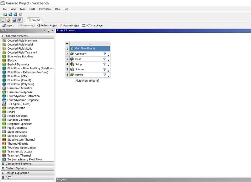
1. Open Ansys workbench, make new project by clicking on Fluid flow (Fluent)
2.Double click on geometry it will redirect you to design modeler, as i did not have the mixing tee files with me so i tried making it using cylinders as shown below, As i have made it so there is no solid part with it.
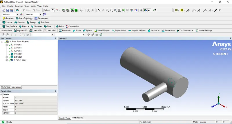
else if you import the file from CAD you have to take care that no solid part is there for that you have to extract the volume.
3. Going Back to work Bench you will see the Geometry as green ticked that means its done and now we can procced for meshing.
4. For Meshing double click on it, once it is open click on each face and the press 'N' to name all the faces respectivelly
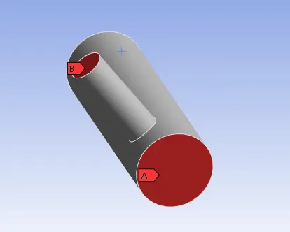
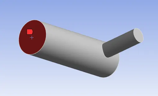
A and B is named as inlet and the other side is outlet. Rest all is selected and named as Wall
Once the naming is done then we click on Mesh to generate, the generated mesh is shown below.
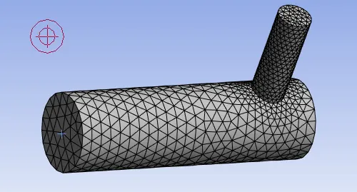
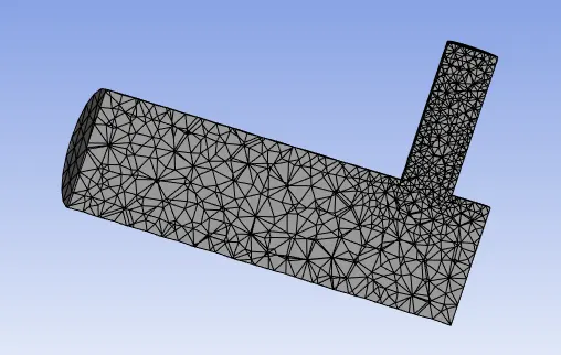
Once the mesh is created we can cut a section to see the internal mesh.
We can even check the quality of the mesh that is being created for that click on Quality and make mesh metric to element quality
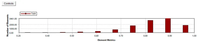
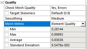
Coming back to work bench you will see that the mesh is green ticked now, that means the mesh is ok.
5. Now Double click on setup, this is how it will look when it opens.
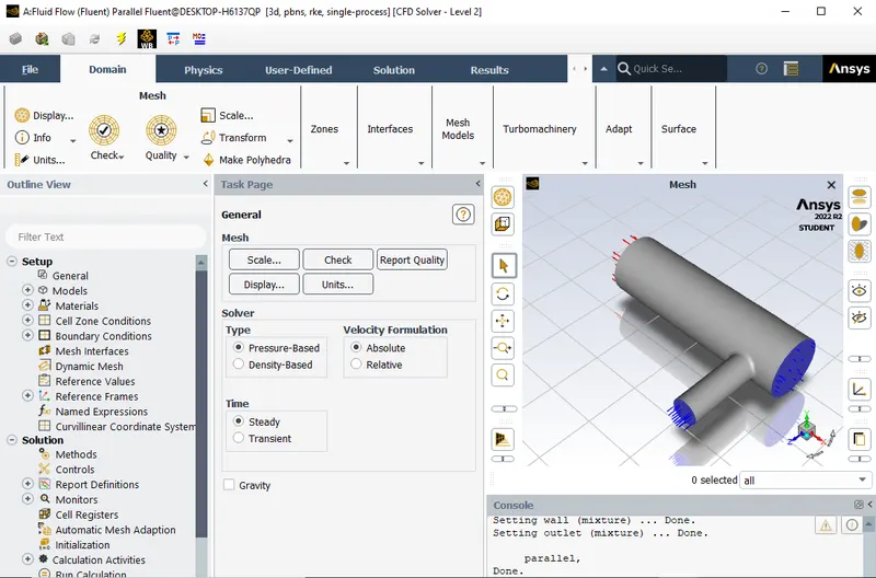
First click on check to see the mesh is ok.
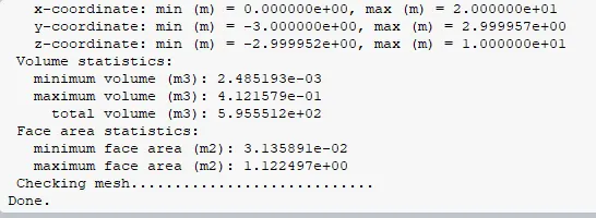
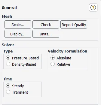
Once its done we can move forward. then we will go to physics tab and click on general, there we select steady state and pressure based solver,
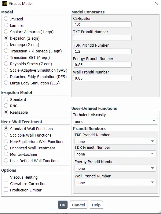
then click on Viscous and K-epsilon model,
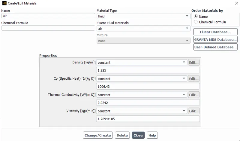
Then click on material here it should be air,
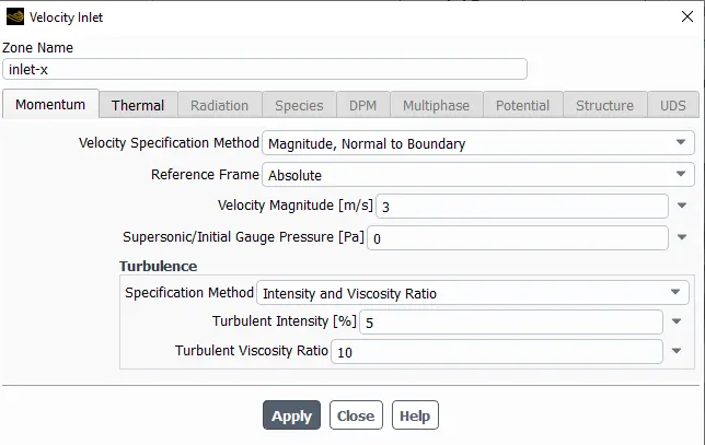
then we will start giving the boundary conditions,
Hot Air inlet boundary condition: Temp 36C
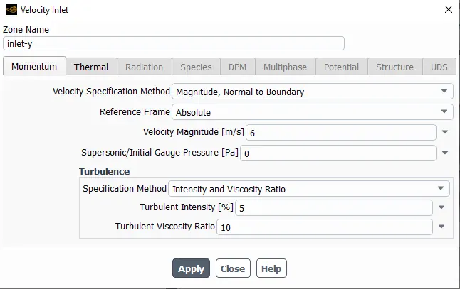
Cold Air inlet boundary condition: Temp 19C
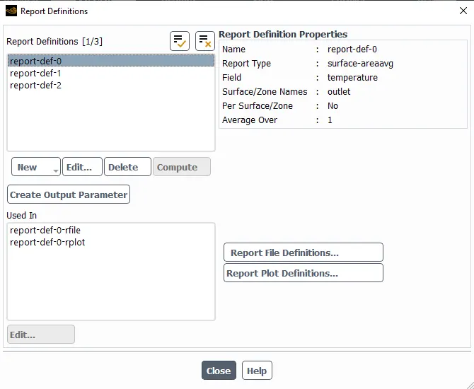
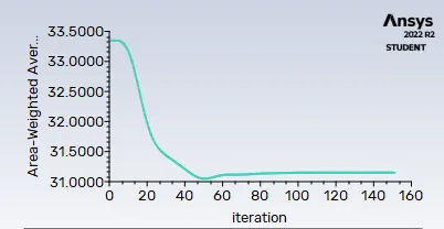
To add the output go to solution tab and click on defination, Add cell count, Temperature and standard deviation,
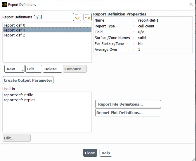
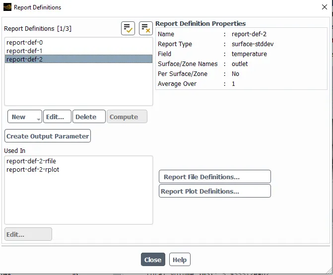
Once this is done click on Hybrid Initialization and start it.
Initialize using the hybrid initialization method.
Checking case topology...
-This case has both inlets & outlets
-Pressure information is not available at the boundaries.
Case will be initialized with constant pressure
iter scalar-0
1. 1.000000e+00
2. 1.689152e-03
3. 2.688286e-04
4. 6.184595e-05
5. 5.873532e-05
6. 1.821200e-05
7. 3.994224e-05
8. 8.585476e-06
9. 1.331569e-05
10. 3.340321e-06
Hybrid initialization is done.
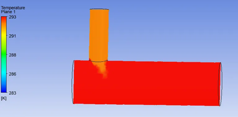
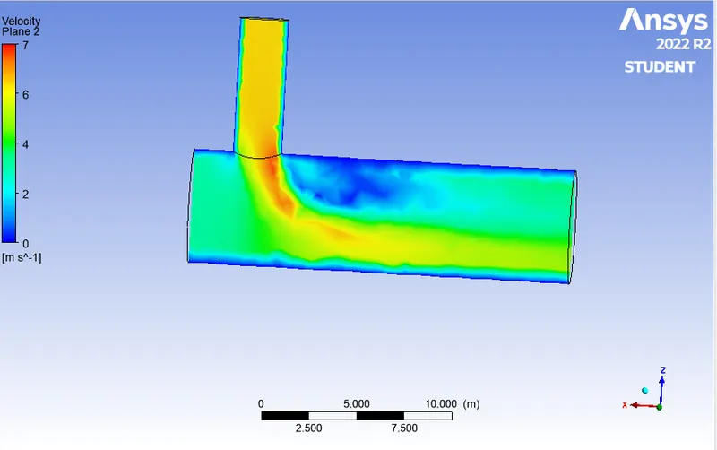
Case 1.A: Momentum ratio 2
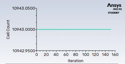
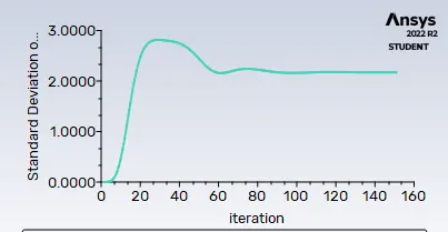
Case 1.B: Momentum ratio= 4
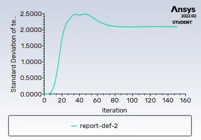
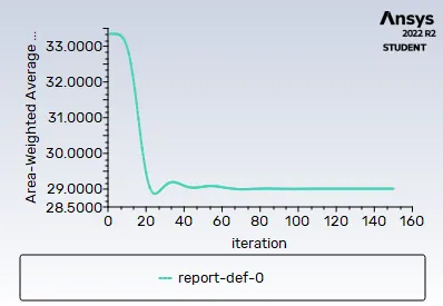
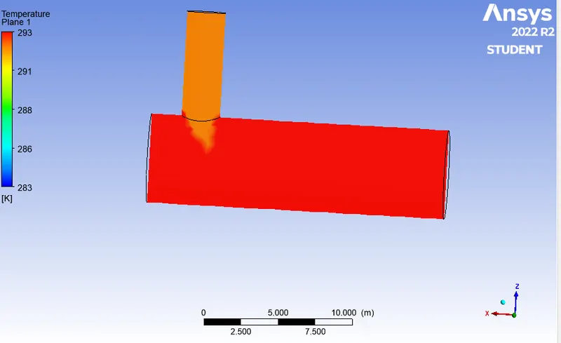
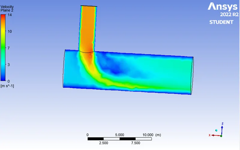
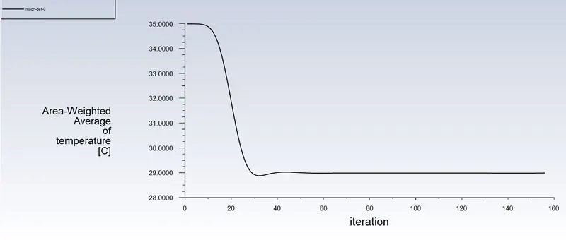
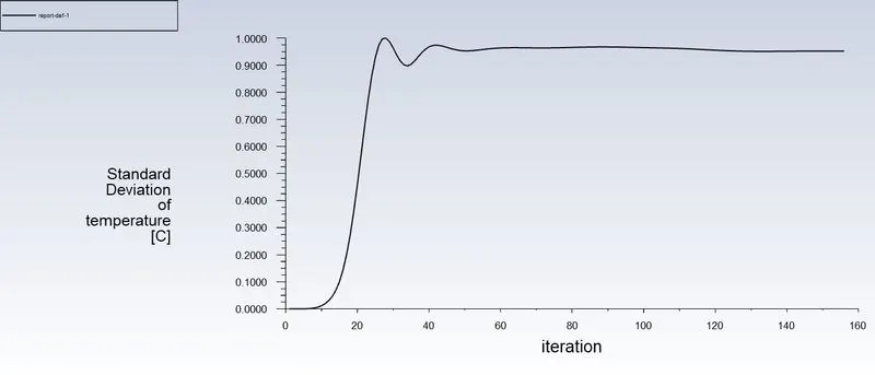
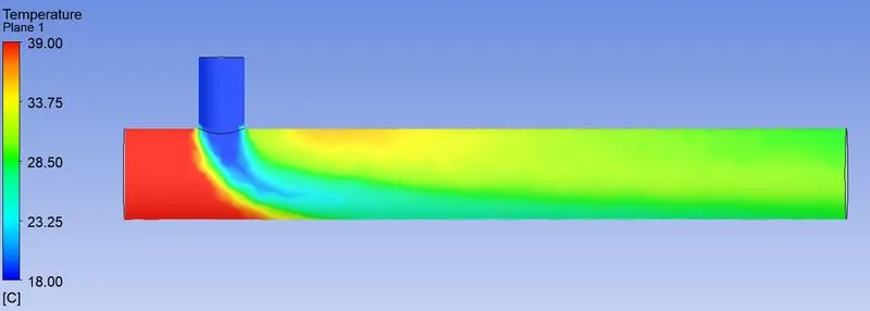
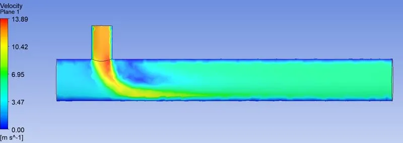
Case 2 - In this case long mixing tee is used, which was mixing two fluid with temperature 36C and 19C. Velocity of hot fluid was 3m/s and cold fluid was 12m/s.
We used realized k-epsilon model and solution was converged after 156 iterations.
6. Conclusion –
Ansys fluent is high performance CFD software recognized for accuracy, robustness etc. it is not confined to only aerospace and mechanical domain, it has various application like to simulation of calculation of air flow on air craft wing, combustion in furnace, bubble columns in oil refineries, combustion in IC engine etc. In this study we performed simulation on simple geometry of mixing tee and got insights of various feature of fluent. we can conclude by analysing graph that If momentum ratio is increased, outlet temperature will decrease and there is no effect of velocity even though length is increased.