Week 1- Mixing Tee
CHALLENGE REPORT :
AIM :
In these challenge we have to created two versions of the mixing tee.
OBJECTIVE:
* To created two versions of the mixing tee.
* To set up steady-state simulations to compare the mixing effectiveness when hot inlet temperature is 360C & the Cold inlet is at 190C.
* To Use the k-epsilon and k-omega SST model for the first case.
* Case 1
- Short mixing tee with a hot inlet velocity of 3m/s.
- Momentum ratio of 2, 4.
- * Case 2
- Long mixing tee with a hot inlet velocity of 3m/s.
- Momentum ratio of 2, 4.
INTRODUCTION :
Mixing tees are widely used in the petrochemical industry, in which two fluid streams with different physical and/or chemical properties mix together. When there is a large temperature difference between the two streams, large metal temperature fluctuations can occur in the region where the two streams meet if proper design steps are not taken. The temperature fluctuations in the metal may lead to thermal fatigue of the pressure boundary piping. If through-wall cracking occurs, the fluid may leak, possibly causing a fire and damage. It is therefore imperative to make sure that the temperature fluctuations are such that the piping system can withstand them. Options can include improving the mixing of the two streams to reduce the temperature fluctuations through redesign of the piping system such that the momentum ratio of the two fluid streams is favorable to rapid mixing, or to install devices that protect the pressure boundary piping.
A tee junction simulation is used here to evalute the change in temparature by mixing same fluid at different temparatures and with different inlet velocities through two inlet pipe which are perpendicular to each other.The simulation is done in two cases, for each cases only geometry varies (one is shorter than the other).Also for each cases we will be simulating for momentum ratio of 2 and 4.
The workflow in Ansys fluent is as follows
Gemoetry -> Mesh -> Setup -> Solution -> Results
PROCEDURE :
* Select the fluid flow(fluent) modul in the Work space of ANSYS fluent software.
* Then select the geomentry option which is used to import the model used to perform the mixied tee and it can done using the spaceclaim option.
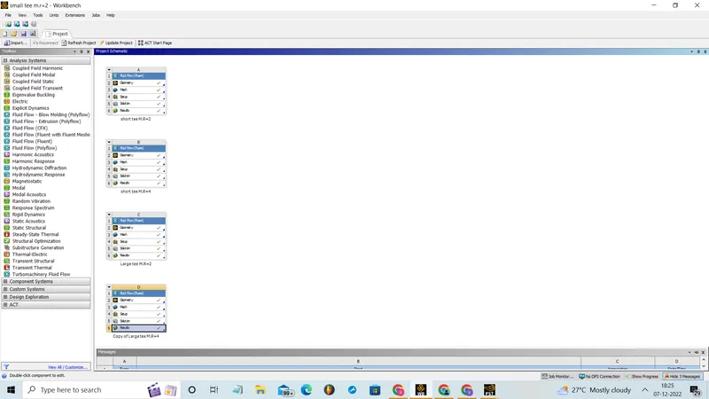
* Next we have to create the enclosed volume using the volume extract command in the prepare option in the space claim.
* The suppress the shell of the model which is already present.
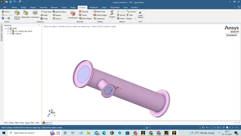
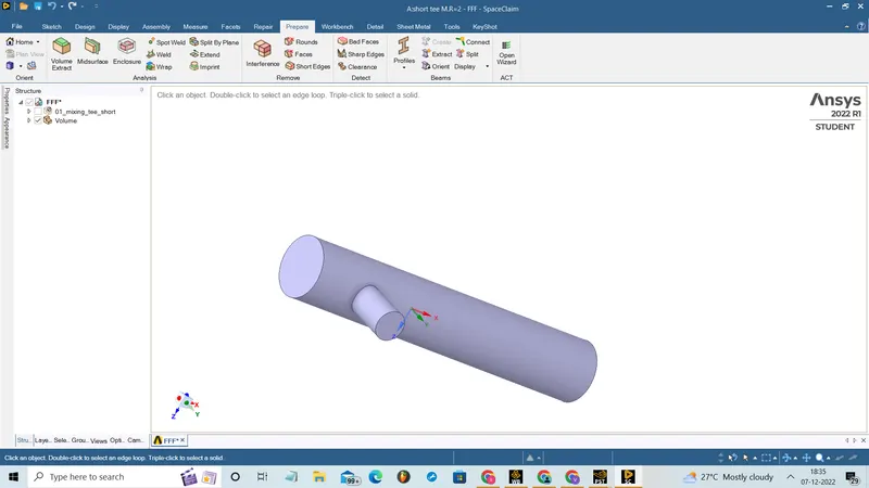
* Then using the mesh option mesh the model with 2mm length using the generate mesh command .
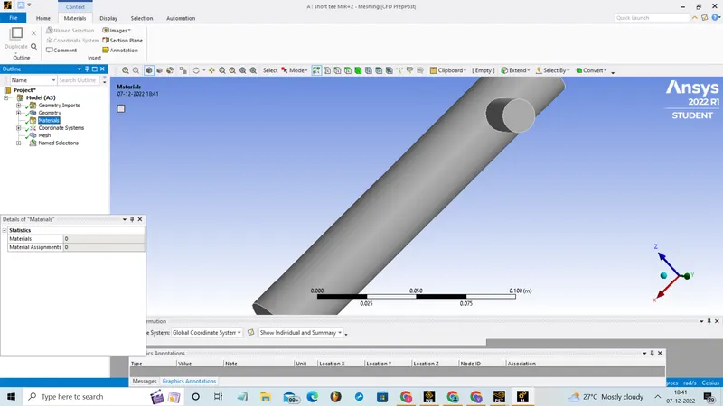
* By selecting the faces assign the names to the opening like inlet X, inlet Y, outlet using the name selection command.
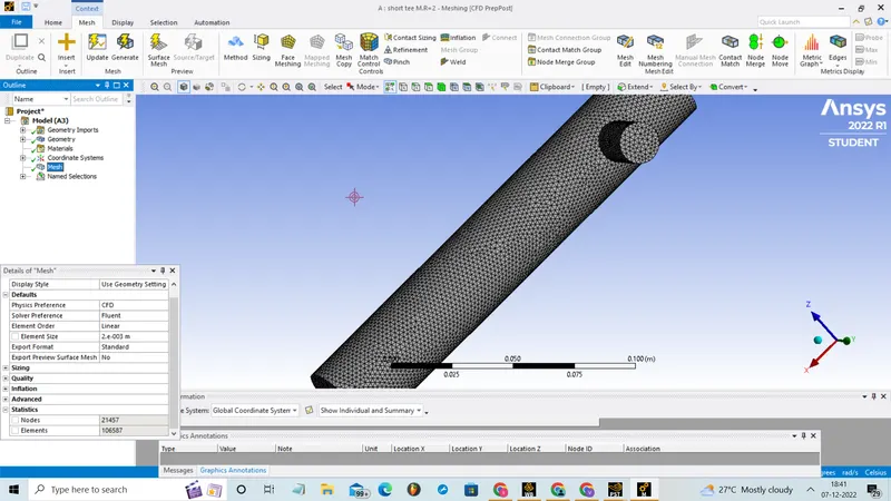
* We can also check the Quality of the mesh and statistics shows the number of nodes, number of elements present on it.
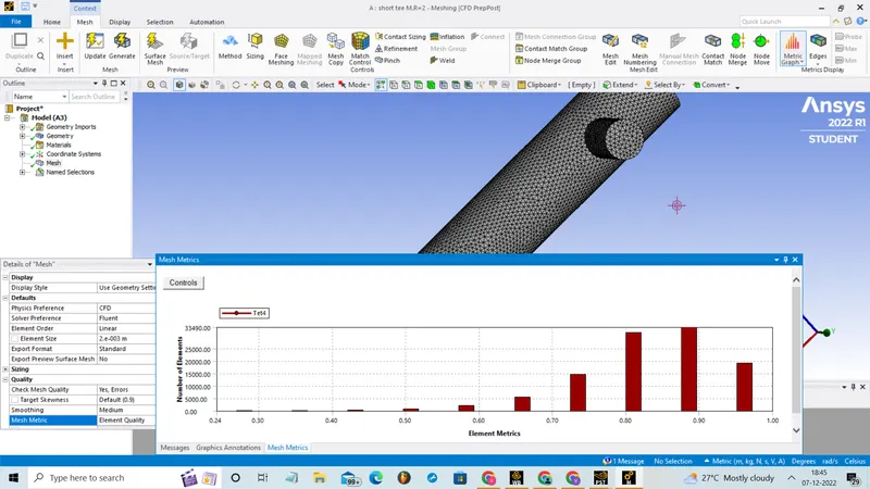
* Then update the mesh data.
* Next some of the parameters as to be set using the setup option.
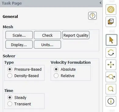
* In these we use the pressure based steady state simulation, so choose these options on task page.
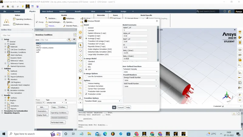
* Select the realizable k-epsilon model by opening the physics menu and select viscous model.
* Select air as working fluid by clicking the material option.
* Then we have to set the boundary conditions by the option boundries . select the inlet X and set velocity as 3m/s and temperature as 36C.
* For inlet X, set velocity as 6m/s and temperature as 19C.
* And for the outlet default value can be allowed.
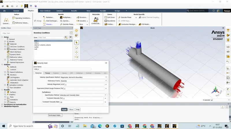
* Then solution set up as to be made to get the temperature report of outlet and the standard deviation of temperature of outlet.
* These can be done by selecting solutions tab and select definition and select area weighted average. In these opened menu select temperature as field variable. Similarly select standard deviation in definitions menu.
* Select initialization, hybride initialize is used to calculate approximate values of velocity and pressure.
* initialy give 200 iteration and if the solution is not converged and then increase the iteration and calculate it.
* Then insert a XY plane in wall by clicking on plane in location option of insert.
* Create the contours for temperature and velocity in the created plane.
* In the result option we can create the plots for temperature and velocity which is used to compare both the case.
* For the case 2 we can dubilicate the case 1 and just change the velocity as 12m/s in the setup option.
* Similar, procedure as to carried out or large tee model.
RESULT :
Short mixing tee:
CASE1:
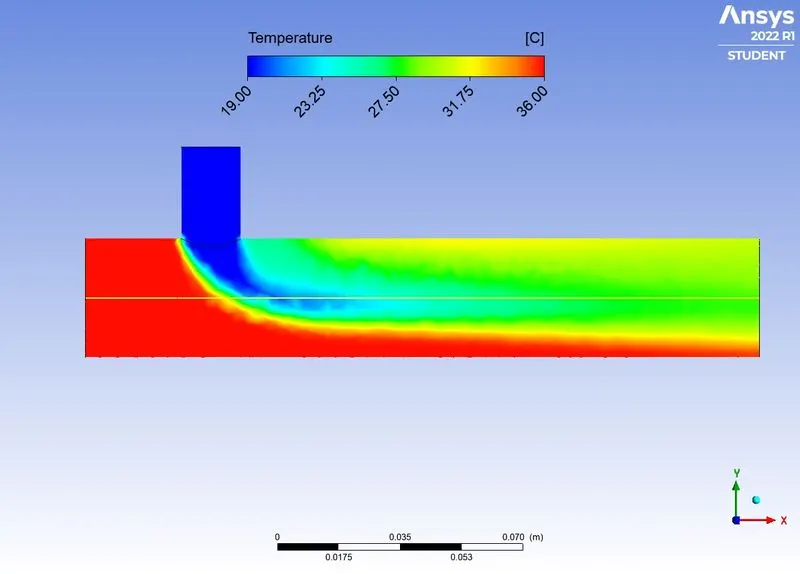
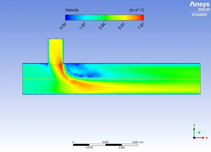
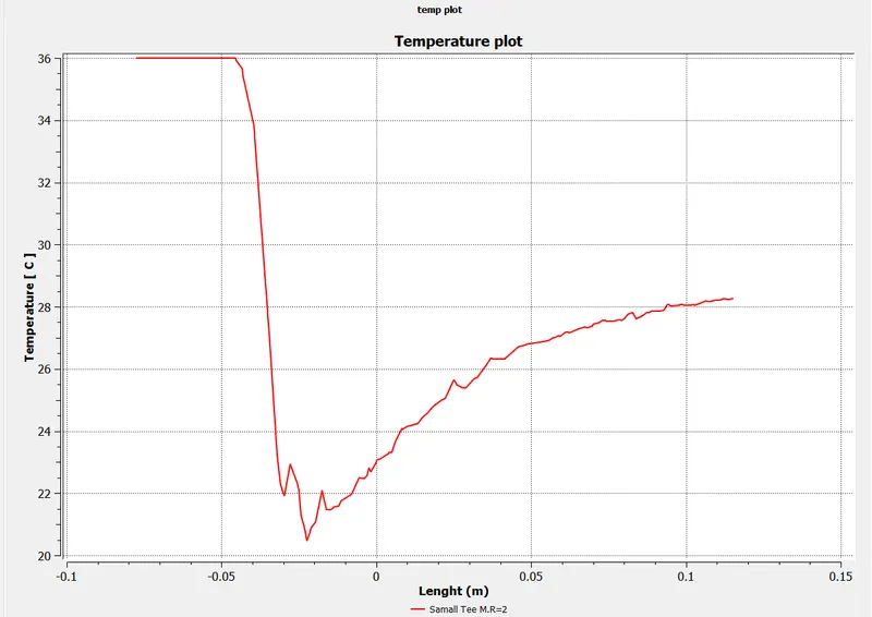
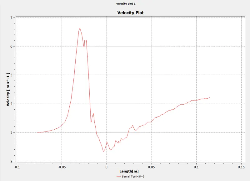
In these mixing of two fluid with temperature 36C and 19C take place and the velocity of hot fluid was 3m/s and cold fluid was 6m/s.
Plot and contours from model:
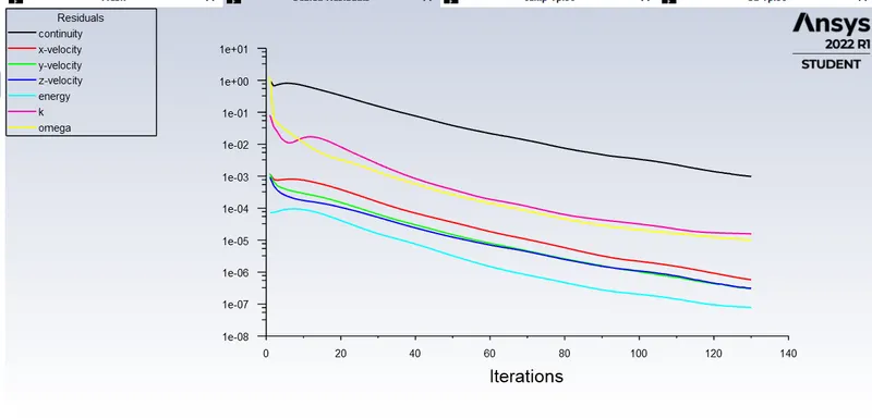
Residuals:
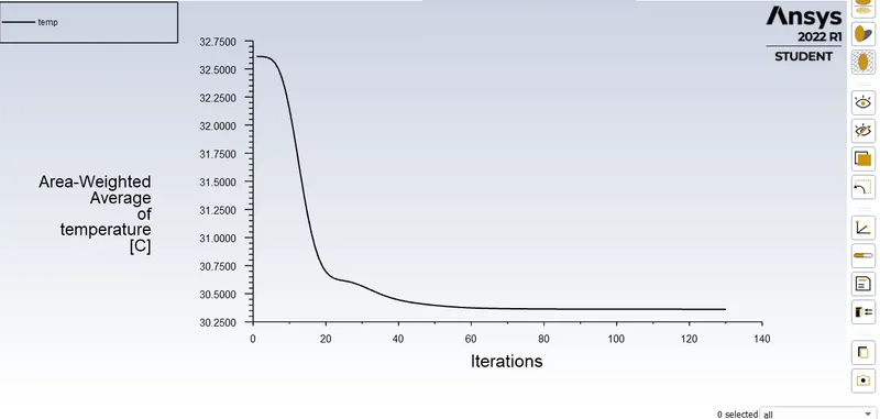
Average Temperature vs Iterations:
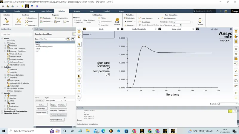
Standard Deviation of Temperature vs Iteration:
Temperature contour:
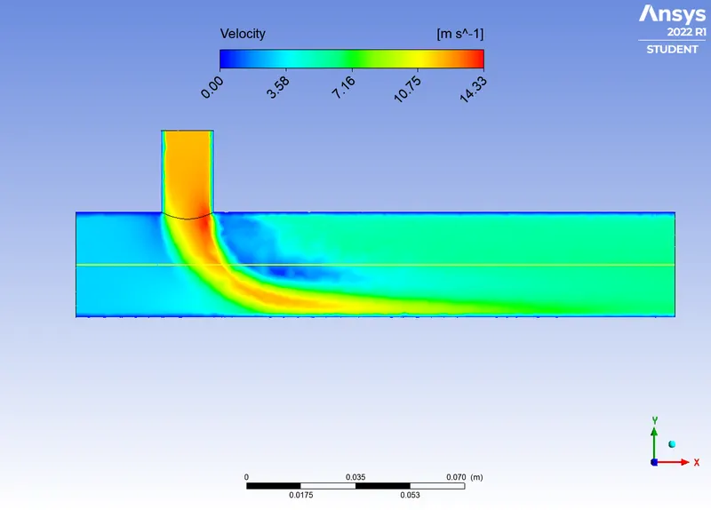
Velocity contour:
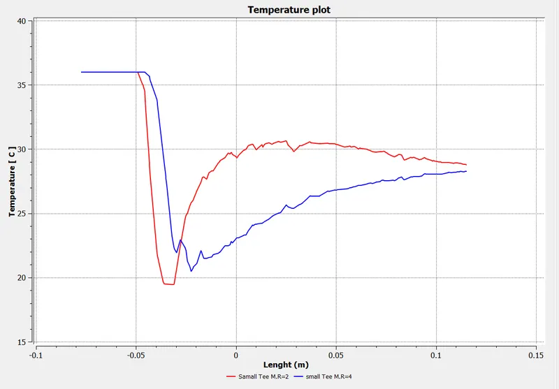
TEMPERATURE PLOT :
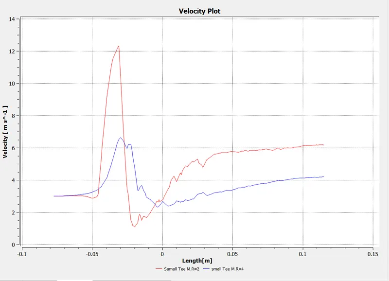
VELOCITY PLOT :
CASE2:
In these mixing of two fluid with temperature 36C and 19C take place and the velocity of hot fluid was 3m/s and cold fluid was 12m/s.
Plot and contours from model:
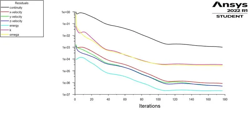
Residuals:
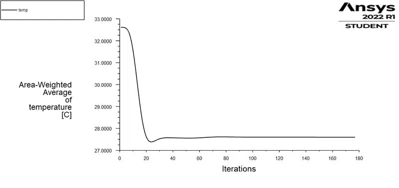
Average Temperature vs Iterations:
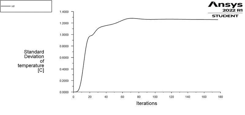
Standard Deviation of Temperature vs Iteration:
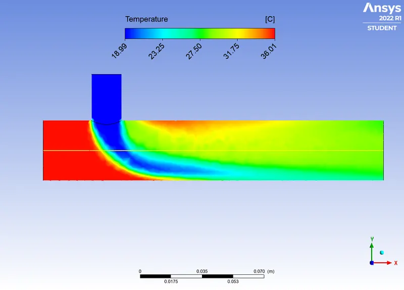
Temperature contour:
Velocity contour:
COMPARISION OF M.R=2 AND M.R=4 FOR TEMPERATURE PLOT :
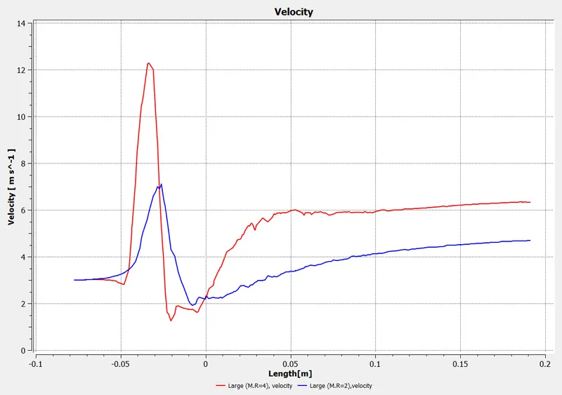
COMPARISION OF M.R=2 AND M.R=4 FOR VELOCITY PLOT :
Long mixing tee:
CASE1:
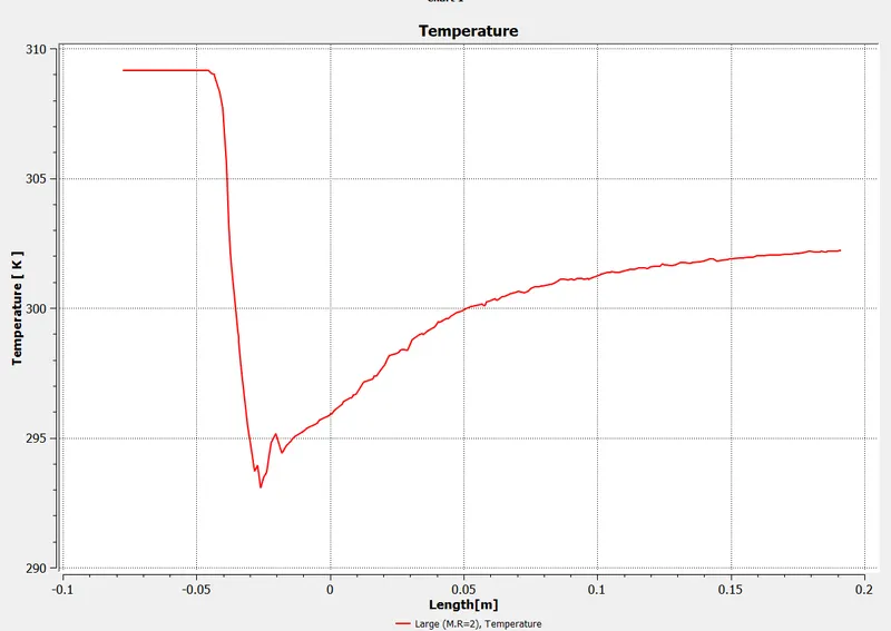
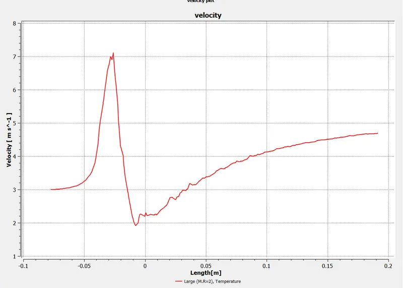
In these mixing of two fluid with temperature 36C and 19C take place and the velocity of hot fluid was 3m/s and cold fluid was 6m/s.
Plot and contours from model:
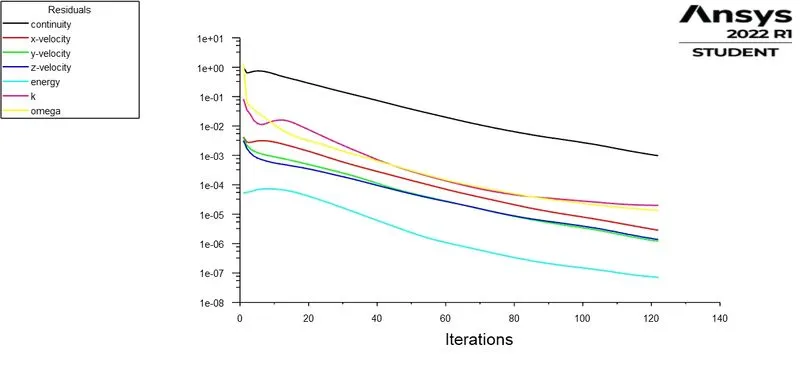
Residuals:
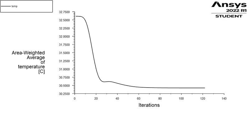
Average Temperature vs Iterations:
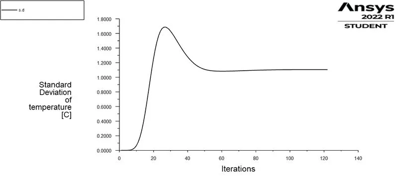
Standard Deviation of Temperature vs Iteration:
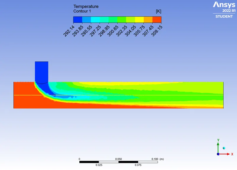
Temperature contour:
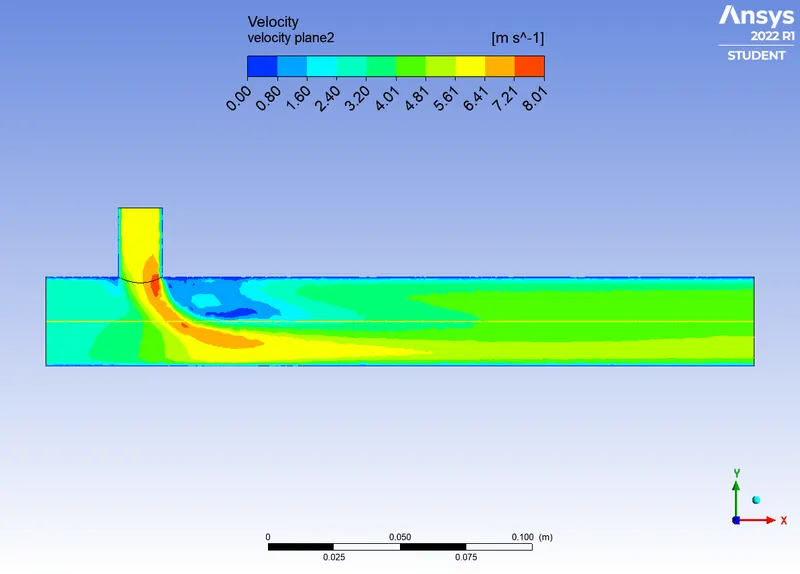
Velocity contour:
TEMPERATURE PLOT :
VELOCITY PLOT :
CASE2:
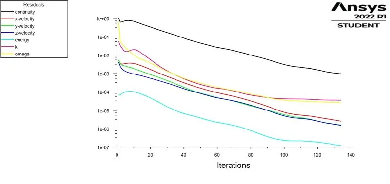
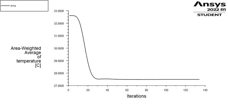
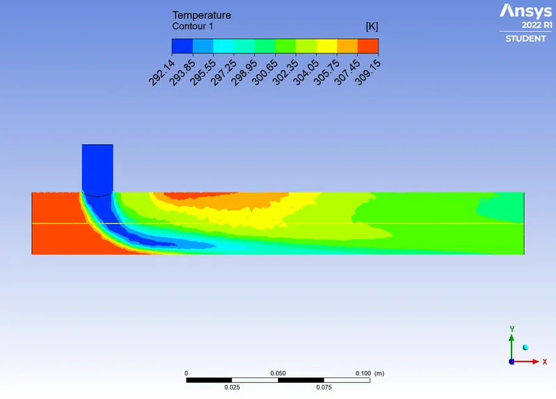
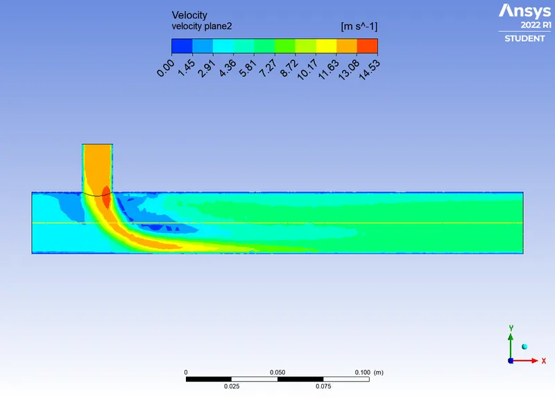
In these mixing of two fluid with temperature 36C and 19C take place and the velocity of hot fluid was 3m/s and cold fluid was 12m/s.
Plot and contours from model:
Residuals:
Average Temperature vs Iterations:
Standard Deviation of Temperature vs Iteration:
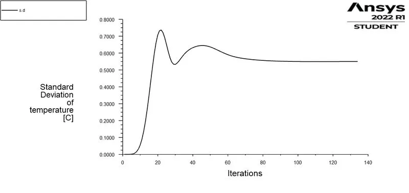
Temperature contour:
Velocity contour:
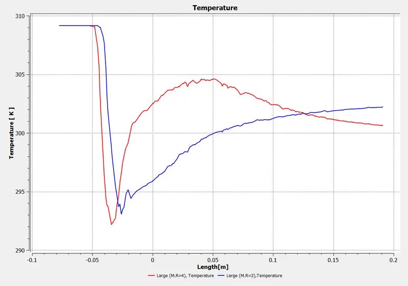
COMPARISION OF M.R=2 AND M.R=4 FOR TEMPERATURE PLOT :
COMPARISION OF M.R=2 AND M.R=4 FOR VELOCITY PLOT :
CONCLUSION:
- k- epsilon model predicts well far from the boundaries (wall) and k- omega model predicts well near the wall. Even though it depends on Y+. Therefore, K-epsilon model is majorly used for free flow away from the wall and as in this project, there is no dealing with the wall of the mixing tee for change in temperature along the length of it, so K-omega model was chosen for further simulations.
- As seen in the Case-1-a and Case-1-b, the temperature at the outlet drops down significantly due to high velocity of cold air from the inlet. This is possible due to the turbulent mixing at the tee joint between hot air and cold air because of the high velocity of cold air., which is not possible in case of low-velocity cold air.