Week 1- Mixing Tee
PROJECT-
- Mixing tee using Ansys Fluent.
THEORY-
- Ansys Fluent is the industry leading CFD software for turbomachinery applications. Ansys fluent advanced physics modeling capabilities help engineers solve the most complex challenges in turbomachinery applications.
Case -1
- Short mixing tee with a hot inlet velocity of 3m/s.
- Momentum ratio of 2, 4.
- Long mixing tee with a hot inlet velocity of 3m/s.
- Momentum ratio of 2, 4.
- As per the results we are going to compare the following values from the 2 cases and the parameters are as follow as,
- Cell count.
- Average outlet temperature.
- Number of iterations for convergence.
PROCEDURE-
-There are three major steps to perform in Ansys Workbench , there are seting up a gemotry and generate a mesh using the gemotry and given boundary condition. At last we are post processing which genrate plot , contour and velocity to analyse the result.
SHORT TEE-
1-Geometry setup.
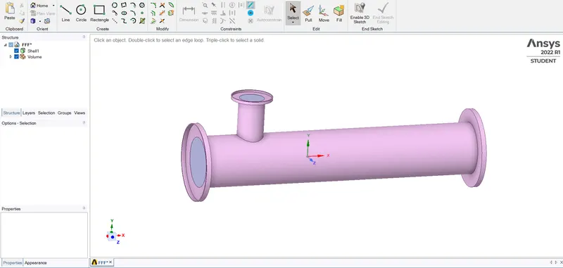
1-The first step is open spaceclaim using Ansys workbench as shown in below figure,
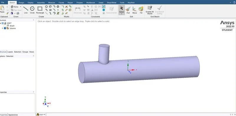
 2-In this domain we are interested in performing Fluid flow analysis,so we used the volume extraction option to extract the fluid volume from the geometry. Then we supreessed the unwanted solid . The final extracted fluid volume in below figure,
2-Mesh Generation
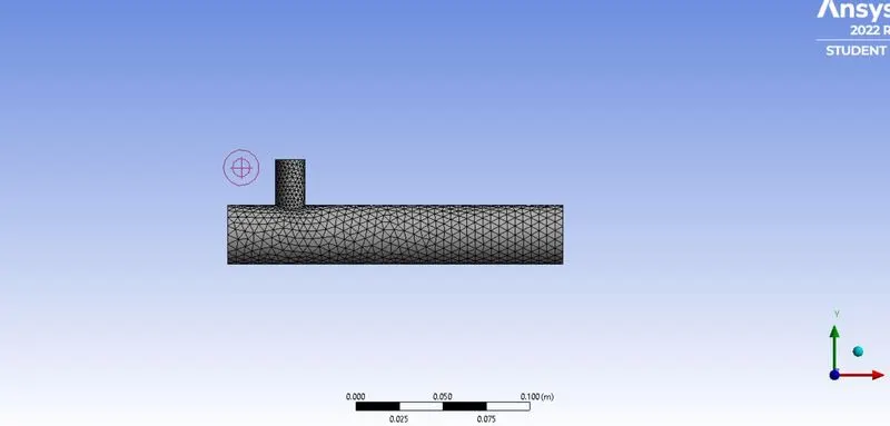
Here we first select names for the faces as, Inlet-y,inlet-x,outlet and walls are defined using name selection option and then generate the mesh .
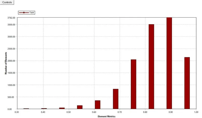
-After genrating sthe mesh , the number of nodes and elements are investigated using the statics option . then the mesh quality is checked by choosing the mesh metrics option in quality section and the mesh quality shoud not be less than 30 as shown in the below figure.
3-Setup -
Table-1(Short tee)
| SETUPS | FOR K-EPSILON | FOR K-OMEGA |
| SOLVER TYPES | Pressuree based | Pressure based |
| VELOCITY FORMULATION | Absolute | Absolute |
| TIME | Steady | Steady |
| VISCOUS MODEL | K-epsilon (realizable) | K-omega (SST model) |
| MATERIAL | Air | Air |
| CELL ZONE | Fluid type(air) | Fluid type (air) |
| BOUNDARIES CONDITION |
i- For inlet-x (vlocity_inlet) Temperature-36(C) Velocity- 3 m/s ii-For inlet-y(Velocity_inlet) Temperature -19(C) Velocity- 6m/s iii-For Outlet(Pressure_outlet) Gauge pressure - 0(pa) iv-Walls-Fixed |
i- For inlet-x (vlocity_inlet) Temperature-36(C) Velocity- 3 m/s ii-For inlet-y(Velocity_inlet) Temperature -19(C) Velocity- 6m/s iii-For Outlet(Pressure_outlet) Gauge pressure - 0(pa) iv-Walls-Fixed |
SOLUTION-
-After setup all the boundary conditions , we are now going for geting solution.
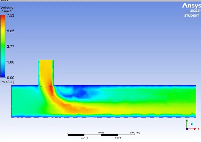
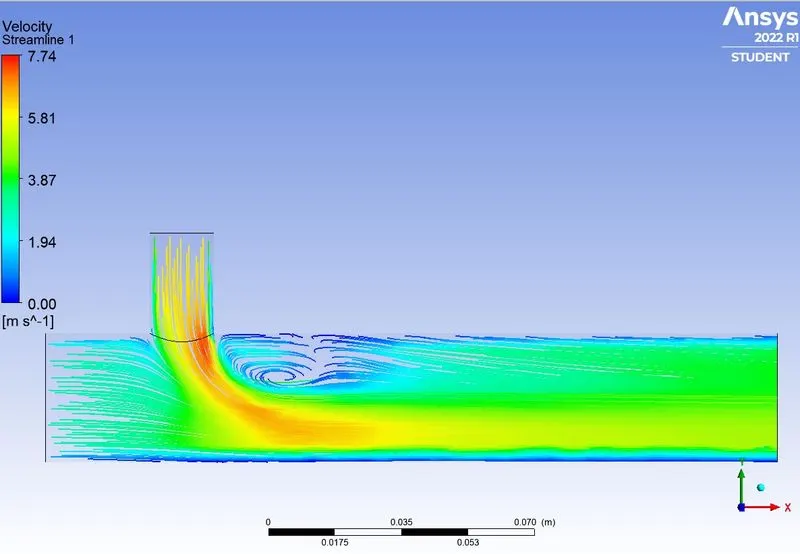
-For the Case 1(a) which we are mixing two fluid with temprature 36 and 19 degree celcius , and velocity in inlet-x is 3m/s and in inlet-y is 6m/s for both(k-eplision and k-omega).
CASE 1(a)-
RESULT FOR(K-EPSILON) -
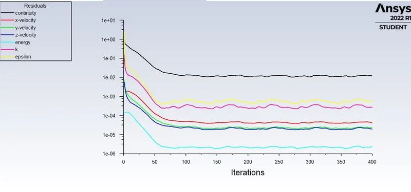
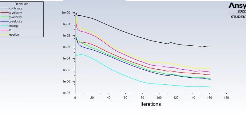
I-Residual Plot-
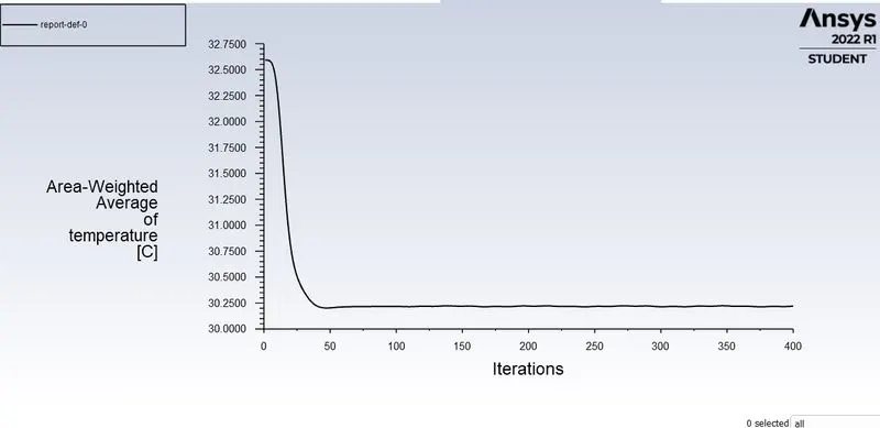
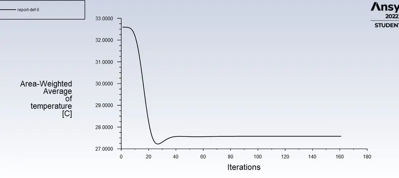
AREA WEIGHTED AVERAGE-
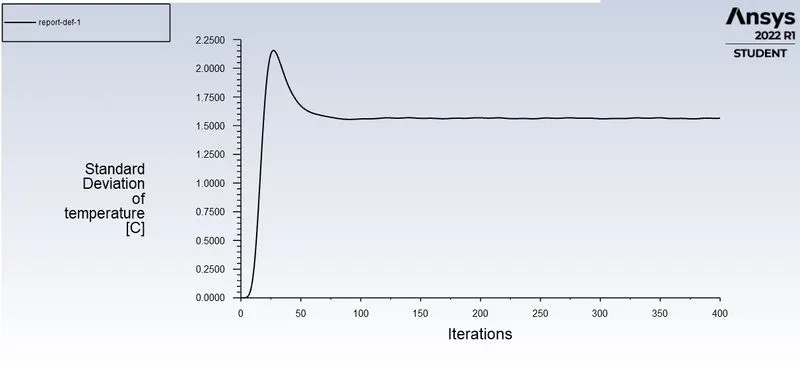
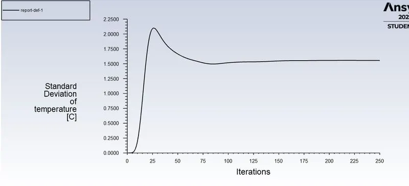
STANDARD DEVIATION-
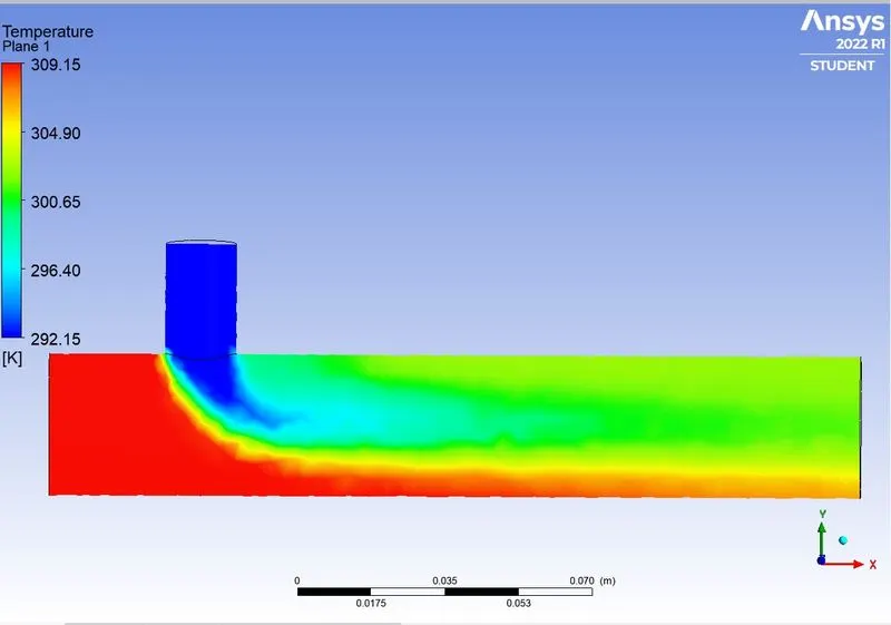
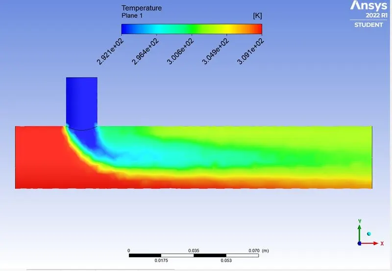
TEMPRATURE CONTOUR-
VELOCITY CONTOUR-
VELOCITY STREAMLINE -
RESULTS FOR (K-OMEGA)-
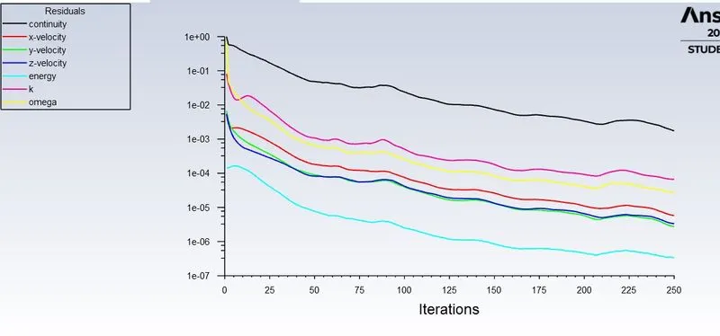
RESIDUAL PLOT-
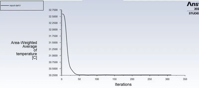
AREA WEIGHTED AVERAGE-
STANDARD DEVIATION-
TEMPRATURE CONTOUR-
VELOCITY CONTOUR-
VELOCITY STREMLINE-
FOR CASE-1(B)
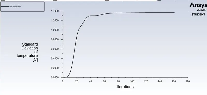
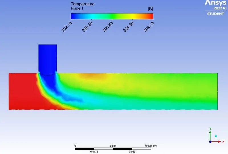
-In the this case 1(b) , which we mixing two fluid with temprature 36 and 19 degree celcius , velocity of inlet-x is 3m/s and 12m/s for inlet-y(both k-epsilon and k-omega) .Momentum ratio-4
RESULT FOR(K-EPSILON) -
I-Residual Plot-
AREA WEIGHTED AVERAGE-
STANDARD DEVIATION-
TEMPRATURE CONTOUR-
VELOCITY CONTOUR-
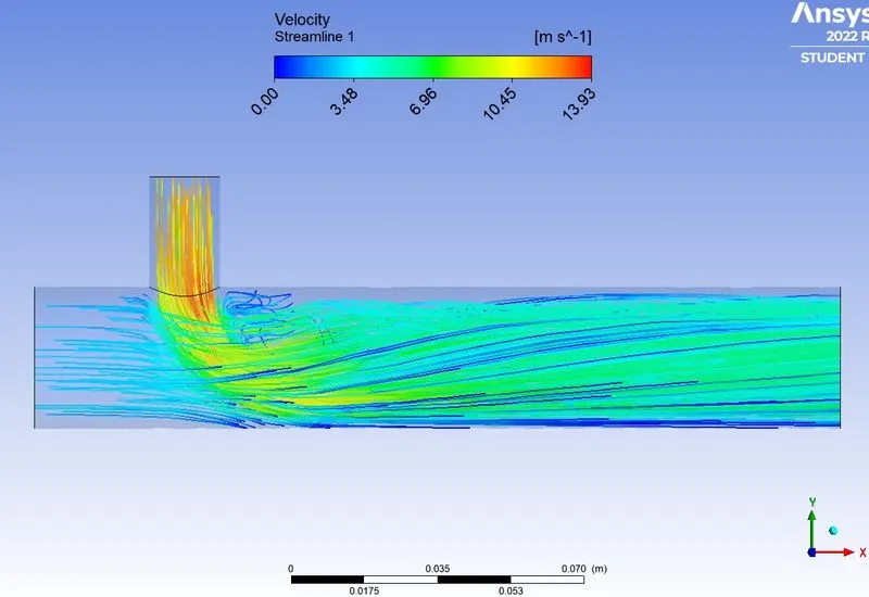
VELOCITY STREAMLINE -
RESULTS FOR (K-OMEGA)-
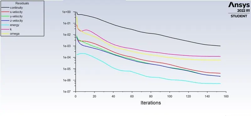
RESIDUAL PLOT-
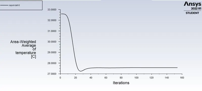
AREA WEIGHTED AVERAGE-
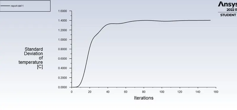
STANDARD DEVIATION-
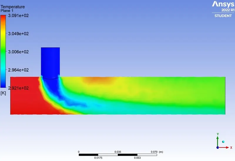
TEMPRATURE CONTOUR-
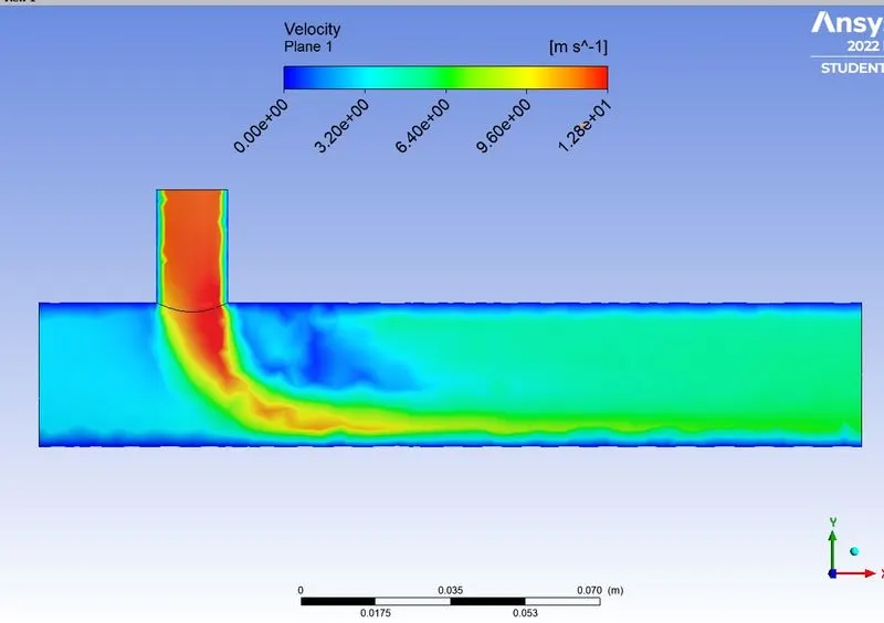
VELOCITY CONTOUR-
VELOCITY STREAMLINE -
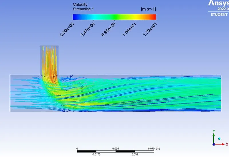
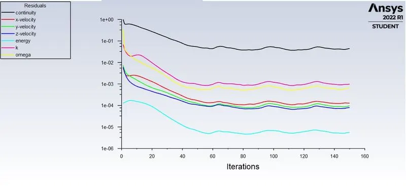
-From above cases we conclude that k-epsilon was given better results because solution was converged after few itteration , where as after using k-omega solution was not converged , k- omeg ais prefered in studiying behaviour nera walls, in k epsilon is prefered to study fluid away from walls.
2-LONG TEE
1-Geometry setup.
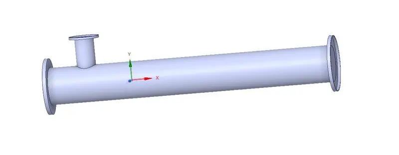
1-The first step is open spaceclaim using Ansys workbench as shown in below figure,
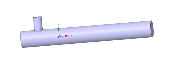
2-In this domain we are interested in performing Fluid flow analysis,so we used the volume extraction option to extract the fluid volume from the geometry. Then we supreessed the unwanted solid . The final extracted fluid volume in below figure,
2-Mesh Generation
Here we first select names for the faces as, Inlet-y,inlet-x,outlet and walls are defined using name selection option and then generate the mesh .
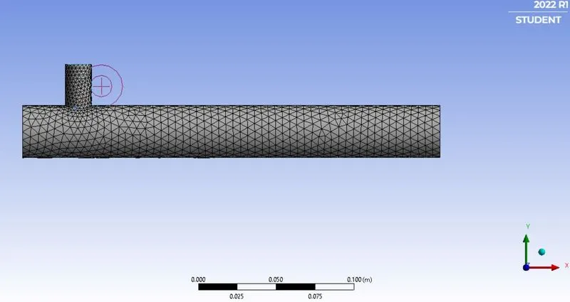
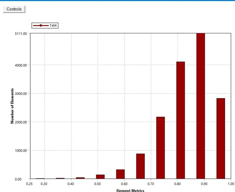
-After genrating sthe mesh , the number of nodes and elements are investigated using the statics option . then the mesh quality is checked by choosing the mesh metrics option in quality section and the mesh quality shoud not be less than 30 as shown in the below figure.
3-Setup -
Table-1(Long tee)
| SETUPS | FOR K-EPSILON | FOR K-OMEGA |
| SOLVER TYPES | Pressuree based | Pressure based |
| VELOCITY FORMULATION | Absolute | Absolute |
| TIME | Steady | Steady |
| VISCOUS MODEL | K-epsilon (realizable) | K-omega (SST model) |
| MATERIAL | Air | Air |
| CELL ZONE | Fluid type(air) | Fluid type (air) |
| BOUNDARIES CONDITION |
i- For inlet-x (vlocity_inlet) Temperature-36(C) Velocity- 3 m/s ii-For inlet-y(Velocity_inlet) Temperature -19(C) Velocity- 6m/s iii-For Outlet(Pressure_outlet) Gauge pressure - 0(pa) iv-Walls-Fixed |
i- For inlet-x (vlocity_inlet) Temperature-36(C) Velocity- 3 m/s ii-For inlet-y(Velocity_inlet) Temperature -19(C) Velocity- 12m/s iii-For Outlet(Pressure_outlet) Gauge pressure - 0(pa) iv-Walls-Fixed |
SOLUTION-
-After setup all the boundary conditions , we are now going for geting solution.
-For the Case 1(a) which we are mixing two fluid with temprature 36 and 19 degree celcius , and velocity in inlet-x is 3m/s and in inlet-y is 6m/s for both(k-eplision and k-omega).
CASE -2
RESULT FOR(K-EPSILON) -
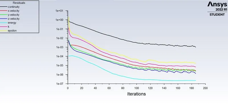
I-Residual Plot-
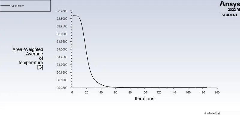
AREA WEIGHTED AVERAGE-
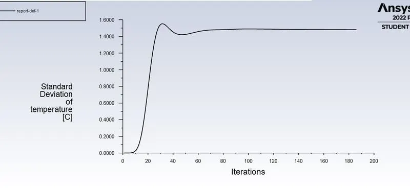
STANDARD DEVIATION-
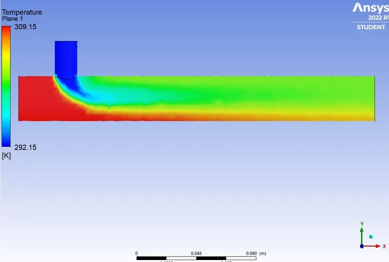
TEMPRATURE CONTOUR-
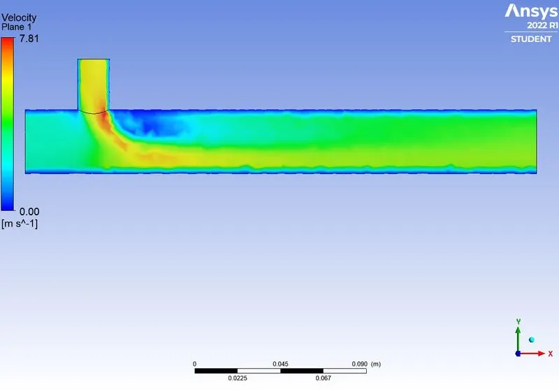
VELOCITY CONTOUR-
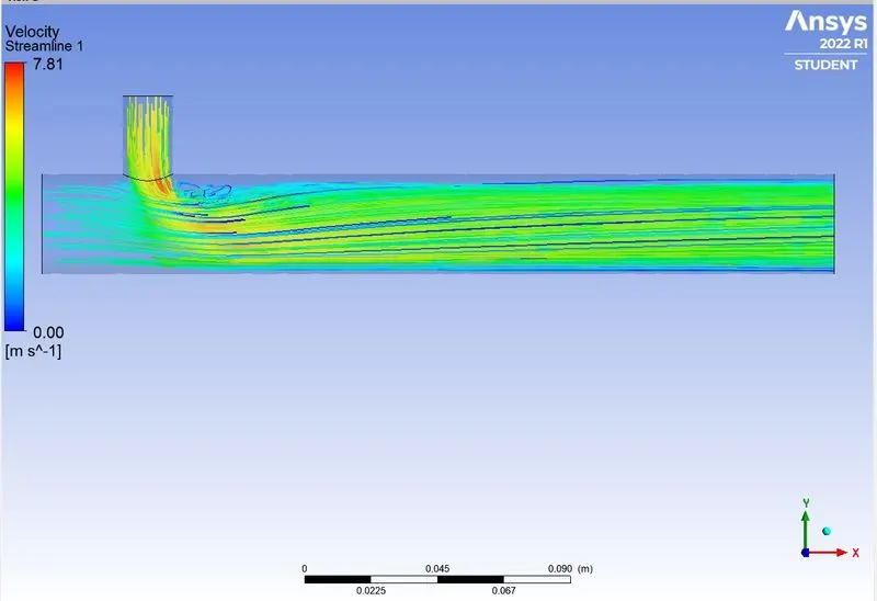
VELOCITY STREAMLINE -
RESULTS FOR (K-OMEGA)-
RESIDUAL PLOT-
AREA WEIGHTED AVERAGE-
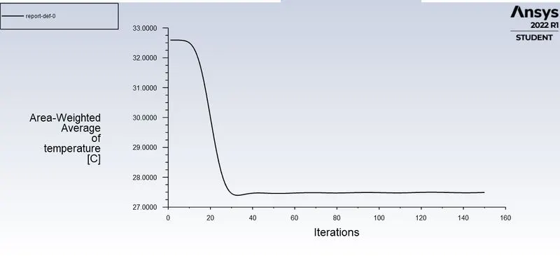
STANDARD DEVIATION-
TEMPRATURE CONTOUR-
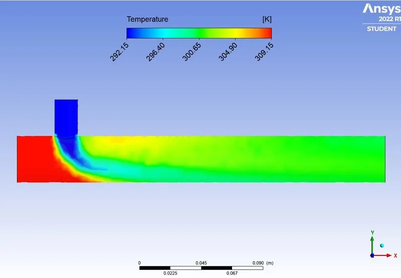
VELOCITY CONTOUR-
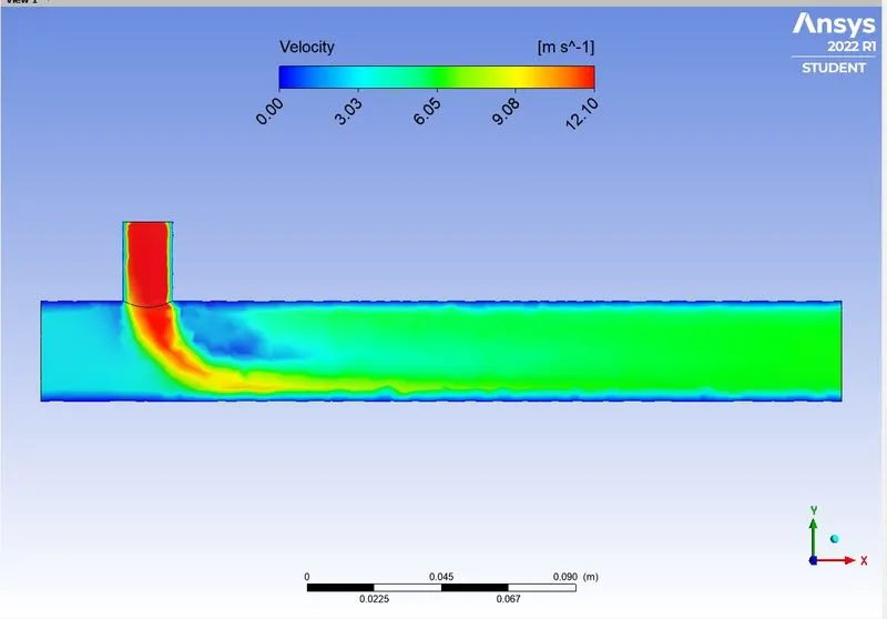
VELOCITY STREMLINE-
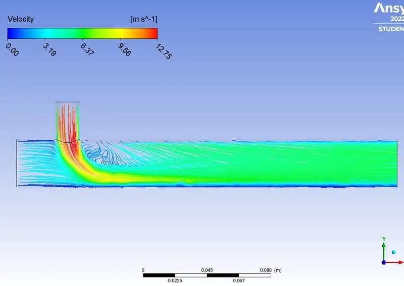
COMPARISION OF BOTH LONG AND SHORT TEE-
-The average outlet on both cases are quite same ,as momentum ratio increses the velocity of cold inlet fluid increses and due to high relative velocity between the fluid expreience higher turbulanc and therefore the outlet fluid temperature decreses.
-In order to obtain better mixing the velocity of cold air is important by increasing the cold fluid velocity the outlet temprature gets reduced.
-Higher the momentum ratio higher will be the mixing efficiency of the tee joint.
-There is table given bellow , which gives better understanding about both the tees.
| GEOMETRY | CELL COUNT | AVG. OUTLET TEMP.(C) | NO. OF ITERATION |
| SHORT TEE | 12583 | 30 | 160 |
| SHORT TEE | 12538 | 27 | 152 |
| LONG TEE | 15360 | 30 | 187 |
| LONG TEE | 15360 | 27 | 153 |