Week 1- Mixing Tee
PROCEDURE AND RESULT:
1.Case1
- Short mixing tee with a hot inlet velocity of 3m/s.
- Momentum ratio of 2,4
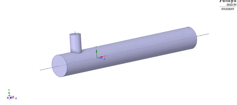
Geometry:
The Geometry has been provoided in the challenge interface The first case is simulated with the short T-joint with the momentum ratio 2.
Meshing:
We have done mesh refinement by an element size=0.002m and keeping the rest of it default
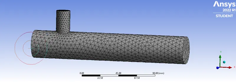
with an element quality of:
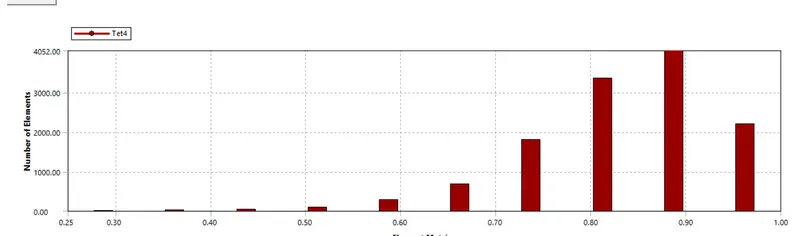
After creatying the Mesh file, we name the geometry for the further use
1.Inlet x(inlet where the hot air come from)
2.Inlet y(inlet where the cold air come from)
3. The walls
4. Outlet
After updating the mesh file we go to the solution part.
Solution
short TEE (MR=4& INlet Hot Velocity=3m/s)
SETUP K-epsilon K-omega
Solver Type Pressure Based Pressure Based
Velocity Formulation Absolute Absolute
Time Steady Steady
Viscous Model Realizable k-epsilon with k-omega SST model
standard wall function
Material Air Air
Cell zones
volume_volume Fluid type:Air Fluid type:Air
Inlet x(velocity inlet) Inlet x(velocity inlet)
Velocity Magnitude 3m/s Velocity Magnitude 3m/s
temperature 36 deg c temperature 36 deg c
Boundaries inlet y(velocity inlet) inlet y (velocity inlet)
velocity magnitude 6m/s velocity magnitude 6m/s
Temperature 19 deg c Temperature 19 deg c
Outlet (pressure outlet) Outlet (pressure outlet)
Gauge Pressure 0 Gauge Pressure 0
walls-Stationary walls walls-Stationary walls
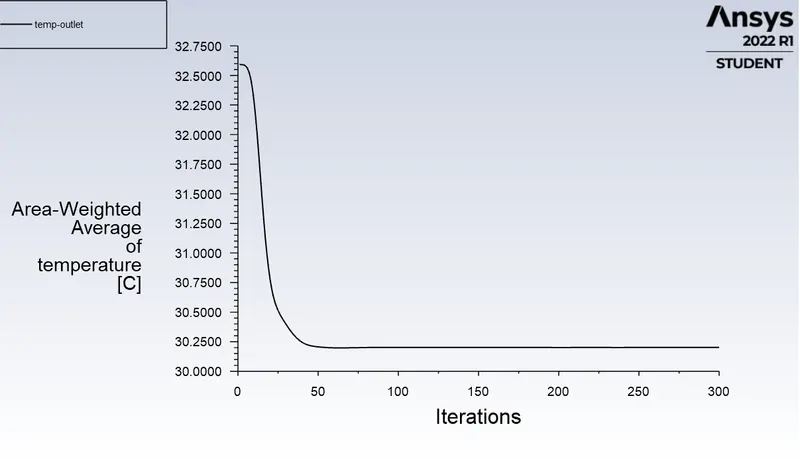
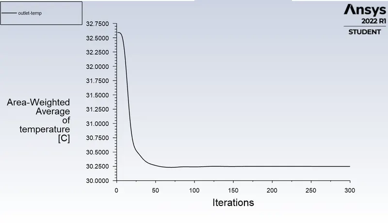
left being k-epsilon and the right being the k-omega
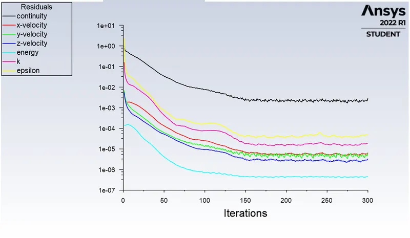
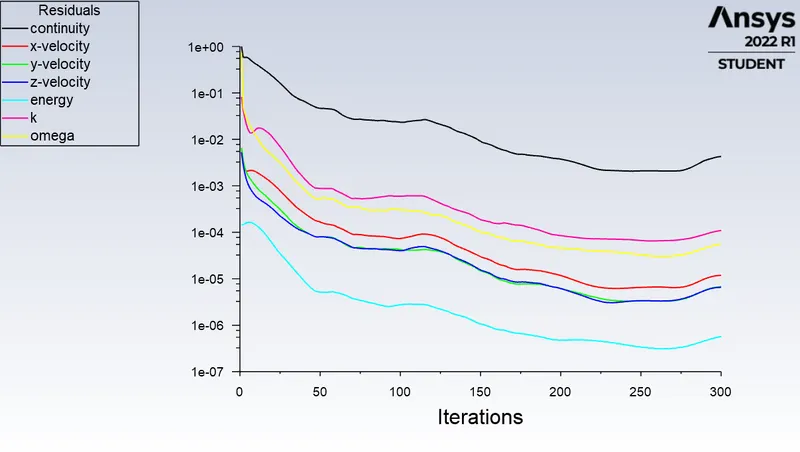
Residual Plot
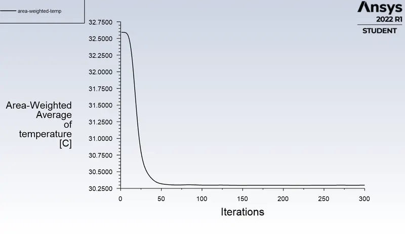
Averageweighted area plot to find the outlet temperature
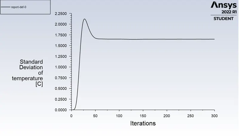
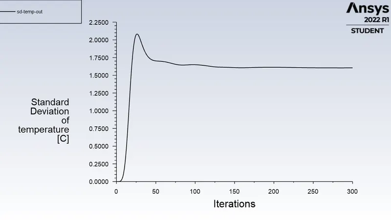
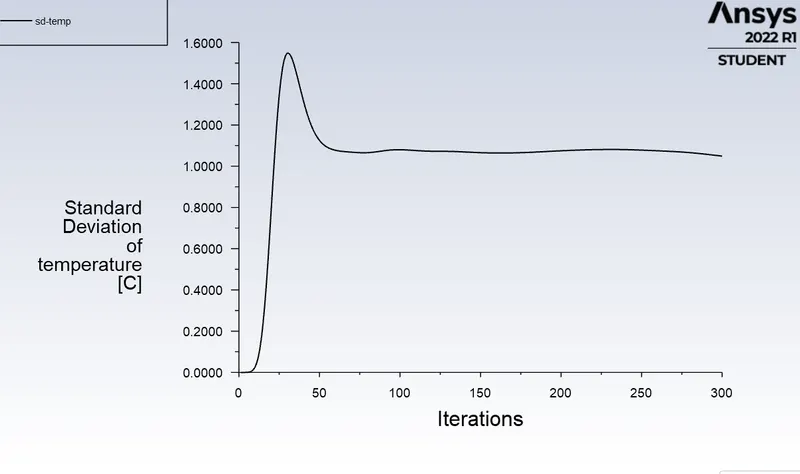
Standard Deviation Plot to find the Effectivness of Mixing at the Outlet
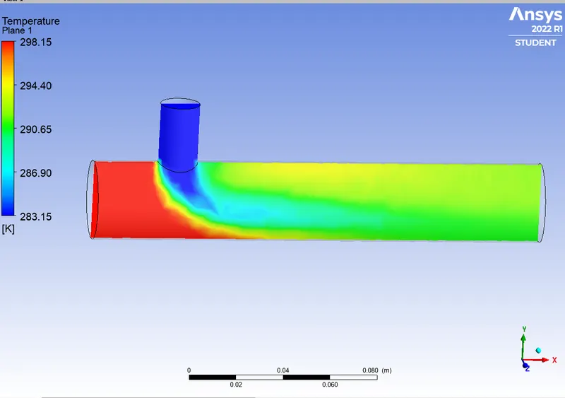
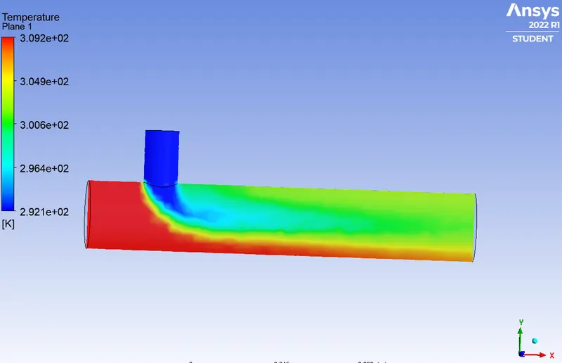
Countor Plot
1) For temperature distribuition
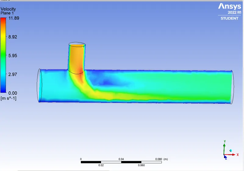
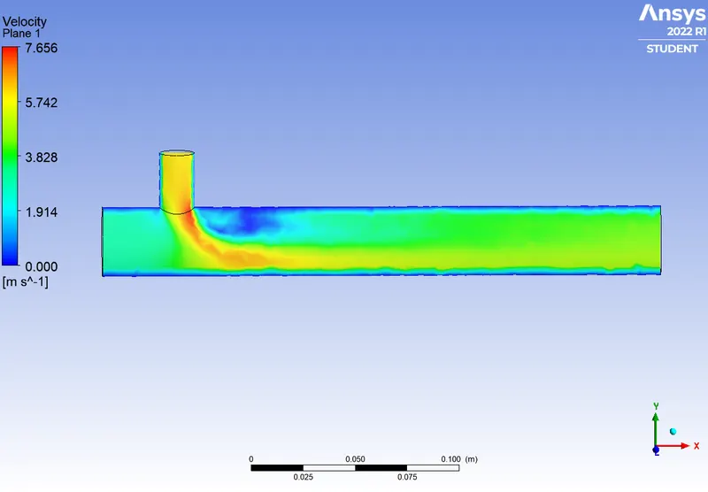
2) For Velocity Distribution
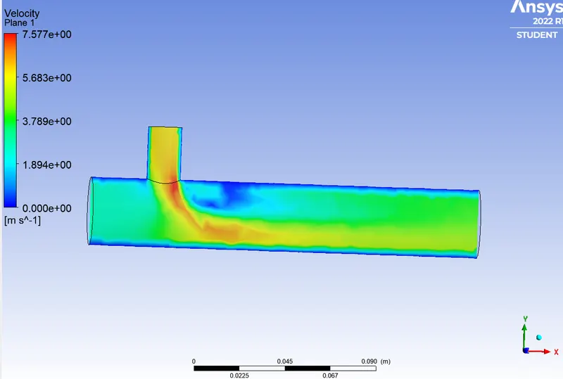
CASE 2:
- Long mixing tee with a hot inlet velocity of 3m/s.
- Momentum ratio of 2,4
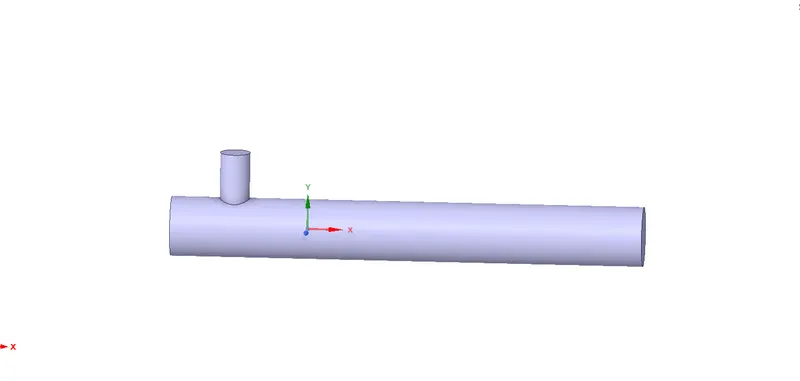
Geometry
The Geometry has been provoided in the challenge interface The first case is simulated with the short T-joint with the momentum ratio 2.
Meshing:
We have done mesh refinement by an element size=0.002m and keeping the rest of it default
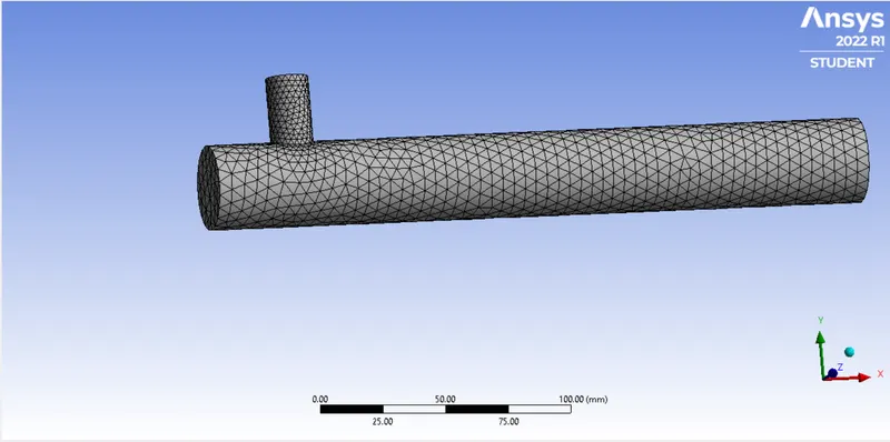
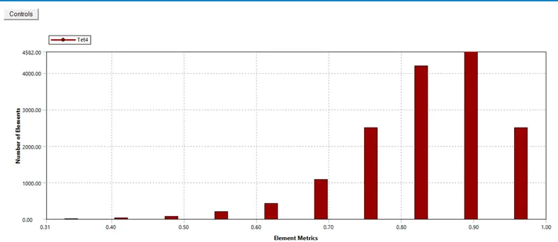
After creatying the Mesh file, we name the geometry for the further use
1.Inlet x(inlet where the hot air come from)
2.Inlet y(inlet where the cold air come from)
3. The walls
4. Outlet
After updating the mesh file we go to the solution part.
Solution
short TEE (MR=4& INlet Hot Velocity=3m/s)
SETUP K-epsilon
Solver Type Pressure Based
Velocity Formulation Absolute
Time Steady
Viscous Model Realizable k-epsilon with standard wall function
Material Air
Cell zones
volume_volume Fluid type:Air
Inlet x(velocity inlet)
Velocity Magnitude 3m/s
temperature 36 deg c
Boundaries inlet y(velocity inlet)
velocity magnitude 6m/s
Temperature 19 deg c
Outlet (pressure outlet)
Gauge Pressure 0
walls-Stationary walls
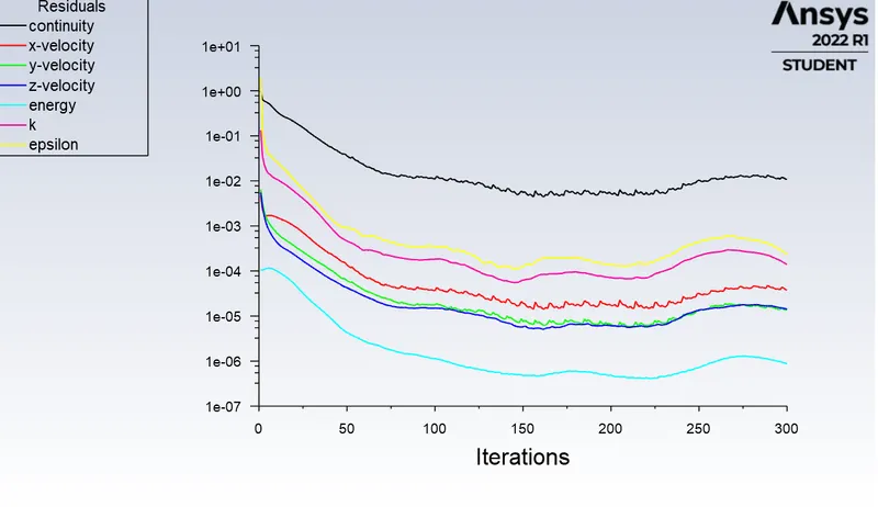
Residual plot:
Average weighted area plot to find out outlet temperature:
standard deviation to find the effective of mixing at the outlet:
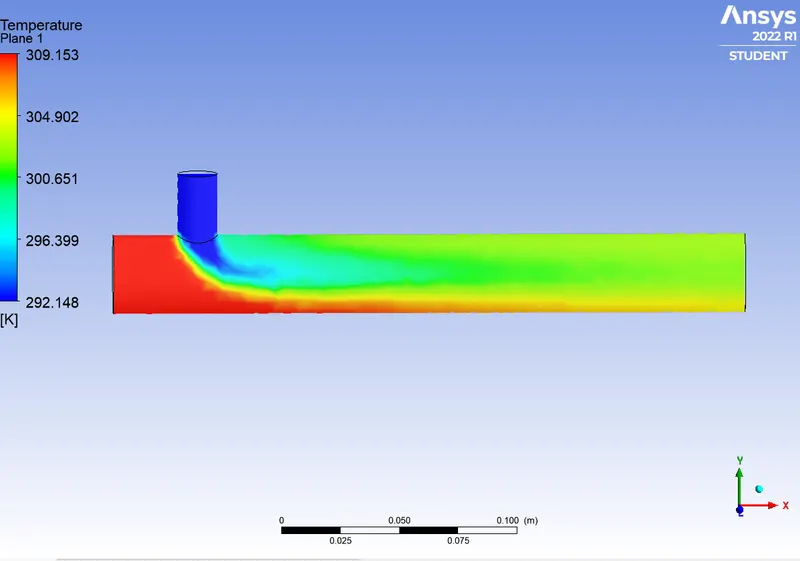
conter plot
1) For temperature distribution:
2) For velocity distribution:
CONCLUSION
• And as the length of the pipe increases the mixing has a lot of time and increases the temperature losing its main objective.
In both cases of K-epsilon snd k-omega, k-epsilon has better results as we see in the residual plot these converge faster compared to k omega
• From the above results, the meshing has to be improved. Which may give better results
• By doubling the chilled air velocity at the inlet results in better outlet mixing temperature which pretty much an acceptable result for us.