Week 1:- Introduction to BiW and Fixtures Challenge
- What is BIW & define its parts?
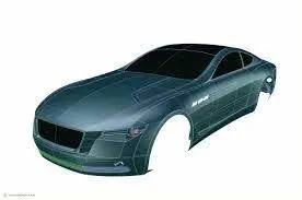
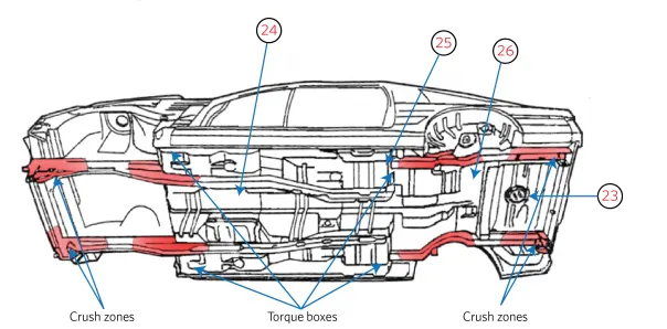
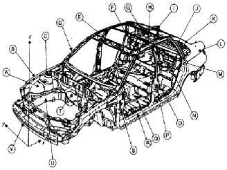
Body in White (Biw) is stage where car body sheet metal components have been welded together to form the vehicle structure. components include the hood , fender ,side doors, roof , back door , floor of vehicle , body side. Biw refers to the stage after all those components are welded together and inserted into an electrolyte chamber to form gray colour coated look which is before to apply paints.
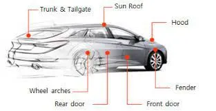
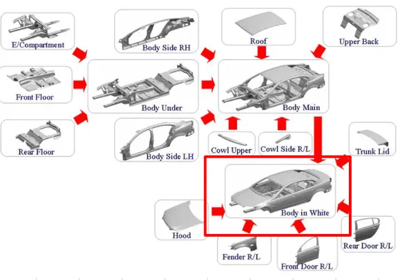
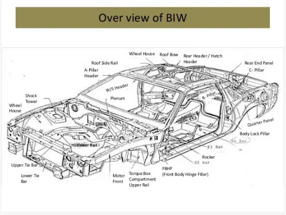
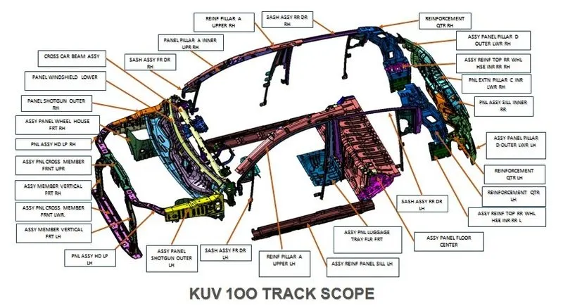
Parts of Biw :
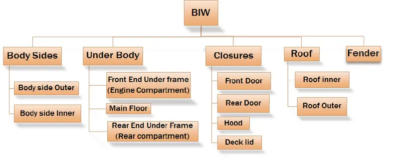
I. Body Side :
1. Body Side Outer
2. Body Side Inner
It refers to the side bodies of the car which is Left body side components and Right body side components. Its helps to mount various components like Drip Area, A -plillar, Side body, Sill, Baffle etc.
II. Under Body :
1. Front End under frame :Portion for Mounting Engine, radiator , battery, Head lights, Mirrors are mounted together to the front portion of the car
2. Main Floor : Portion for Mounting Seats, Steering wheel assembly , Dashboards, AC units
3. Rear End under frame :Portion for Mounting back door , Gas Stays, Hinge assembly , Bumpers etc.
III. Closures
1. Front Door : Front Door on left side and right side
2. Rear Door : Rear Door on left side and right side
3. Deck Lid : To cover interior and boot space.
4. Hood : Covering the front portion of the car above Engine compartment.
IV. Roof
1. Roof Outer : Class A surface which is visible to the customer it should not have any marks .
2. Roof Inner: Inner panel which consists of Front and Roof rails, bow roofs and center roof rail to satisfy the crash and rool over requirements.
V. Fender :
Main function of fender is to prevent the foreign particles (mud, stones , water ) entering inside the passenger compartment.
2. What do you understand by BIW nomenclature?
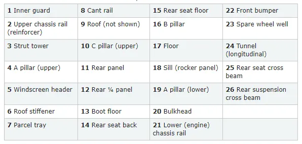
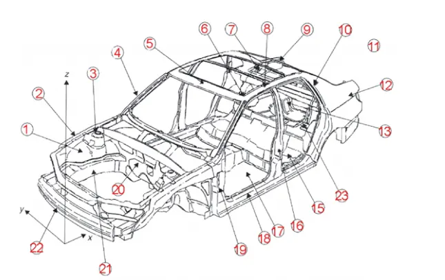
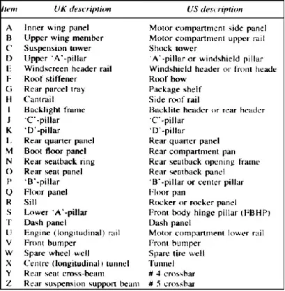
Nomenclature indicates the identification of each and every components in easily by providing unique number or code or name to each and every component in the assembly. Assembly will be there, we are indicating the number to easily track the part and access it quickly without much manpower and consuming lot of time.
3. What is fixture & its types?
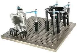
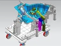
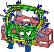
A fixture is a device which holds or support the workpiece during various operations in a assembly line. Fixtures are used to position in a specific location or orientation and support the work, ensuring that all parts produced using the fixture will maintain conformity and interchangeability.
Welding fixtures function is to hold and support the various components that are welded together. It is necessary to support them in a proper location which is capable of preventing deformation and motion of the object during welding.
Types of Fixtures:
Production Fixtures : Used in Assembly line where assembly is going to happen in a cyclic manner or sequence manner operations. Useful for Mass production concept and maintain in regular intervals to avoid the errors in position and orientation. Have more advanced features which will reduce the assembly time and cost.
Pre production operation fixtures: Best Suited for R&D where initial batch production is made to study the feasibility for making the prototype model. Having Basic features to hold the part and perform specific operations (Drilling, boring)
Checking fixtures: Best suited for inspection purposes, hold the parts or assemblies and measure the gaps,flushness and checking the dimensions of the components.
4. What is the basic principle of fixture design?
The 3-2-1 principle of location is used to constrain the movement of workpiece along the three axes XX, YY, and ZZ and how to locate the work piece in the fixture.
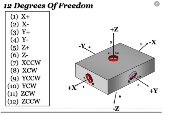
For any free body there are total of twelve degrees of freedom as below:
i. 6 translational degrees of freedom: +X, -X, +Y, -Y, +Z, -Z
ii. 6 rotational degrees of freedom :
Clockwise and Anticlockwise around X axis (CROT-X, ACROT-X )
Clockwise and Anticlockwise around Y axis (CROT-Y, ACROT-Y)
Clockwise and Anticlockwise around Z axis (CROT-Z, ACROT-Z)
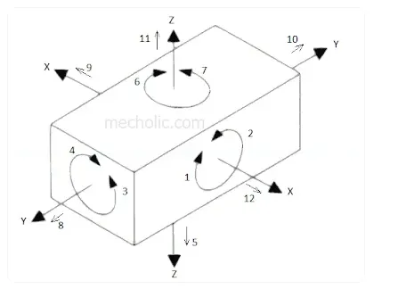
For any parts, 12 degrees of freedom of the workpiece need to be fixed constrian so that the workpart has zero degree of freedom and fixed position when we apply force or perform any operations. .
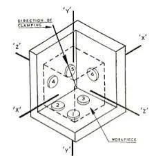
Pins 1,2,3 restricts the x axis rotation in cw and ccw, translation in -y direction and rotation in z axis.
Pin 4 and 5 restricts the y axis rotation in cw and ccw, translation in -z direction.
Pin 6 restricts the translation in -x direction.
so in above example 9 DOF are arrested and remaining 3 dof are free for movement of workiece during loading and unloading process.
5. Elaborate types of BIW Stations?
Biw Stations is the assembly line in which all the parts are assembled together in specific sequential manner.
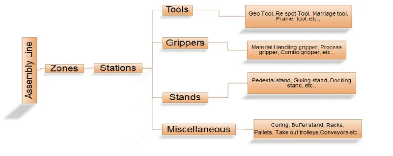
1. Tool Stations:
i. Geo Tool: A geo tool is a fixture in which the geometry of the panels are welded together in the predefined spot. The pin tolerance for a geo pin will be of -0.15 in general.
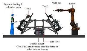
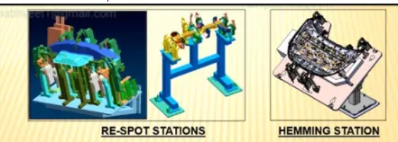
ii. Re-spot Tool: A re-spot tool is a fixture position where the remaining weld spots are welded which excludes the geo tool spots.
iii. Hemming Tool: Its a fixture in which the inner panel and outer panel are joined together by spot welding or by hemming process.
iv. Checking Stations: Tool is a fixture which is used to check the parts or assemblies - ensuring all the coordinates, relative dimensions & positions as per the tolerances. Includes gauge type, fixed type and automated checking fixtures
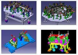
2. Gripper Stations
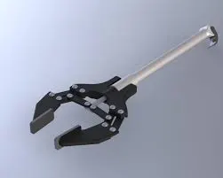
Gripper: A Gripper is a device which holds the panel and is fixed to the manipulating end of a robot.
Types of Grippers:
Material Handling Gripper (MH): Material Handling gripper are designed for moving the components from one Station to other Station.
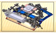
Process Gripper: Process gripper are designed for moving the components from one Station to other Station., additionally it undergoes process like pedestal welding, pedestal riveting, Gluing, sealing, etc.,
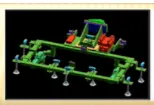
Combo Gripper: Combo gripper are designed for moving the components from one Station to other Station, along with weld gun at another side of the gripper for welding.
Gripper + Weld Gun
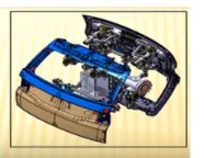
Dual Gripper: Dual gripper are designed for moving the components from one Station to other Station. With two sided gripper.
Gripper + Gripper
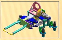
3. Stand Stations
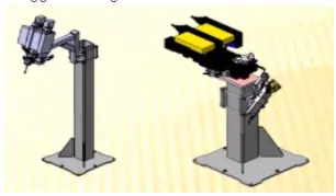
Gluing and sealer stand: Gluing or sealer gun is fixed to a welding station, which is mounted to the floor permanently.
Docking stand: Multi tasking like material handling & welding , which cannot carry more load at the same time.
Date stamp stand: The panel will get the date embossed on to it, date, part number etc.
Pedestal gun stand: Weld gun is mounted to a fixed stand which is mounted to the floor permanently, Where the process gripper carries the part to weld the spot with this fixed welding gun.
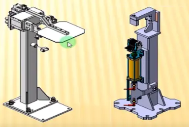
Take out Trolley: Take out trolley is used to take the car panel out inspection purpose once the sub assembly line process is completed.
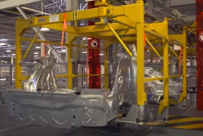
Conveyors : Assembly Line conveyors are used to move the assembly with the help of belt or chains.
6.What are the basic terminologies used in the BIW fixture?
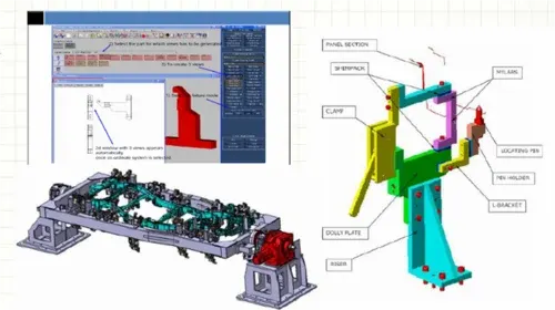
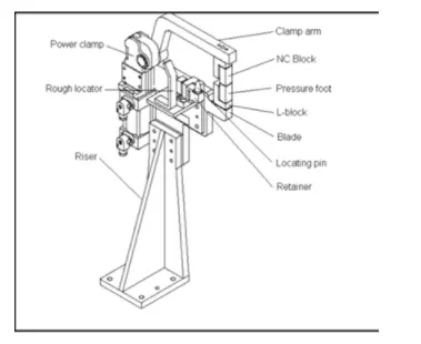
1. NC/ MYLAR :
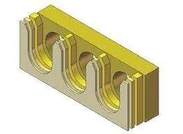
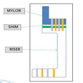
MYLAR is one kind of block that touches the panel and holds or clamps the panel. Resting and Clamping
Points at which the car panels are to be located onto the fixture.
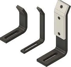
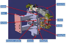
The plate which connects Riser to the Clamp cylinder is named Blade. This plate plays an important role in building the unit. The plate can be of any shape. But we need to keep in mind that the plate should be as compact as possible.
4. RISER :
The part which is mounted on the base plate and holds a clamp or pin cylinder on it, is called Riser. Riser can be Standard Part or manufactured part, it varies from project to project. A riser can be a Single part or welded part. Standard risers also have various shapes and sizes.