Week 1:- Introduction to BiW and Fixtures Challenge
what is biw and define its parts ?
BIW-Body in White
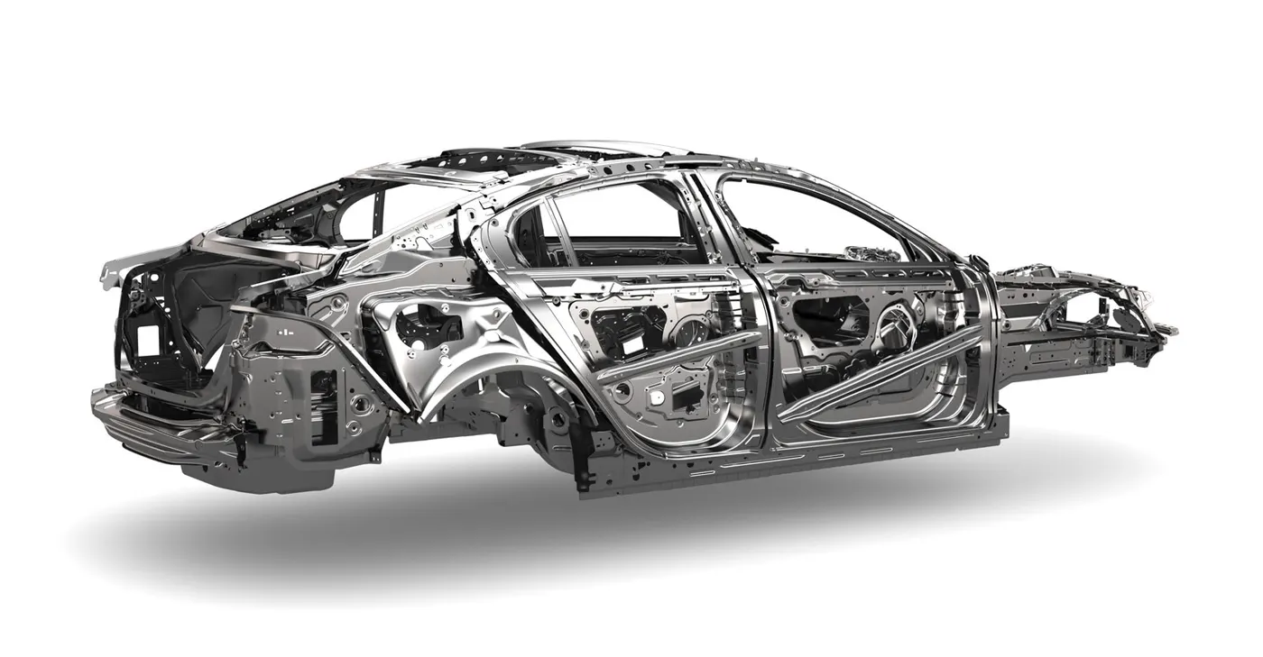
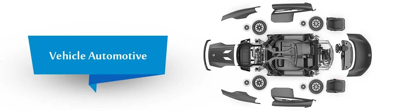
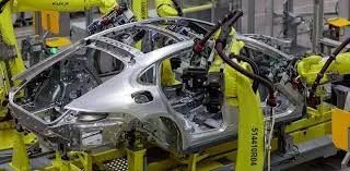
In the Automotive Industry BIW (Body in White) is the common terminology used to mention the car sheet metal welded structure .
In today's situation, automotive BIW is made of steel (various steel grade material -DP, DD, HDP etc.) as well as made of aluminium alloy.
Sub-assemblies like Under body, Body side Left Hand Side/ Right Hand Side, Front End, Roof etc. gets welded together by various metal joining process e.g. resistance spot welding, Laser welding, MIG welding to make welded metal shell (Without Door, Trunk-lid / Tailgate) , Fender, Bonnet Center) called Body in White.
Automotive car shell made before painting is called Body in White
BIW joinery decides the exterior and interior look of any car.
All the Interior Parts(Commonly used in Automotive) e.g. Dashboard, Trim (Door Trim, Pillar Trims, Roof liner, Seats are mounted on the BIW shell with the help of various brackets or nuts mounted on the BIW.
Exterior (Commonly used term in car industry) components e.g. Front Bumper, Rear Bumper, Fender LH/RH, Side Mirrors are mounted on the BIW shell with the help of various brackets or mounting systems.
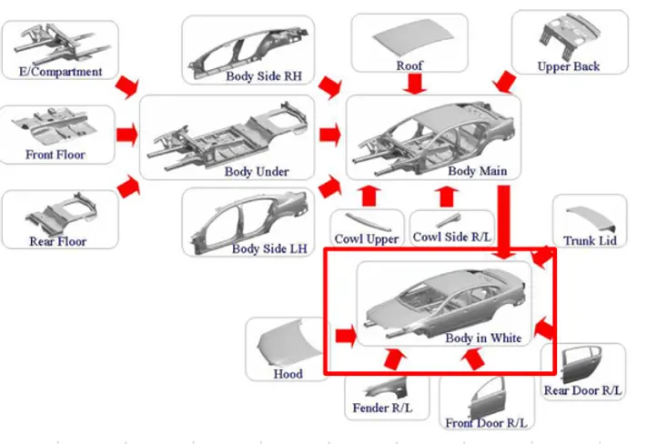
parts of biw
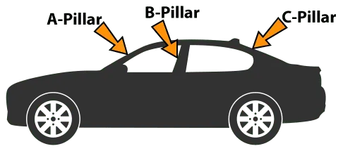
•A,B,C,D Pillars
•Dashboard mounting panel
•Windscreen & Rear Window rail
•Cant rail
•Roof structure
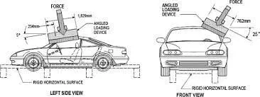
•Side Sill
•Upper quarter panel or window
•Front longitudinal member (acts as chassis)
•Front cross member
•Front & rear Valance
•Scuttle
•Firewall
•Floor, seat & Boot pan
•Front & rear Spring tower
•Central Tunnel
•Front & Rear Wheel arch
•Toe Board
•Heel Board
What do you understand by BIW nomenclature?
1. Automotive Basics:
• Classification, types, assembly and sub-assembly etc.
2. Automotive body Basics:
• Customer expectations, Branding, Specification, Major functions, Ergonomics etc.
• Evolution, Different types of constructions, Benchmarking etc.
• Material – Specifications, Selection, Database search, manufacturing processes etc.
3. NPI & Auto BIW Development
• Overview of Vehicle design program, Interior designing milestones, role and responsibilities of team.
• Interior BOM, Subsystems & Part nomenclature.
• Design Process for complex depression, flange, beads, dart, & bow Packaging data, Kinematics, Costing, Fit and Finish.
4. DFM, DFA, DFMEA, Quality Standards, DFR
5. Manufacturing Processes
• Die designing
• Tooling
6. CAD, GD&T (3DCS, CETOL tolerance analysis)
• Model Preparation from IGES, from Class A surface, Missing surface & Draft.
• CAE analysis for strength and stiffness
7. Six Sigma (Theory & application)
• DMAIC (Define, Measure, Analyze, Improve, Control) Six Sigma Program
• Design for Six Sigma (DFSS)
8. VA/VE, & PLM Overview
9. Soft skills, Employability enhancement
• Communication skills, Time Mgt, Project Mgt, Quality Standards, MS office, Interview Skills, etc.
What is fixture & its types?
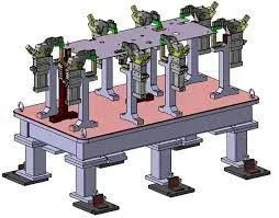
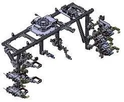
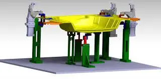
- Welding fixture designing for complete Body shell (Side body, under body, Enclosures etc.)
- Designing of prototype and series production welding fixtures.
- Designing of Geo and Respot welding stations.
- Side body framing station.
- Checking and Setting fixtures.
- Hemming fixtures.
- Weld Gun foul analysis.
- Robotic Grippers.
- 3D Concept designing, 2D drafting, detailing and Bill of material generating.
- Simple equipment for pure assembly purposes and equipment for process confirmation.
- Shuttle system and conveyors.
What is the basic principle of fixture design?
Basic principles of Jigs and Fixtures design
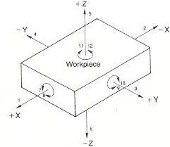
LOCATING POINTS: Locating the work is a prime necessity and requires suitable facilities. The correct setup ensures smooth insertion of a workpiece in the proper position and removing a workpiece from a jig without operational hassles or time consumption. The workpiece position needs to be precise with the guiding tool in the jig or setup pieces in the fixture.
FOOLPROOF: A foolproof design of jigs and fixtures does not permit a tool or workpiece to be placed in any other way other than the intended one.
REDUCTION OF IDLE TIME: Jigs and Fixtures must be designed in such a way that ensures smooth loading, clamping, machining, and unloading of a
WEIGHT OF JIGS AND FIXTURES: A jig and fixture must be compact, easy to handle, and low cost regarding the number of materials used without giving up stiffness and rigidity.
JIGS PROVIDED WITH FEET: Some jigs require feet so that they can be placed on the table firmly.
MATERIALS FOR JIGS AND FIXTURES: Jigs and Fixtures are usually created with hardened materials to resist wear & tear and avoid frequent damage—for example, Mild steel, Cast iron, Die steel, High-speed steel, Caesium.
CLAMPING DEVICE: A suitable clamp is rated for its strength. It should be able to hold a workpiece firmly in its position while bearing the strain of the cutting tool simultaneously, without springing.
Elaborate types of BIW Stations?
1. Geo station:
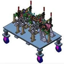
In this station geometry of two parts are fixed. it can be either using welding or riveting . In this station precision and geomatry of the finished product is defined Locating pins have closer tolerence of 0/-0.15.Suppose the hole dia of panel is 16mm then the pin dia minimum can be 15.85. Diameter of locating pins should be lesser than the panel hole dia. So Tolrence in locating pin is given in negative value.
2. Respot Station :
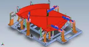
Once product comes out of the Geo Station and there are left out spots where spot welding or riveting is to be done. then it is moved to another station , that station is called Re-spot station.These left out spots may be the due to clamp plan, cycle time,robot reach ability or any other various reasons.In this station pins ahve tolrence upto 0/-0.28.
3. Pedestal Station :
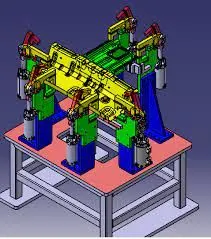
In this station , Pedestal gun is mounted on a tool and panel is manipulated manually or by robot to weld the panels.Pedestal station is generally a Re spot station.Re spot station and Pedestal station, both perform same kind of operation . but to decide whether to go for pedestal or a re-spot station some parameters needs to consider like cycle time, floor space, no. of welds, clamp plan, or size of the panel.
4. Loading Station :
This station is used for loading of panel and same station is used to change the orientation of the if it is required in the upcomin station.Sometime this station is used when Robots are unable to transfer panel from one station to another
5. Buffer Station :
This station is used to make the balance between the process.Some stations carry out procees in lesser time as compared to their respective stations.In that case panels can be stored in one sation so that assembly line process remains smooth.
6. Marriage Station :
In this Station inner and outer panels are joined. In this station to avoid the imprssion on the outer panel(A class surface), copper strips are used in betweenn the weld tip and A-class surface.
What are the basic terminologies used in the BIW fixture?
MYLAR :
MYLAR is one kind of block that touches the panel and holds or clamps the panel. Mylars are always designed in CAR LINE. Mylar is also called NC(Numerically Controlled)Block. Mylars are mounted on any block or plate with Shimming, So that height of mylar can be adjusted accordingly at the assembly level. For ‘A’ class surfaces Nylon mylars are used. So that surface can be saved from scratches.
Shimming can be 1 directional, 2 directional, or 3 directional as per the NC cut.
PIN:
Pins are used to locking the rotational movement of the panel. Generally there two types of Pins, one is Round Pin and another one is a Diamond pin. We use two and three-directional shimming for pins as per the angle of the pin w.r.t. the carline. In some cases, we use a collared pin, when the pin is supposed to support the panel as well. For this kind of pin, we provide 3 way shimming irrespective of pin angle to the carline.
BLADE :
The plate which connects Riser to the Clamp cylinder is named Blade. This plate plays an important role in building the unit. The plate can be of any shape. But we need to keep in mind that the plate should be as compact as possible.
L BLOCK :
A plate shaped as L is called an L block. This part is used as a connection between mylar and Blade. Generally, L blocks are used to provide shimming. It is not necessary that L blocks are only used for shimming, its uses changes as per the requirements, At some places, it is used just to connect one part to another. Similar to the L block one more block is used which is in the shape of T. So this block is called a T Block.
PIN BLOCK :
Pin Block is also called Pin Retainer. This block holds the pin and restricts the rotational motion of the pin. Pin Block can be either manufactured one or Standard.
RISER :
The part which is mounted on the base plate and holds a clamp or pin cylinder on it, is called Riser. Riser can be Standard Part or manufactured part, it varies from project to project. A riser can be a Single part or welded part. Standard risers also have various shapes and sizes.
WELDMENT :
Weldment is the assembly of two or more parts that are joined by welding. To make a weldment it is the thumb rule to have a 5 mm overlay on each other plates so that space can be provided for welding. A weldment can be of any size and any number of plates.