Week 1:- Introduction to BiW and Fixtures Challenge
What is BIW?
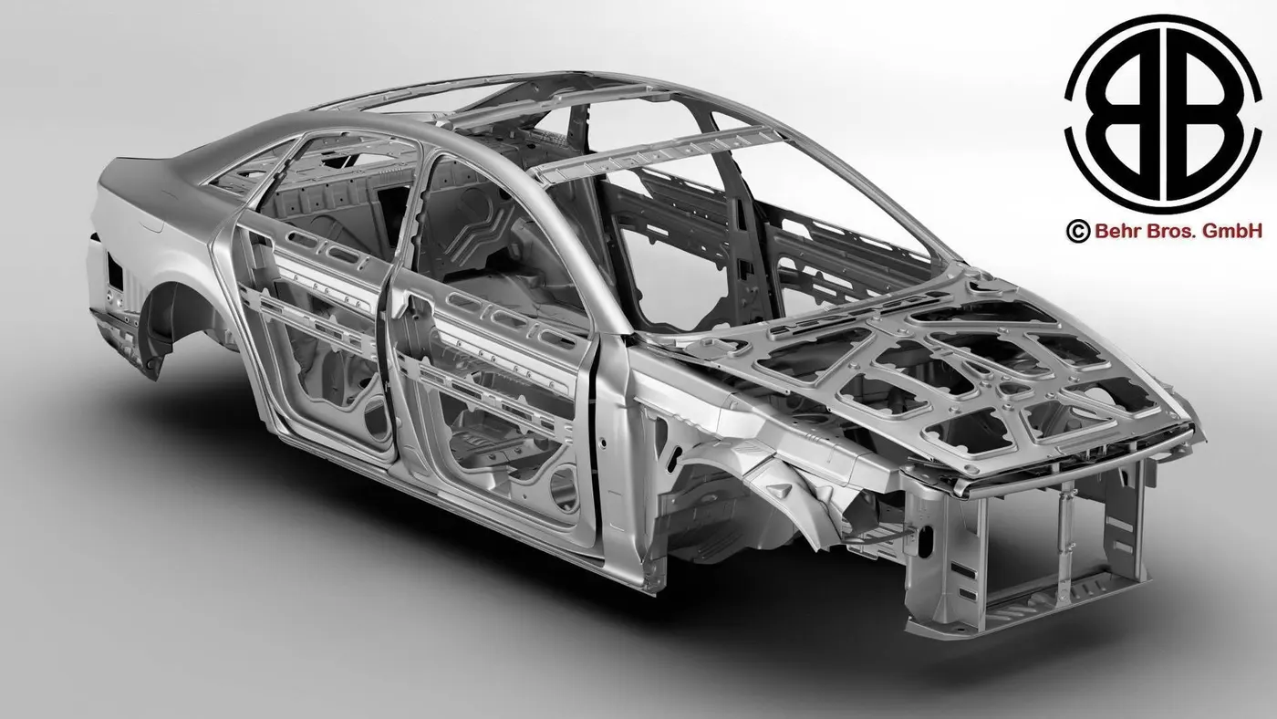
Body in white (BIW) signifies the phase in automotive production where the components of a car body are assembled using various methods such as welding (spot, MIG/MAG), riveting, clinching, bonding, laser brazing, or a combination of these techniques.
Parts of BIW
- Body side
- Body side outer
- Body side inner
- Under body
- Front end under frame
- Main floor
- Rear end under frame
- Closures
- Front doors
- Rear doors
- Hood
- Trunk
- Roof
- Roof inner
- Roof Outer
- Fender
- Reinforcements
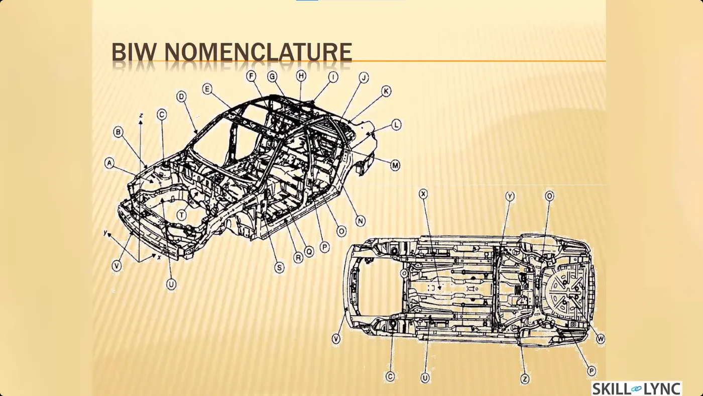
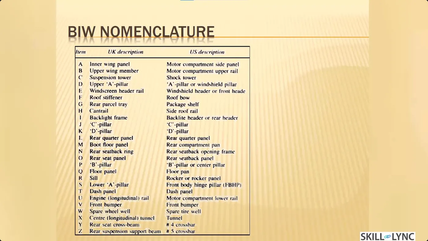
BIW Nomenclature
In the context of Body in White (BIW), nomenclature entails the process of naming each component of the car body. These names serve as subdivisions under the previously categorized parts. While there may be minor differences in nomenclature across regions, the fundamental principle remains unchanged: naming individual sheet metal components within the automotive framework.
Fixtures
A fixture is the device which holds the work piece to be processed (welded) by using 3-2-1 principle. In BIW fixture, the fixtures are designed to hold no. of parts during welding. It is necessary to hold the parts at proper location to avoid the distortions & to maintain the required geometry of the parts.
BIW fixture requirements
- It should prevent distortions in work piece during welding operation
- The clamping need to be light but firm means the clamping force should be able to maintain the part at its required position without damaging the part.
- Placement of clamping need to be clear of welding area.
- Fixture need to be quite stable & rigid to withstand the welding stresses.
- The fixture should maintain its consistancy to do defect free operations.
Types of Fixtures
- Production fixture
- These fixtures are used for mass production. Since these fixtures are used for mass production, they should be simple, rigid and hard. These fixtures should be periodically maintained in regular intervals to avoid errors and repairs. The design of the fixture should be in such a way that it should be easy to load and unload the workpiece within seconds to increase the productivity of the processing/assembly.
- Pre production operation fixture
- These fixtures are basically newly designed fixtures for the new products or parts. These may be complex, manual and heavy based on the application. These can be referred as the protype fixtures. Once the preproduction operation fixture functions properly, then modifications are made to improve and to make it simple and reliable. These fixtures are used in special cases or during initial or trail stages of processing/production
- Checking fixture
- These fixtures are used for checking and inspection purpose. No processing is done in these fixtures. These fixtures consist of gauges for checking the dimensions and tolerances and its accuracies. In some checking fixtures, fixtures are fixed and CMM devices check the geometrical accuracies.
Basic principle of Fixtures
The principle used is 3-2-1 principle. It resists all degrees of freedom of the working piece
The DOF are
6 translational degrees of freedom: +X, -X, +Y, -Y, +Z, -Z
6 Rotational degrees of freedom are
Clockwise around X axis (CROT-X)
Anticlockwise around X axis (ACROT-X)
Clockwise around Y axis (CROT-Y)
Anticlockwise around Y axis (ACROT-Y)
Clockwise around Z axis (CROT-Z)
Anticlockwise around Z axis (ACROT-Z)
BIW Stations
BIW Station is the part of BIW assembly line. The BIW assembly line is divided into zones & these zones are again divided into stations.
The BIW stations are further divided into following
- Tool stations
- Geo Fixtures
- Re-spot Fixtures
- Marriage Fixture
- Framer Fixture
- Checking Fixture
- Gripper stations
- Material handling gripper
- Process grippers
- Combo Gripper
- Dual Gripper
- Stand station
- Pedestal stands
- Gluing & sealer stand
- Docking stand
- Date stamp stand
- Miscellaneous stations
- Curing
- Buffer stand
- Take out trolleys
- Conveyor
BIW Terminologies
- NC/Mylars/Fingers
- Mylars are the component that holds the panel while These are placed from topside & from the bottom side also. The top side Mylars called Clamping Mylars & the bottom side Mylars called Resting Mylars. Every clamping Mylars have resting Mylars. It doesn't allow deformation of the part due to welding stresses
- Principle locating point (PLP)
- These are the points that are used for the accurate location of the part to maintain the geometry of the part. There is lots of holes on the panel which are not accurate due to stamping operation. The PLP are defined in the drawing. The positional dimensions or relative dimensions are very precise in stamping & in fixtures also.
- Risers
- Risers are of different types like L-typer rises, Square tube riser Riser is the manufacturing part which gives height to the assemblies.
- Blade
- Blades are plates mounted on the riser. Other parts like cylinder, arms etc are mounted on the blade.
- Shims
- Shims are the small part which comes with the thickness of 0.1mm, 0.2mm, 0.5mm etc. These will compensate the stackup tolerance which reflects at the panel holding part called Mylars. We give tolerance to all the parts of the fixture. Due to this tolerance the Mylars will either lift up or goes down from its defined position. If the Mylars goes down from the defined height it will make impression or dent on the panel. If the Mylars lift up then there will be a distorsion due to welding stress. To adjust the Mylars At its defined position we use shims so the panel won't deformed & also dont get any impression on it.
- Rough locators
- The operator can place the part in the wrong orientation The rough locator will work as a guide while placing the part in the fixture & the part will be loaded in the desired orientation.
- Hardwares
- Hardware is like the Hex head bolts, Allen Bolts, Hex nuts, Spring washers, Self-locking nuts
- CMM
- CMM stands for coordinate measuring machine. It is a device that measures the geometry of physical objects by sensing discrete points on the surface of the object with a probe. It generates a report by comparing the data with the CAD file data.
- Unit
- The fixture is the assembly of different types of units to form a part. There are different units like pin unit, base unit, clamping unit, etc.
- Number plates
- The number plate is the aluminum embossed plate placed on each unit for easily recognizing the part unit.
- Name plate
- The data like manufacturing company name, fixture type, Fixture weight is embossed on the plate & joined to the fixture.
- Clamp Arm
- The clamp arm is the part of the clamp unit which moves an Over clamp arm the Mylars are mounted.
- Pivot
- It is an axis about which the clamp arm will rotate
- Class A Surface/Skin surface
- The outer panels of the car like a hood, door, backdoor, fender, roof are visible to the customer.
- The outer panels should be aesthetically very good. No scratches or dent is acceptable over it.
- While designing the fixture to the skin surface the clamping material should be soft, so that it could not able to left any impression or dent over the skin. generally, nylon or PU material is used for clamping purposes.
- Reed switches & sensors
- These are the electric componnents used in automated fixtures. The reed switch is an electrical switch operated by an applied magnetic field. These detects whether the panel is loaded or not and is done by sensors.