Week 1:- Introduction to BiW and Fixtures Challenge
1.BIW
Body in white (BIW) refers to the stage in the automobile manufacturing in which a car body’s components have been joined together, using one or a combination of different techniques: welding (spot, MIG/MAG), riveting, clinching, bonding, laser brazing etc.
Body in White, or BIW, is a stage in the production of automobiles in which all sheet metal components such as the roof, body side, under body, backdoor, cross members, and other components are welded together and the resulting body is dipped in a primer solution, which has a greyish colour and thus gives the body its name. The car's shape is determined by the BIW, which is obtained after welding and before painting.
BIW is mainly categorized as:
- Body side -
- outer & inner
It generally refers to both the sides of the car that is left and right side. It mounts various BIW components like A-pillar, B-pillar, C-pillar, Panel side sill etc.
- Under body -
- Front end under frame: This is the compartment are where the engine and other components of automobile like battery, radiator etc mounts.
- Main floor: This is the compartment where the interior parts like seats; infotainment panel etc will be mounted.
- Rear end under frame: This compartment shapes the rear end of the car. This is what provides space of mounting of rear closure parts and boot space.
- Closures -
- Front door: Two front doors on each side.
- Rear door: Two rear doors on each side.
- Hood: To cover the engine compartment.
- Trunk lid: To cover the interior and boot space
- Roof -
- Roof inner
- Roof outer
- Fender - The component seats between side body and front end under frame
- Reinforcements
2.BIW nomenclature
The nomenclature differs a little bit from region to region but the overall idea is to name individual automotive sheet metal components.
3.Fixture
It is a holding device which holds the workpiece to be processed. In general fixtures are designed using 3-2-1 principle.
Types of fixture:
- Production fixture
These fixtures are used for mass production. Since these fixtures are used for mass production, they should be simple, rigid and hard. These fixtures should be periodically maintained in regular intervals to avoid errors and repairs. The design of the fixture should be in such a way that it should be easy to load and unload the workpiece within seconds to increase the productivity of the processing/assembly.
- Pre production operation fixture
These fixtures are basically newly designed fixtures for the new products or parts. These may be complex, manual and heavy based on the application. These can be referred as the protype fixtures. Once the preproduction operation fixture functions properly, then modifications are made to improve and to make it simple and reliable. These fixtures are used in special cases or during initial or trail stages of processing/production
- Checking fixture
These fixtures are used for checking and inspection purpose. No processing is done in these fixtures. These fixtures consist of gauges for checking the dimensions and tolerances and its accuracies. In some checking fixtures, fixtures are fixed and CMM devices check the geometrical accuracies.
4.Principle of fixture design
A work-piece free in space can move in an infinite number of direction. For analysis, this motion can be broken down into 12 directional movements or "degrees of freedom". All 12 degrees of freedom must be restricted to ensure proper referencing of a work-piece.
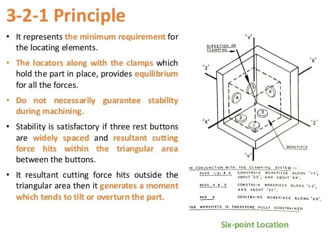
LOCATING POINTS: Locating the work is a prime necessity and requires suitable facilities. The correct setup ensures smooth insertion of a workpiece in the proper position and removing a workpiece from a jig without operational hassles or time consumption. The workpiece position needs to be precise with the guiding tool in the jig or setup pieces in the fixture.
FOOLPROOF: A foolproof design of jigs and fixtures does not permit a tool or workpiece to be placed in any other way other than the intended one.
REDUCTION OF IDLE TIME: Jigs and Fixtures must be designed in such a way that ensures smooth loading, clamping, machining, and unloading of a
WEIGHT OF JIGS AND FIXTURES: A jig and fixture must be compact, easy to handle, and low cost regarding the number of materials used without giving up stiffness and rigidity.
JIGS PROVIDED WITH FEET: Some jigs require feet so that they can be placed on the table firmly.
MATERIALS FOR JIGS AND FIXTURES: Jigs and Fixtures are usually created with hardened materials to resist wear & tear and avoid frequent damage—for example, Mild steel, Cast iron, Die steel, High-speed steel, Caesium.
CLAMPING DEVICE: A suitable clamp is rated for its strength. It should be able to hold a workpiece firmly in its position while bearing the strain of the cutting tool simultaneously, without springing.
5.BIW Stations
The BIW assembly line is where different types of panels are joined together in each specified zone like Underbody zone, Hood zone Etc.
These zones are further subdivided into stations, where various processes like welding gluing and inspection are done to the part of that particular zone before they are being assembled together. For instance, in the roof zone, various reinforcement is to be added before they are married to the side zone.
Geo Tool:
- A geo tool is a fixture in which the geometry of the panel which is welded together is defined accurately.
- In geo fixture two panels will be loaded and welded together.
- Pin tolerance for geo fixture is about -0.15mm.
Re-spot Tool:
- A re-spot tool is a fixture where already welded panels are brought to be welded further.
- For example, on a certain panel we needed to have 50 weld but due to assembly line constrains we managed to achieve 30 on geo tool, then the remaining 20 will be achieved on the re-spot tool.
- Pin tolerance for the re-spot tool is -0.28mm.
Marriage or hemming tool:
- Marriage or hemming tool is a fixture in which the inner panel and outer panel is joined together.
- Hemming is not done for every part but only for those parts where we want to join two panels without other joining process as it may affect the aesthetics of the car.
- Hemming can be found on Hood, Back door etc.
Checking stations:
It is used to check the automotive part or assembly to ensure all the coordinated, relative dimensions and positions are as per tolerance. It can be classified as follows:
- Gauge type checking fixture is where the work piece is held and various gauges are introduced to ensure the dimensions and repeatability.
- Fixed type checking fixture is where the work piece is fixed using clamps and pins and the Coordinate Measuring Machine is used to measure the coordinates of different points of the panel and compare it with the nominal value and give its report to rectify any errors.
- Automated checking fixture is where the automated setting are being done through sensors, PLCs, switches etc, to give a signal in case of any irregularities which can be rectified. As it is expensive, it is not widely used.
Grippers Stations
A gripper is a device that enables the holding of an object to be manipulated. The easier way to describe a gripper is to think of the human hand. Just like a hand, a gripper enables the holding, tightening, handling, and releasing of an object. A gripper is just one component of an automated system. A gripper can be attached to a robot or it can be part of a fixed automation system.
Different grippers are used in BIW as follows,
- A) Material handling gripper
- As the name suggests These grippers are used for material
- These grippers can pick assembly from one station & will drop the assembly at another
B)Process grippers
- These grippers are used to carry out some specific processes like gluing, welding, riveting in addition to material handling.
- The gripper will go under gluing stand in case of gluing process & will goes under the pedestal weld stand in case of the welding process.
C)Combo Gripper
- Combo grippers are the ones which can carry out multiple tasks like it can do material handling & also it can carry out some specific process like gluing, welding as well.
- Weld gun + Gripper
D) Dual Gripper
- These are two-sided In case when we want one LH & one RH part, these grippers are used. It can handle the material from one station to another station
- Gripper + Gripper
3) Stands Stations
Stands are used to hold the part when not in use or also it is used to mount some parts or bodies on it.
Different stands are used in BIW
A) Pedestal stands
- Weld gun is mounted on the fixed stand which is mounted to the floor The gripper can carry the panel under the stand to do the operation.
B) Gluing & sealer stand
- Gluing gun or sealer gun is fixed to a welded or a standard stand which is grouted to the floor
C) Docking stand
- The robots have some limitations such as the payload capacity of the robot & also due to lack of
- When we select the robot for multitasking it can't do both the task simultaneously due to
- In this kind of case, we add a docking stand to put some equipment that is not in use for the current operation but will be required for next
- Hence the robot can drop a gripper or gun & pick the next operation equipment to complete the task from the docking
D) Date stamp stand
- Every manufactured product has some data to stamped or to be embossed on it like serial no, batch no, Date for some future reference, or for data collection.
- The required data is stamped or embossed by using the stamping device mounted
6.Basic terminologies
A) Mylars
Mylars are the component that holds the panel while These are placed from topside & from the bottom side also. The top side Mylars called Clamping Mylars & the bottom side Mylars called Resting Mylars. Every clamping Mylars have resting Mylars. It doesn't allow deformation of the part due to welding stresses.
B) Principle locating point (PLP)
These are the points that are used for the accurate location of the part to maintain the geometry of the part. There is lots of holes on the panel which are not accurate due to stamping operation. The PLP are defined in the drawing. The positional dimensions or relative dimensions are very precise in stamping & in fixtures also.
C) Risers
Risers are of different types like L-typer rises, Square tube riser Riser is the manufacturing part which gives height to the assemblies.
D) Blade
Blades are plates mounted on the Other parts like cylinder, arms, etc are mounted on the blade.
E) Shims
Shims are the small part that comes with the thickness of 0.1mm, 0.2mm, 0.5mm, etc. These will compensate for the stackup tolerance which reflects at the panel holding part called We give tolerance to all the parts of the fixture. Due to this tolerance, the Mylars will either lift up or goes down from their defined position.
If the Mylars go down from the defined height it will make an impression or dent on the panel.
If the Mylars lift up then there will be a distorsion due to welding stress. To adjust the Mylars At its defined position we use shims so the panel won't be deformed & also don't get any impression on it.
F) Rough locators
The operator can place the part in the wrong orientation The rough locator will work as a guide while placing the part in the fixture & the part will be loaded in the desired orientation. It is a part of foolproofing.
G) Hardware
Hardware is like the Hex head bolts, Allen Bolts, Hex nuts, Spring washers, Self-locking nuts
H) CMM
CMM stands for coordinate measuring machine. It is a device that measures the geometry of physical objects by sensing discrete points on the surface of the object with a probe. It generates a report by comparing the data with the CAD file data.
I) Unit
The fixture is the assembly of different types of units to form a part. There are different units like pin unit, base unit, clamping unit, etc.
J) Number plates
The number plate is the aluminum embossed plate placed on each unit for easily recognizing the part unit.
K) Name plate
The data like manufacturing company name, fixture type, Fixture weight is embossed on the plate & joined to the fixture.
L) Clamp Arm
The clamp arm is the part of the clamp unit which moves an Over clamp arm the Mylars are mounted.
M) Pivot
It is an axis about which the clamp arm will rotate
N) Class A Surface
The outer panels of the car like a hood, door, backdoor, fender, roof are visible to the customer.
The outer panels should be aesthetically very good. No scratches or dent is acceptable over it.
While designing the fixture to the skin surface the clamping material should be soft, so that it could not able to left any impression or dent over the skin. generally, nylon or PU material is used for clamping purposes.