Week 1:- Introduction to BiW and Fixtures Challenge
- What is BIW & and what are its parts?
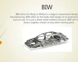
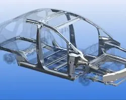
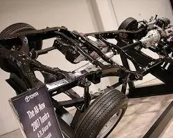
BIW stands for Body in White. It is the main body structure of a car, made of sheet metal. It is the foundation of the car and provides the structural support for the rest of the vehicle. The BIW is typically assembled in a series of steps, starting with the welding of the major components together. Once the BIW is assembled, it is then painted and trimmed.
The main parts of a BIW are:
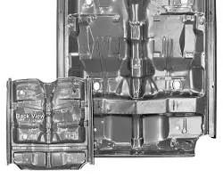
- Floorpan: The floorpan is the base of the BIW and it supports the entire car. It is made of sheet metal and is typically stamped out of a single piece.
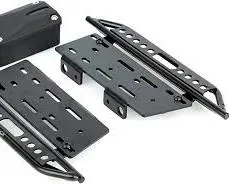
- Side rails: The side rails are the vertical members of the BIW and they provide structural support for the car. They are made of sheet metal and are typically welded to the floor.
- Doors: The doors are the openings in the BIW that allow passengers to enter and exit the car. They are made of sheet metal and are typically welded to the side rails.
- Hood: The hood is the opening in the BIW that allows access to the engine. It is made of sheet metal and is typically hinged to the front of the car.
- Trunk lid: The trunk lid is the opening in the BIW that allows access to the trunk. It is made of sheet metal and is typically hinged to the rear of the car.
- Bumpers: The bumpers are the parts of the BIW that protect the car from damage in a collision. They are made of plastic or metal and are typically attached to the front and rear of the car.
- Suspension components: The suspension components are the parts of the BIW that connect the wheels to the car body. They are made of metal and are typically located under the car.
- Chassis rails: The chassis rails are the long, horizontal members of the BIW that provide structural support for the car. They are made of metal and are typically welded to the floor.
2. What do you understand by BIW nomenclature?
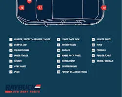
BIW nomenclature refers to the naming convention used for the parts of a Body in White (BIW). The nomenclature is typically used by engineers and technicians to identify the different parts of the BIW and to communicate with each other about the parts.
The BIW nomenclature is typically based on a combination of the part's function, location, and material. For example, the part that supports the front of the car might be called the "front bumper" or the "front impact beam." The part that supports the roof of the car might be called the "roof rail" or the "roof reinforcement."
- Function: The function of the part is the most important part of the nomenclature. For example, a part that supports the front of the car would be called a "front bumper" or a "front impact beam."
- Location: The location of the part is also important. For example, a part that is located on the side of the car would be called a "side panel" or a "side member."
- Material: The material that the part is made of can also be used in the nomenclature. For example, a part that is made of steel would be called a "steel bumper" or a "steel impact beam."
- Front bumper: The front bumper is the part that protects the front of the car from damage in a collision. It is typically made of plastic or metal.
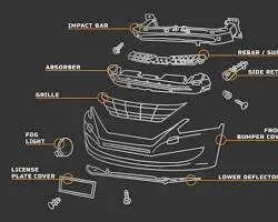
- Front impact beam: The front impact beam is a part of the car's structure that helps to absorb the energy of a collision. It is typically made of steel.
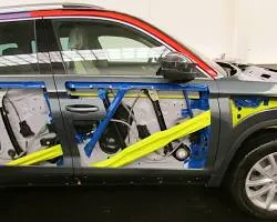
- Side panel: The side panel is the part of the car that forms the side of the body. It is typically made of sheet metal.
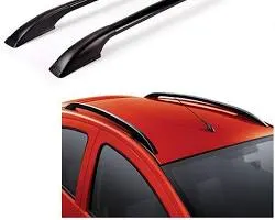
- Roof rail: The roof rail is the part of the car that supports the roof. It is typically made of steel.
-
 3. What is a fixture & its types?
A fixture is a work-holding or support device used in manufacturing to hold and locate a workpiece during machining, assembly, inspection, or other operations. Fixtures are used to ensure that the workpiece is held in the correct position and orientation, which is essential for accuracy and repeatability.
There are many different types of fixtures, each designed for a specific purpose. Some common types of fixtures include:
- Jigs: Jigs are fixtures that guide the cutting tool during machining. They are typically used for complex or precision machining operations.
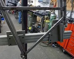
- Fixtures: Fixtures are work-holding devices that are not designed to guide the cutting tool. They are typically used for simpler machining operations or for assembly operations.
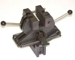
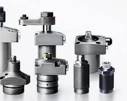
- Clamping devices: Clamping devices are used to hold the workpiece in place in a fixture. They can be mechanical, hydraulic, or pneumatic.
- Locators: Locators are used to locate the workpiece in a fixture. They can be pins, dowels, or vee blocks.
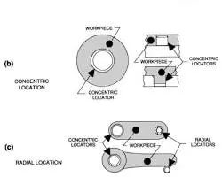
- Indexing fixtures: Indexing fixtures are used to position the workpiece in a specific angular orientation. They are typically used for machining operations that require multiple cuts at different angles.
The type of fixture that is used will depend on the specific application. For example, a jig would be used for a complex machining operation that requires the cutting tool to be guided in a specific path. A fixture would be used for a simpler machining operation or for an assembly operation.
The materials used to make fixtures vary depending on the application. Steel is a common material for fixtures that need to be strong and durable. Aluminum is a common material for fixtures that need to be lightweight. Plastic is a common material for fixtures that need to be non-conductive.
4. What is the basic principle of fixture design?
The 3-2-1 principle is a method of locating a workpiece in a fixture that ensures that the workpiece is held in the correct position and orientation. The principle states that three locating pins should be used to locate the workpiece in the X-Y plane, two locating pins should be used to locate the workpiece in the Z-direction, and one locating pin should be used to prevent the workpiece from rotating.
The 3-2-1 principle is a simple and effective way to ensure that the workpiece is held in the correct position and orientation. It is commonly used in manufacturing, assembly, and inspection.
Some of the benefits of using the 3-2-1 principle:
- Accuracy: The 3-2-1 principle ensures that the workpiece is held in the correct position and orientation, which helps to improve the accuracy of the machining process.
- Repeatability: The 3-2-1 principle also ensures that the workpiece can be repeatedly located in the same position, which is important for mass production.
- Efficiency: The 3-2-1 principle can help to improve the efficiency of the machining process by reducing the time it takes to set up the fixture and preventing the workpiece from moving during machining.
- Cost-effectiveness: The 3-2-1 principle can help to reduce the cost of the fixture by minimizing the number of components required.
- Chassis rails: The chassis rails are the long, horizontal members of the car's structure that provide support for the body. They are typically made of steel.
Examples of the 3-2-1 principle in action:
- Machining a part with a cylindrical surface: The three locating pins would be located in the center of the cylindrical surface. The two locating pins would be located on the side of the part, one above and one below the cylindrical surface. The one locating pin to prevent the part from rotating would be located in the center of the cylindrical surface.
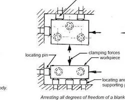
- Assembling a car door: The three locating pins would be located in the center of the door frame. The two locating pins would be located on the side of the door, one above and one below the door frame. The one locating pin to prevent the door from rotating would be located in the center of the door frame.
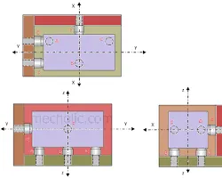
- Inspection of a machined part: The three locating pins would be located in the center of the part's features. The two locating pins would be located on the side of the part, one above and one below the features. The one locating pin to prevent the part from rotating would be located in the center of the part.
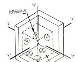
The 3-2-1 principle is a versatile and effective way to ensure that workpieces are held in the correct position and orientation during manufacturing, assembly, and inspection.
5. Elaborate types of BIW Stations.
main types of BIW stations:
- Geo Station: The geo station is where the geometry of the car body is defined. This includes the dimensions and shape of the body panels, as well as the location of the various features, such as the doors, windows, and bumpers.
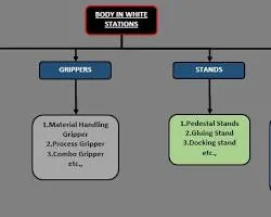
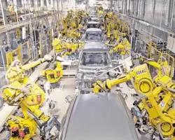
- Respot Station: The respot station is where the car body is welded together. This is a critical process, as the welds must be strong enough to withstand the forces that the car will be subjected to during use.
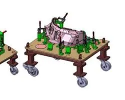
- Pedestal Weld/Rivet Station: The pedestal weld/rivet station is where the car body is welded or riveted together using a pedestal. This is a less automated process than the respot station, but it is often used for smaller parts or for parts that are difficult to access.
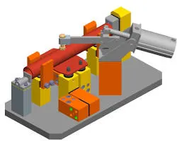
- Loading Station: The loading station is where the car body is loaded onto the assembly line. This is a critical process, as the car body must be properly aligned so that it can be assembled correctly.
- Buffer Station: The buffer station is where the car bodies are stored between stations. This allows the assembly line to operate smoothly, even if there are delays at one station.
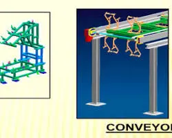
- Marriage Station: The marriage station is where the car body is married to the chassis. This is the final step in the BIW process, and it marks the completion of the car body.
- Curing Station: The curing station is where the car body is cured after it has been painted. This is a critical process, as the paint must be cured properly so that it is durable and long-lasting.
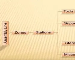
These are just some of the main types of BIW stations. The specific types of stations that are used will vary depending on the car manufacturer and the specific design of the car.
6. What are the basic terminologies used in the BIW fixture?
basic terminologies used in the BIW fixture:
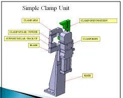
- NC/Mylars/Fingers: NC stands for Numerical Control. Mylars are thin, flexible sheets of plastic that are used to make templates for the fixture. Fingers are the components of the fixture that are used to hold the workpiece in place.
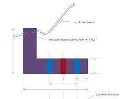
- PLP (Principle Locating Points): PLPs are the points on the workpiece that are used to locate it in the fixture. These points are typically machined on the workpiece and are used to ensure that the workpiece is held in the correct position and orientation.
- Blade: A blade is a component of the fixture that is used to clamp the workpiece in place. Blades are typically made of steel and are designed to grip the workpiece securely.
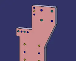
- Riser: A riser is a component of the fixture that is used to support the workpiece. Risers are typically made of steel and are designed to prevent the workpiece from moving during the manufacturing process.
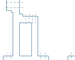
- Shim: A shim is a thin piece of material that is used to adjust the position of the workpiece in the fixture. Shims are typically made of metal or plastic and are designed to fill in any gaps between the workpiece and the fixture.

- CMM: CMM stands for Coordinate Measuring Machine. A CMM is a machine that is used to measure the dimensions of objects. CMMs are used to inspect the workpiece to ensure that it meets the required specifications.
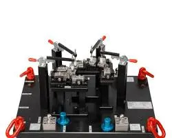
These are just some of the basic terminologies used in the BIW fixture. The specific terminologies that are used will vary depending on the specific type of fixture and the manufacturer.
- Jigs: Jigs are fixtures that guide the cutting tool during machining. They are typically used for complex or precision machining operations.