INTRODUCTION TO BIW FIXTURES - Part 2
Answer:
TYPES OF BIW STATIONS:
Figure 1. BIW Station flow chart
BIW stations are classified into four types.They are,
- TOOLS
- GRIPPERS
- STANDS
- MISCELLANEOUS
A. TOOLS: A Tool is a fixture which consists of Number of units together to hold a car part in general.Types of tools are as follows,
- Geo Tool
- Respot Tool
- Marriage Tool
- Framer Tool etc.,
1.GEO TOOL:
- A Geo tool is a fixture in which the geometry of the panels which are welded together is defined accurately.
- The pin tolerance for a geo pin will be of closer tolerance i.e 0.15 in general.
- For example: consider panel hole size 20mm,then the pin dia should be 19.85mm.
- It is a veryprecise fixture.
- Pin should be in undersize compared to the hole.
Figure 2. Geo Tool
2. RESPOT TOOL:
- It is a fixture in which the remaining weld spots which are not achieved geo tool are welded for the pre welded panel from the geo tool.
- The weld spot which has been done in this tool is only for rigid or stifness prpose.where the geometry of the panels are already controlled in Geo Tool.
- For example: consider panel hole size 20mm,then the pin should be 19.72mm.
- The pin tolerance for a respot pin will be of tolerance with -0.28 in general.
Figure 3. Respot Tool
3. MARRIAGE (OR) HEMMING TOOL:
- A Marriage Tool is a fixture in which the inner pannel assembly & outer pannel assembly are joined.
- Hemming in case of closure paanels.
.
Figure 4. Hemming Tool
4. FRAMER TOOL:
- The station after marriage tool is the framer tool.
- In this tool roof will be attached from the output of the marriage tool.
- After roof is attached with the help of framer tool.A car will now form a frame so the name arise is framer tool.
5. CHECKING TOOL:
- As from name we understand this type of fixtures are used for the checking purpose of the part or assemblies.
- A checking fixture is used to check the automobile parts or assemblies, ensuring all the coordinates,relative dimensions & positions as per the tolerances
- A checking fixture can be a gauge type, fixed typed & automated checking fixture.
- A checking fixture is a tool where workpiece is hold & various measuring gauges are introduced to ensure the dimensions & repeatability.
Figure 5. Checking Fixture
B. GRIPPERS: A gripper is a device or a fixture which holds the car panel, and is fixed to manipulating end of a robot or an end effector also known as EOAT - End Of Arm Tooling.Gripper should be in less weight so it is made up of frame like structures. Types of grippers are as follows,
- Material Handling Gripper.
- Process Gripper.
- Combo Gripper.
- Dual Gripper.
1. MATERIAL HANDLING GRIPPER:
- Material Handling Gripper are designed for handling the car panel from one tool (station) to other tool (station).
Figure 6. Material Handling Gripper
2. PROCESS GRIPPER:
- As name suggests, this gripper are used to carryout soeme process like gluing,welding,riveting etc., in addition with matterial handling.
- In Process gripper, either material handling will be done or some specific process will be done.
- It can not do Multitasking (both process like gluing and material handling at one/same time cant be done in process gripper).
Figure 7. Process Gripper
3. COMBO GRIPPER:
- Combo gripper are designed for handling the car panel from one tool (station) to other tool (station). Also with the combination of weld gun at another side of the gripper for welding.
- Combo gripper can do multi tasking (both process like gluing and material handling held at same time in Combo gripper).
- COMBO GRIPPER = GRIPPER + WELD GUN
Figure 8. Combo gripper
4. DUAL GRIPPER:
- Dual gripper are designed for handling the car panel from one tool (station) to other tool (station) with two sided gripper.
- As shown in the figure below the gripper will be on both side.
- DUAL GRIPPER = GRIPPER + GRIPPER
Figure 9. Dual Gripper
C. STANDS: Stands are use to hold the components like Glue gun,sealer gun,weld gun etc., where these stands are fixed to the floor/ground permanently. The types of stands are as follows,
- Pedestal stands.
- Gluing stands/Sealer stand.
- Docking stands.
- Dtae stamp stand.
1. PEDESTAL STANDS:
- Weld gun is mounted to a fixed stand which is grounted to the floor permanently,where the process gripper carries the car panel to weld the spot with this fixed weld gun.
Figure 10. Pedestal gun stand
Figure 11. Pedestal gun stand
2. GLUING & SEALER STAND:
- Gluing gun or sealer gun is fixed to a welded or standard stand which is grounted to the floor permanently.
Figure 12. Gluing & Sealer stand
3. DOCKING STAND:
- When robots are selected for multitasking purpose like material handling & welding, which cannot carry both due to some limitations (pay load capacity of the robot or space constraint) the robot will drop & pick the gripper or gun after completing the respective operation with the help of docking stand.
Figure 13. Docking stand
4. DATE STAMP STAND:
- The panel will get the date embossed on to it, with the date stamping device which is mounted on this date stamp stand.
Figure 14. Date stamp stand
D. MISCELLANEOUS: The types are as follows,
- Curing.
- Buffer stand/storage.
- Racks.
- Takeout trolleys.
- conveyors.
1. CURING:
- After gluing it needs some time to cool down or to get dry.
- So we hold/hang the assemblies on curing,then it will move the panel to other stations.
- During the moving time the glued sides will be get cooled.
2. BUFFER STAND/STORAGE:
- Buffer storage are very similar.It is used mainly for storage purpose.
- It has provide sections,where n-numbers of assemblies kept after the operations completed (aproxymately between 10 - 15) as per designed.
- And these assemblies can be moved together for inventory purpose.
- While the machine is under maintanance, the panels has to be kept in stock for future supplies as per the production details.So here the Buffer stand palys a vital role,where the panels are kept in the provided sections and moved to stores for inventory pupose in a easy way.
Figure 15. Buffer stand
3. RACKS:
- Racks are nothing but where the panels or sub-assemblies kept in their allocation area.
- The Rack must contain several details like part name, part no.,model name etc., for identification purpose. so that the parts can be taken from the rack easily.
- The rack as to be designed in such a way that the identification of parts would be made esay.
- The parts should be kept above or below where the details are engraved in the racks.So that by identifying the details the parts can be handled by the operator easily without any confussion which consume time and may affect the production capacity.
4. CONVEYORS:
- Conveyors are the rotating path which transports the parts to the next station which kept over it.
- Conveyors can be of belt or chain type.
- It will actualy consist of a pallet or fixture type structure,where the panel will be kept and moved to the other station.
- This process will be in keep on rotation or moving from one end to other end as shown in the figure below.
Figure 16. Conveyors
5. TAKE OUT TROLLEY:
- Take ou trolley is used to take the car panel out of the robotic working cell between the cycle for inspection purpose.
- It is used to take out some panels for inspection pupose to rectify the process is going right or not between the cycle.
Figure 17. Take out trolley
Figure 18. Take out trolley
Hence,the types of BIW stations are elobrated above.
Question NO.6 - What are the basic terminologies used in the BIW fixtures ?
Answer:
BASIC TERMINOLOGIES USED IN BIW FIXTURES:
The basic terminologies used in BIW fixtures are,
- NC/Mylars/Fingers.
- PLP (Principle locating points).
- Blade.
- Raiser.
- Shims
- Rough Locators.
- Hardwares.
- CMM.
- UNITS.
- Number plates.
- Co - ordinate plates.
- Name plate.
- Clamp arm.
- Pivot.
- Class 'A' surface (or) Skin surface.
- Reed switches.
- Sensors.
A. NC/MYLARS/FINGERS:
- Mylars are the part which are holding the panel from top & bottom.
- It is a Jaw type, during welding it wont deforms from its position.
- It is also known as fingers.
- It dont allow the deformation of the part due to welding stresses.
- Mylars are of two types,they are
- Clamping mylars.
- Resting mylars.
CLAMPING MYLARS: The part which are holding the panel from top is known as Clamping mylars.
Figure 1. Clamping Mylars
RESTING MYLARS: The panel which rests on the part is known as Resting Mylars.
Figure 2. Resting Mylars
Figure 3. MYLARS
Every clamping mylar will have a resting mylar.
B. PLP (Principle Locating Point):
- These are the points which are used for the accurate location of the panels sub-assemblies to maintain the geometry of the assembly.
- There are lots of holes on the panel which are not accurate due to stamping operations. so the PLP are defined in the drawings.
- The PLP holes must be very much precise.
Figure 4. PLP(Principle Locating Point)
C. BLADE:
- Blade are the plates which are attached to raiser.
- Blade is also attached or mounted with cylinders,arms etc.,
Figure 5. BLADE
D. RAISER:
- Raiser is a manufacturing part used to raise/height the assemblies of fixtures.
- One end of the raiser will be attached to the base unit while the other end will be attached to the Blade.
- Raiser can be of two types.They are,
- 'L' type raisers.
- Square tube raisers.
- 'L' TYPE RAISERS: 'L' type raisers are of welded type.Where the stiffner will be added at the centre for support.As shown in the below figure the wedge shaped structure is known as stiffner which is used as a support / to withstand load.
Figure 6. 'L' TYPE Raiser
- Square Tube Raisers: Square tube raisers are of frame type.
Figure 7. Square Type Raiser (Frame type)
E. SHIMS:
- In general, A shim is a thin and often tapered or wedged piece of material, used to fill small gaps or spaces between objects.
- Shims are typically used in order to support, adjust for better fit, or provide a level surface.
- Shims may also be used as spacers to fill gaps between parts subject to wear.
- Shims are the small parts which comes with the thickness of 0.1mm,0.2mm,0.5mm,1.0mm etc.
- These will compensate the stack up tolerance which reflects at the mylars.
- We give tolerance to all parts of the fixture.Due to this tolerance the mylars will either lift up moves down from its defined position.
- To adujust the mylars for getting the defined position we use shims.
- Shims will be added above the mylar for adjusting according to tolerance.
Figure 8. Shims
- Application of shims:
-
In automobiles, shims are commonly used to adjust the clearance or space between two parts. For example, shims are inserted into or under bucket tappets to control valve clearances. Clearance is adjusted by changing the thickness of the shim.
-
In assembly and weld fixtures precision metal shims are used between two parts so that the final production parts are created within the product drawing's specified tolerance.
- Types of shim: Types of shims are,
- wood shim.
- stone shim.
- plastic shim.
- metal shim.
- Paper shim.
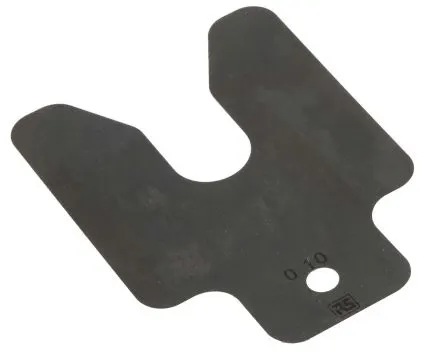
Figure 9. Shim
F. ROUGH LOCATORS:
- Rough locators are used in manual fixtures usually provided at the end of panels.
- It acts as a guide for the operator and helps to place the panel in the fixture in right poition.
- Also used to identification purpose,to understand for operator easily.
Figure 10. Rough Locator
Figure 11. Rough Locator
G. HARDWARES:
- Hardwares are nothing but the fasteners which are used to connect/lock the parts of the fixture together in fixed postion.
- The hardwares are Hexagonal bolt,Hexagonal Nut,Allen bolt,Washers,self locking nuts,etc.
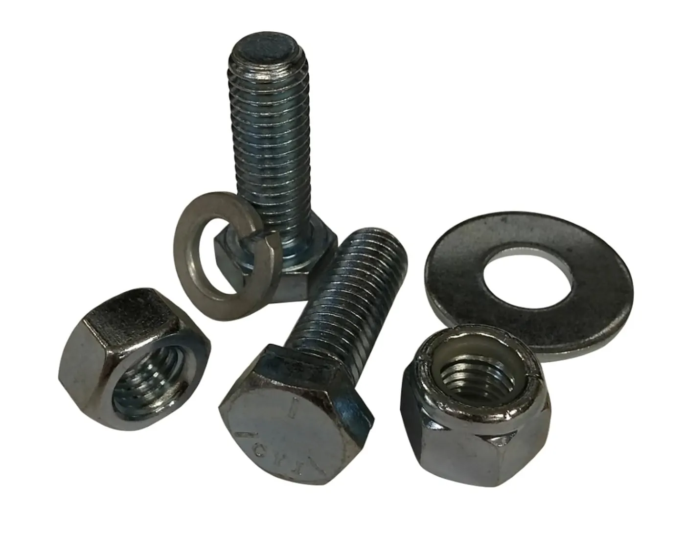
Figure 12. Hexagonal Bolt,Nut,Washers (Fasteners)
Figure 13. Allen Bolt with Hexagonal Nut
H. CMM:
- CMM - Coordinate Measuring Machine.
- A coordinate measuring machine (CMM) is a device that measures the geometry of physical objects by sensing discrete points on the surface of the object with a probe.
- Various types of probes are used in CMMs, including mechanical, optical, laser, and white light.
- Depending on the machine, the probe position may be manually controlled by an operator or it may be computer controlled.
- CMMs typically specify a probe's position in terms of its displacement from a reference position in a three-dimensional Cartesian coordinate system (i.e., with XYZ axes).
- CMM Plays a vital role in large number of industries like automobile,aerospace,Healthcare,Food processing,Paper,Plastics,semiconductors,etc.
Figure 14. CMM (Coordinate Measuring Machine)
- TYPES OF CMM: There are four basic types of CMM.They are,
- Bridge type CMM. -- a. Moving Bridge b.Fixed bridge
- Cantilever type CMM.
- Gantry type CMM.
- Horizontal arm CMM.
- Column type CMM.
1. BRIDGE TYPE CMM:
a.Moving Bridge type CMM:
- Most widely used.
- Has stationary table to support work piece to be measured and a moving bridge.
- Advantages: Reduce bending effect.
- Disadvantages: With this design the phenomenon of Yawing can occur which affects the accuracy.
b.Fixed Bridge Type:
- In Fixed bridge type, the bridge is rigidly attached to the machine bed.
- This design eliminates the phenomenon of yawing and provides high rigidity.
2. CANTILEVER TYPE CMM:
- Avertical probe moves in a Z-Axis.
- Carried by a cantilever arm that moves in the Y-Axis.
- This arm moves lateraly through the X-axis.
- The cantilever design offers a long table with relatively small measuring ranges in the other two axis.
- Suitable for measuring long,thin part.
- Advantages: A fixed table allows good accessibility to the work piece.
- Disadvantages: The bending is caused by a cantilever design.
3. GANTRY TYPE CMM:
- The support of work piece is independent of the X & Y axis,both are overhead,supported by four vertical columns rising from the floor.
- This setup allows you to walk along the work piece with the probe,which is helpful for extremely large piece.
4. HORIZONTAL ARM TYPE CMM:
- As a moving arm,and the probe is carried along the Y-axis.
- Advantages: Provides a large area,unobstructed work area.
5. COLUMN TYPE CMM:
- Often refered to as Universal Measuring Machine instead of CMM.
- The column type CMM construction provides exceptional accuracy and rigidity.
- These machines usually reserved for gage rooms rather than inspections.
Figure 15. Mechanical structure of CMM
I. UNITS:
- The fixture is the assemblies of different types of units.
- There are different units like,
- Base unit.
- Pin unit.
- Clamping unit.
- Rest unit. etc.
1.Base unit: Base unit is the unit designed to mount all other units such as Clamp unit, pin unit,rest unit etc., of tool, also other parts necessary for a tool like pneumatic valve box,trunking cable path will also be mounted on to be a base unit.
Figure 16. Base unit
2. Pin unit: Typically, the locating pins are used to locate a body part in a position sufficiently accurate to execute a welding process.The body part is constrained by a set of appropriately locating pin so totalconstraint by locating pin should be fully constrained at all times to prevent anymovement.
Figure 17. Pin Unit
Figure 18. Pin unit attached with sensor
3. Clamping Unit: Clamping unit is used to clamp the part which is to be welded after location using pin unit. Clamping is achieved with the help of pneumatic cylinders and clamp arms.
Figure 19. Clamping Unit
J. NUMBER PLATES:
- Number plate is an aluminium embossed plate on each unit.
- Each unit has a number which is embossed on that aluminium plate for identification purpose.
- To recognize the unit easily number plates are used.
Figure 20. Number plates without any embossing
K. CO-ORDINATE PLATE:
- In every fixture we have tooling holes,where every unit will be fixed through it.
- These holes will reflect the postion of the units and also the panels.
- So these holes in coordinate plates will be useful for checking in CMM.
L. NAME PLATE:
- In name plate where the basic informations like panel name, model name, panel number,fixture type,fixture weight,Company name,Asset ID etc. will be engraved or embossed and attached with the fixture.
Figure 21. Tool Name plate of Diamler India Commercial Vehicles Pvt. Ltd.
Figure 22. Name plate
M. CLAMP ARM:
- Clamp arm is a part of clamping unit which moves over the axis.
- Clamp arm is which the clamp & mylars mounted.
- Clamp arm is a rotatable one which helps to hold the panel firmly.
Figure 23. Clamp Arm
Figure 24. Clamp arm
N. PIVOT:
- Pivot is a axis about which the clamp arm rotates.
- Thus the rotation tends the clamp to rotate & hold the panel.
Figure 25. Pivot
O. CLASS 'A' SURFACE (or) SKIN SURFACE:
-
In automotive design, a class A surface is any of a set of freeform surface of high efficiency and quality. Although, strictly, it is nothing more than saying the surfaces have curvature and tangency alignment – to ideal aesthetical reflection quality, many people interpret class A surfaces to have G2 (or even G3) curvature continuity to one another.
-
Class A surfacing is done using Computer aided industrial design applications. Class A surface modellers are also called "digital sculptors" in the industry. Industrial designers develop their design styling through the A-Surface, the physical surface the end user can feel, touch, see etc.
-
In automotive design application Class A surfaces are created on all visible exterior surfaces (ex; body panels, bumper, grill, lights etc.) and all visible surfaces of see-touch & feel parts in interior (ex: Dashboard, seats, door pads etc.). This can also include beauty covers in the engine compartment, mud flaps, trunk panels and carpeting.
- In the product design realm, Class A surfacing can be applied to such things like housing for industrial appliances that are injection moulded, home appliances, highly aesthetic plastic packaging defined by highly organic surfaces, toys or furniture.
- Aerospace has styling and product design considerations in interiors like bezels for air vents and lights, interior roof storage racks, seats and cockpit area etc. In recent years Airbus used ICEM Surf for generating the exterior surface geometry for Aesthetic and aerodynamic optimisation before delivering the surface to downstream CAD software like CATIA.
- While designing a fixture to a skin surface the clamping material should be soft,so that it could not able to left any impression or dent over the skin.In general nylon wiil be used for clamping purpose.
Figure 26. Class A - suface
Figure 27. Class 'A' - Surface development of Rear bumper assembly
P. REED SWITCHES:
- These are electric parts used in automated fixtures which run through PLC programming.
- These electrical switches are operated by an applied magnetic field.
- Reed switches are placed in the sides of the pnematic cylinders to confirm the clamping of panels.
Figure 28. Reed Switches
Q. SENSORS:
- Sensors are also an electical part like reed switch,it is also used in automated fixtures.
- Sensors will be attached where the main part of panel & sub-assemblies of pannels are placed.
- If in case operator forgot/missed to keep one sub-assemby in fixture,then after welding process it cant be assembled to the car due to the missing part and it may leads to a big problem also affect the production capacity,time and cost.So to avoid such problems sensors are introduced under each and every assembling parts.
- Sensors are also introduced for the awarness of operators.So that they can place every sub-assemblies without fail which will help to run the assembly line smoothly without affecting such factors like production capacity,cost,time,etc.,
Figure 29. Sensor attached in Pin Unit
Figure 30. Sensor attached in claming unit
Hence, the basic terminologies used in the fixtures are explained in detail.