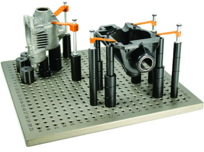
Week 1:- Introduction to BiW and Fixtures Challenge
1 BIW:
- BIW - Body In White.
- BIW refers to the welded sheet metal components which form the vehicles structure to which the other components (like engine, chasis, exterior & interior trims) will be married or assembled.
- The stage in automotive design or automobile manufacturing in which the car body sheet metal components are been assembled by welding & by other joining process.
- The structural performance of an automobile can be determined by the performance of the body, referred to as BIW.
- BIW is the steel structural shell composed of generally steel panels welded together. BIW structure supports theoverall other subsystems in the vehicle.
- To achieve an efficient car design it is necessary to have the BIW design with optimized mass.
- BIW connected all the components in the vehicle like Powertrain, driveline.
- BIW encloses, protects the passengers & cargos. The BIW design needs to be stiff to support the mass & securely keep them all integrated. Further it needs to resist & absorb energy during the event of vehicle crash.
- BIW design also needs to be light weight structure so that there can be a posibility of reduced fuel consumption & increased performance.
- The structure is made from Steel or Aluminium panels (0.7 - 2.0 mm thickness). The pannels are stamped into shape and then spot is welded together.
- BiW constitutes about 27% of a car’s weight.
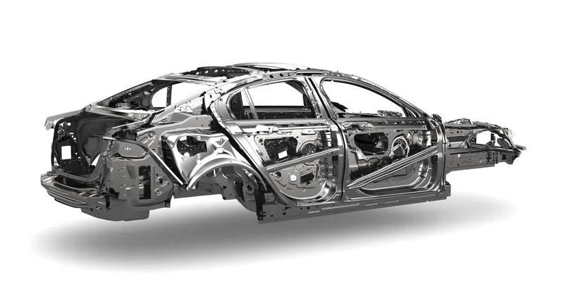
In general the BIW consists of nearly 300 - 350 components.
In the new advanced BIW architecture, the entire body was designed with 58 major parts.
MAJOR INFLUENCING FACTORS OF BIW DESIGN:
- Number of parts.
- Materials.
- Internal structural reinforcements.
The Principles that should always be Considered in BIW designs are:
- Effective load paths in the BIW architecture with minimum number of components in the design.
- Material distribution in the BIW considering the bending & torsion stiffness of the BIW.
- Internal Reinforcement location which could be lead to efficient performance increase.
- Material optimization method on a full vehicle crash analysis.
There are two types of Body structures in use, They are:
- Monocoque Body structure.
- Frame Mounted Body structure.
1.MONOCOQUE BODY STRUCTURE:
In this type of Body structures, Chasis is in built in the BIW itself and there is no seperate chasis. Wheels are directly mounted to the BIW with the help of suspension system.
2.FRAME MOUNTED BODY STRUCTURE:
In this type of body structures, Body is mounted on seperate chasis or frame & wheels are mounted on the chasis not to the body.
BIW PARTS:
BIW structures can be divided into following sub-structures:
- Underbody structure.
- Front End Structure.
- Body side structure.
- Closures.
- Roof.
All those sub structures consist of following major panels:
- UNDERBODY STRUCTURE:
- Dash panel - Provides partition between Engine & the driver cabin.
- FRT Floor - Provides base for the seats.
- Raiser - Connects front floor to Rear floorby providing level difference.
- Rear Floor - Floor on the rear of the car & provides partition from ground and base for the rear seats.
- Rear wheel house.
- FRONT END STRUCTURE:
- Plenum Panel - A chamber located between throttle body & runners of the intake manifold.
- FRT Wheel House (Fender) - Is an encasement around the Front wheel.
- Wing Panel - Outer most side panel in the front.
- Cowl - Portion of the body bounded by the front fenders, the base of the wind shield and the rear edge of the hood.
- Upper Tie Bar - Upper panel in front connecting the two sides of front structures.
- Lower Tie Bar - Lower panel in front connecting the two sides of front structures.
- BODY SIDE STRUCTURE:
- A Pillar - Front most support to the roof.A- pillar are the most stylistically interesting for a car fans Other notable aspects of the A-pillar
- B Pillar - Second support to the roof. B - pillar plays a key role providing strength to a mid section to a vehicle.
- C Pillar - C is rear most support to the roof in caseof two row seating system, it will be third one. C-Pillar is often the most heavily leveraged pillar from a styling perspective. BMW has made the C - PILLAR their own distinctive curved C - pillar called the Hoffmeister kick that appears in some format in all of their cars. Coupes also rely heavily on the C-pillar to create streamlines shape.one of the most iconic is from Ford Mustang.
- D Pillar - D is the fourth support usually rear side of quarter panel. D pillar is really the end of the line in many ways this pillar is designed for the necessity to house the rear door in a wagon or SUV.
- Ring Panel - A structure panel connecting the rear & front portion.
- Quarter Panel - Rear most panel of a body side structure.
- Drip rails / Gutters - An exposed channel applied to the roof over the side windows to direct water away from the windows.
From the above picture the Placements of A,B,C,D pillars can be easily understand.
B - Pillar design and details are shown in the above picture.
From the above picture the Roof panel & Rear quarter panel can be seen
- CLOSURES:
- All Doors
- Hoods / Bonnets - A hinged panel providing access to the engine compartment.
- Roofs.
- Headers - Structural member above the wind shield at juncture with the forward edge of the roof panel.
- Bows.
REINFORCEMENT COMPONENTS:
The part which are used to support and provides stiffness and strength to other components of BIW is known as Reinforcement component. Some of the reinforcement components are shown below in the picture.
2 DEFENITION OF NOMENCLATURE:
- The devising or choosing of names for things, especially in a science or other discipline.
- In formal, the term or terms applied to someone or something.
BIW NOMENCLATURE:
- Hence from the definition of nomenclature we came to know that the terms/names applied to the BIW COMPONENTS is known as BIW NOMENCLATURE.
- The terms are standard but they differ in some countries.
- As automotive industries spread world wide, the terms and standards will be different for similar components.
- For example, One component of BIW is known as inner wing pannel in UK description otherside the same component of BIW is known as Motor compartment side panel in US description.
- Below I have been attached some common terms of BIW which differs from UK to US descriptions.
BIW NOMENCLATURE
3 FIXTURE:
- A fixture is a device which holds the work piece to be processed (welded) by using 3-2-1 Principle.
- In general a welding fixture tool consists of Number of units together to hold the car pannel and is mounted on a base unit.
- Fixture has to be quite stable and rigid to withstand the welding stresses.
- Welding fixtures are used to hold the parts in the required shape and is used from smaller parts to larger parts of a plane. Before welding the parts are placed and positioned for the required shape. After clamping the parts by means of clamping unit welding work will be carried out.
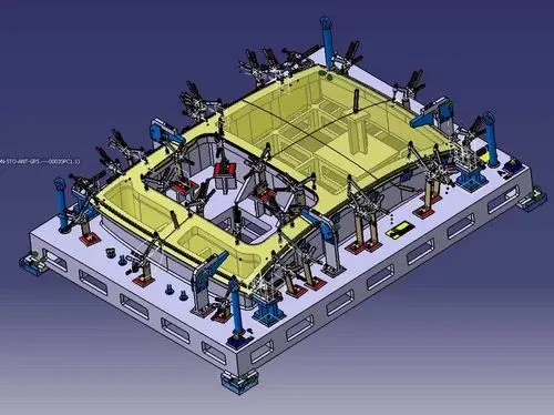
Fixture
FIXTURE DESIGN CRITERIA:
The criteria for designing the fixture are,
- Design specifications.
- Factory standard.
- Ease of use & safety.
- Economy.
BIW FIXTURE REQUIREMENTS:
- It should prevent dissortion in work piece during welding operation.
- The clamping need to be light but firm means the clamping force should be able to maintain the part at its required position without damaging the part.
- Placement of clamping need to be clear of welding area.
- Fixture need to be quite stable & rigid to withstand the welding stresses.
- The fixture should maintain its consistancy to do defect free operation.
TYPES OF FIXTURE:
- Pre-production fixture.
- Production fixture.
- Checking fixture.
PRE - PRODUCTION OPERATION (PPO) FIXTURE:
- These fixtures are designed as the prototype fixture to check & study the feasibility of initial batch production.
- This type of fixtures are used to take the trial and errors from the components.While in trial and error, the errors are absorbed and corrections are made till the part/components attains its requirement as per the drawings.
- we have to maintain the cost ofthe car as low as possible.since, Pre- production fixtures tooks more cycle time & lots of time & cost we directly move towards the Production fixture by considering standards & checklist to ensure the free production.
PRODUCTION FIXTURE:
- This type of fixture are used for Mass production purpose.
- The production fixtures must be easy for maintainance purpose.
- It should be easy to assemble and dis-assemble the parts from the fixtures to minimize the time consumption.
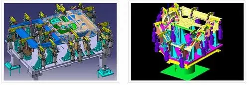
Production Fixture
CHECKING FIXTURE:
- As from name we understand this type of fixtures are used for the checking purpose of the part or assemblies.
- A checking fixture is used to check the automobile parts or assemblies, ensuring all the coordinates,relative dimensions & positions as per the tolerances
- A checking fixture can be a gauge type, fixed typed & automated checking fixture.
- A checking fixture is a tool where workpiece is hold & various measuring gauges are introduced to ensure the dimensions & repeatability.
Checking Fixture
4 PRINCIPLE OF FIXTURE DESIGN:
- For a fixture designer, the major portion of design time is spent on deciding how to locate the work piece in the fixture.
- For any free body there are total 12 degrees of freedom as below,
- 6 translation degree of freedom
- X+
- X-
- Y+
- Y_
- Z+
- Z-
- And 6 rotational degree of freedom
- Clockwise around X axis (CROT -X)
- Anticlockwise around X axis (ACROT - X)
- Clockwise around Y axis (CROT -Y)
- Anticlockwise around Y axis (ACROT - Y)
- Clockwise around Z axis (CROT -Z)
- Anticlockwise around Zaxis (ACROT - Z)
- we must fix all 12 degrees of freedomin order to locate the work piece in the fixture.
- so, 12 degrees of freedom of the work piece need to be fixed & thus we can achieve zero degree of freedom for the work piece.
- Resting - Stability
- Locating - W.r.t datum
- Orienting - W.r.t secondary datum
- Clamping - Ensuring above not disturbed.

A rigid body on a space
PRIMARY LOCATOR:
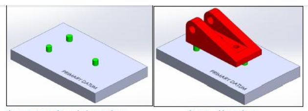
- Axial Movement downward along Z- axis ( No.6 in Fig 1 )
- Rotation about the X & Y axis ( No. 7, 8, 9 & 10 in Fig 1)
 |
| Primary Locators |
- Axial movement along the Y+ axis ( No.3 in Fig 1 )
- Rotation about the Z axis ( No. 11 & 12 in Fig 1 )
 |
| Secondary Locators |
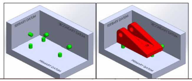
TERTIARY LOCATOR:
- Axial movement along the X axis ( No.2 in Fig 1)
 |
| Tertiary Locator |
Geo station:
In this station geometry of two parts are fixed. it can be either using welding or riveting . In this station precision and geomatry of the finished product is defined Locating pins have closer tolerence of 0/-0.15.
Suppose the hole dia of panel is 16mm then the pin dia minimum can be 15.85.
Diameter of locating pins should be lesser than the panel hole dia. So Tolrence in locating pin is given in negative value.
Respot Station :
Once product comes out of the Geo Station and there are left out spots where spot welding or riveting is to be done. then it is moved to another station , that station is called Re-spot station.
These left out spots may be the due to clamp plan, cycle time,robot reach ability or any other various reasons.
In this station pins ahve tolrence upto 0/-0.28.
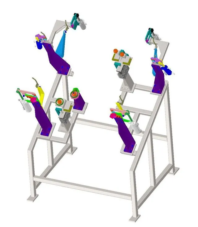
Pedestal Station :
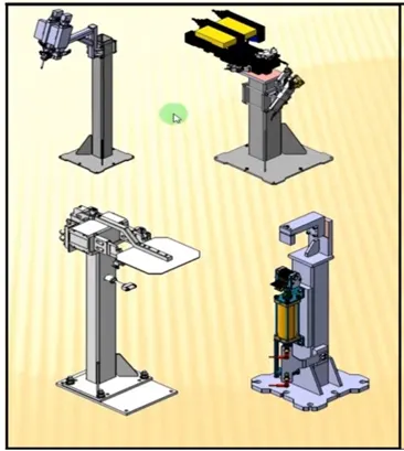
In this station , Pedestal gun is mounted on a tool and panel is manipulated manually or by robot to weld the panels.
Pedestal station is generally a Re spot station.
Re spot station and Pedestal station, both perform same kind of operation . but to decide whether to go for pedestal or a re-spot station some parameters needs to consider like cycle time, floor space, no. of welds, clamp plan, or size of the panel.
Loading Station :
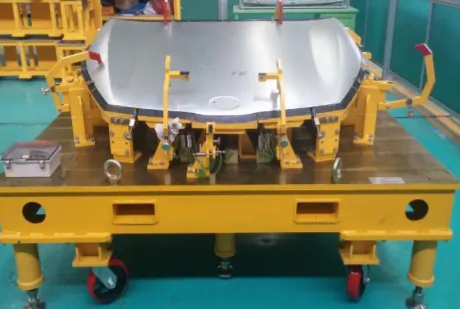
This station is used for loading of panel and same station is used to change the orientation of the if it is required in the upcomin station.
Sometime this station is used when Robots are unable to transfer panel from one station to another.
Buffer Station :
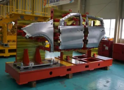
This station is used to make the balance between the process.
Some stations carry out procees in lesser time as compared to their respective stations.In that case panels can be stored in one sation so that assembly line process remains smooth.
Sealer Station :
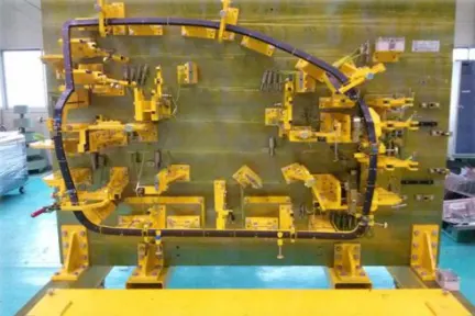
In this station Sealant application is carried out.This process can be carried out manually or by using robots. Sealer is used in between two panels so that panels do not flatter due to friction.
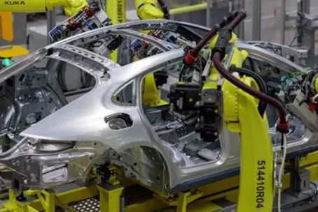
Marriage Station :
In this Station inner and outer panels are joined. In this station to avoid the imprssion on the outer panel(A class surface), copper strips are used in betweenn the weld tip and A-class surface.
Curing Station :
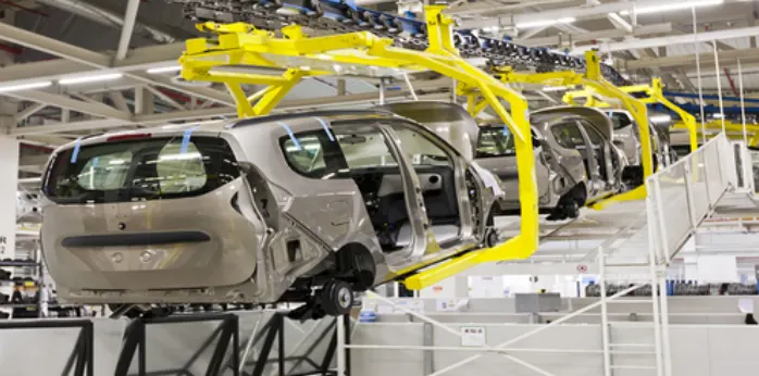
In this Station product recieved after sealing application, is kept idle at ambient temperature, which allows sealent to get dry with better bonding between the panel.
6 Some basic terminologies in BIW
Mylar
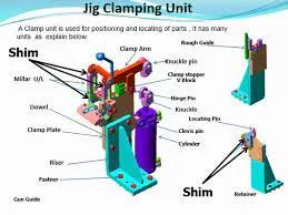
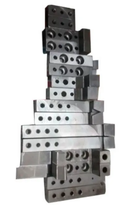
MYLAR is one kind of block that touches the panel and holds or clamps the panel. Mylars are always designed in CAR LINE. Mylar is also called NC(Numerically Controlled)Block. Mylars are mounted on any block or plate with Shimming, So that height of mylar can be adjusted accordingly at the assembly level. For ‘A’ class surfaces Nylon mylars are used. So that surface can be saved from scratches.
Pins
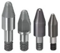
Pins are used to locking the rotational movement of the panel. Generally there two types of Pins, one is Round Pin and another one is a Diamond pin. mostly they use two and three-directional shimming for pins as per the angle of the pin in the carline. In some cases, a collared pin, when the pin is supposed to support the panel as well. For this kind of pin, they provide 3 way shimming irrespective of pin angle to the carline.
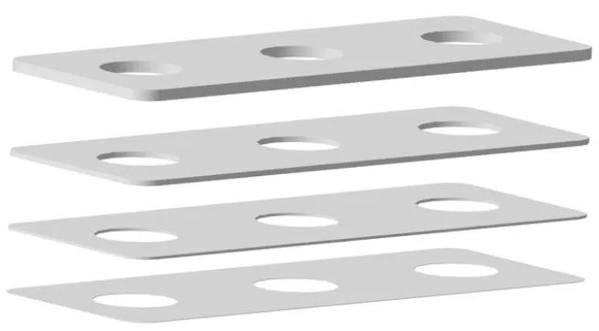
Blades
The plate which connects Riser to the Clamp cylinder is named Blade. This plate plays an important role in building the unit. The plate can be of any shape.
L blocks
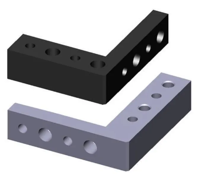
A plate shaped as L is called an L block. This part is used as a connection between mylar and Blade. Generally, L blocks are used to provide shimming. It is not necessary that L blocks are only used for shimming, its uses changes as per the requirements, At some places, it is used just to connect one part to another.
Riser
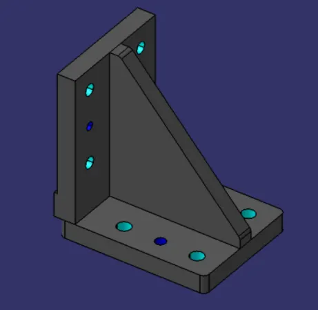
The part which is mounted on the base plate and holds a clamp or pin cylinder on it, is called Riser. Riser can be Standard Part or manufactured part, it varies from project to project. A riser can be a Single part or welded part. Standard risers also have various shapes and sizes.
Welment
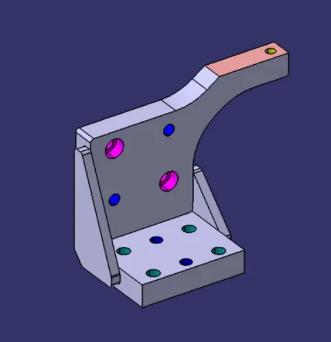
Weldment is the assembly of two or more parts that are joined by welding. To make a weldment it is the thumb rule to have a 5 mm overlay on each other plates so that space can be provided for welding. A weldment can be of any size and any number of plates.
Sensors
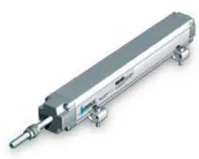
These are mostly used in checking stations. to check hole dimensions.
CMM
A Coordinate Measuring Machine (CMM) is a measuring device to inspect the physical geometry of an object by sensing discrete points on the surface of the object or a part using a sensing probe. When the probe touches a surface, the transducer records the input and sends it as an electric impulse to the computer.