Week 1:- Introduction to BiW and Fixtures Challenge
1.What is BIW & define its parts?
BIW stands for Body in White. BIW is an assemblage of all welded sheet metal panels as before going for priming and painting. BIW refer to the welded sheet metal structure to which other component will be married i.e. engine, chassis, exterior and interior trim.
Body in white or BIW refers to the stage in automotive design or automobile manufacturing in which car body sheet metal ( including door, hoods and deck lids) has been assembled or designed but before the components ( chassis, motor) and trim ( windshields, seats, upholstery, electronics, etc.) have been added. All activities in the production of a vehicle body or shell before it goes to the paint shop are done in a weld shop and the end product of a Weld shop is referred to as BIW.
BIW structure can be divided in following substructures:
- Underbody structure
- Front end structure
- Body side structure
- Closure
- Roof
1) An Underbody Structure consists of following major panels:
- Dash panel - Dash panel provides a partition between engine and the driver/passenger cabin inside car
- FRT Floor - provides a base for seats mounting and provides partition between transmission /propeller shaft/ground and the cabin.
- Riser- Riser connects Front floor to Rear Floor by providing a level difference
- Rear Floor- Rear Floor is the floor on the Rear of the car and provides a partition from ground also provide base for Rear seat mounting.
2) Front end structure consists of following major panels:
- PLENUM Panel - Plenum is a chamber located between the throttle body and the runners of the intake manifold, used to distribute the intake charge evenly and enhance engine breathing.
- FRT wheel house/ Fender - FRT Wheel house or Fender is an encasement around the FRT wheel.
- Wing panel - Wing panel are the outer most side panel in the front.
- Cowl - Cowl is the portion of the body bounded by the front fenders, the base of the windshield, and the rear edge of the hood
- Upper tie bar- Upper tie bar is the upper panel in front connecting the two sides (RH/LH) of Front structure.
- Lower tie bar- Lower tie bar is the lower panel in front connecting the two sides (RH/LH) of Front structure.
3) BODY SIDE structure consists of following major panels:
- A-pillar- A-Pillar is the front most support to Roof.
- B-pillar- B-Pillar is the second support to the roof and situated on the locking side of the Front door.
- C/D pillars- C-Pillar is the Rear most support to roof in case of a two row seats car, or third support to the roof. D-pillar is the fourth support to the roof and usually on the rear side of quarter panel.
- Ring panel - Ring panel is a structure panel connecting the rear portion of the body to front, and constitutes a big part in side structure.
- Quarter panels- Quarter panel is rear most panel of a body side structure.
- Drip rails/Gutters- Drip rails/Gutters is an exposed channel applied to the roof over the side windows to direct water away from the windows and to cover structural welding.
4) Closures consists of following major panels:
- All Doors
- Hood/Bonnet -Hood is a hinged panel providing access to the engine compartment.
5) Roof structure consists of following major panels:
- Roof
- Headers- Header is the structural member above the windshield at the juncture with the forward edge of the roof panel.
- Bows- Those are used to support the roof.
2.What do you understand by BIW nomenclature?
DEFENITION OF NOMENCLATURE:
- The devising or choosing of names for things, especially in a science or other discipline.
- In formal, the term or terms applied to someone or something.
BIW NOMENCLATURE:
- Hence from the definition of nomenclature we came to know that the terms/names applied to the BIW COMPONENTS is known as BIW NOMENCLATURE.
- The terms are standard but they differ in some countries.
- As automotive industries spread world wide, the terms and standards will be different for similar components.
- For example, One component of BIW is known as inner wing pannel in UK description otherside the same component of BIW is known as Motor compartment side panel in US description.
- Below I have been attached some common terms of BIW which differs from UK to US descriptions.
3.What is fixture & its types?
A device which is used to hold, locate and support the component in the manufacturing industry is called fixture. Fixtures ensure to provide the stability to the part when any process is being done on that part. That process can be welding, riveting, grinding, drilling etc. In BIW fixture design Fixture works on 3-2-1 principle.
TYPES OF FIXTURE:
- Pre-production fixture.
- Production fixture.
- Checking fixture.
PRE - PRODUCTION OPERATION (PPO) FIXTURE:
- These fixtures are designed as the prototype fixture to check & study the feasibility of initial batch production.
- This type of fixtures are used to take the trial and errors from the components.While in trial and error, the errors are absorbed and corrections are made till the part/components attains its requirement as per the drawings.
- we have to maintain the cost ofthe car as low as possible.since, Pre- production fixtures tooks more cycle time & lots of time & cost we directly move towards the Production fixture by considering standards & checklist to ensure the free production.
PRODUCTION FIXTURE:
- This type of fixture are used for Mass production purpose.
- The production fixtures must be easy for maintainance purpose.
- It should be easy to assemble and dis-assemble the parts from the fixtures to minimize the time consumption.
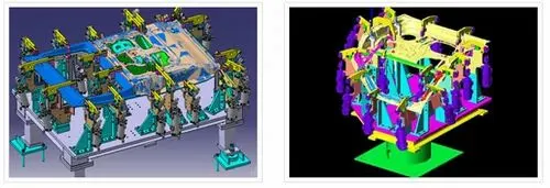
Figure 10. Production Fixture
CHECKING FIXTURE:
- As from name we understand this type of fixtures are used for the checking purpose of the part or assemblies.
- A checking fixture is used to check the automobile parts or assemblies, ensuring all the coordinates,relative dimensions & positions as per the tolerances
- A checking fixture can be a gauge type, fixed typed & automated checking fixture.
- A checking fixture is a tool where workpiece is hold & various measuring gauges are introduced to ensure the dimensions & repeatability.
4.What is the basic principle of fixture design?
Fixture works on 3-2-1 principle.A fundamental concern in metalworking is locating the part to be machined, punched, bent, or stamped relative to the work platform (fixture). For example, a CNC machine tool starts its process at a specific point relative to the fixture and proceeds from there. Hence, the accuracy with which a part is machined is quite dependent on the accuracy with which it is positioned in the fixture.
Accurate locating of not just one part, but each and every part that is loaded into the fixture is crucial. Any variation in part location on the fixture adds to the dimensional tolerance that must be assigned to the finished parts.
Additionally, the method of supporting and securing the part in the fixture affects not only dimensional tolerances, but surface finishes as well. This is true because improper supporting or clamping can temporarily or permanently deform the part. Hence, techniques for supporting and clamping must be considered together with the method of locating in order to assure repeatability from part-to-part.
Locating of a part to be machined is a three-step process:
1. Supporting
2. Locating (positioning)
3. Holding (clamping)
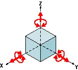
The Locating Process: 3-2-1 Method
We have two objectives when mounting a part in a fixture for machining:
1. Accurately position the part at the desired coordinates.
2. Restrict all six degrees of freedom so that the part cannot move.
A widely used method of accomplishing these two objectives uses the 3-2-1 principle, so-called because it entails three steps that employ three, then two, then one fixed points of known location. Since that adds up to six fixed points, it’s also known as the six point method.
In the three steps of the 3-2-1 method, three mutually perpendicular planes, called datum planes, are introduced, one at each step. These three planes define the workpiece position, and together with opposing clamping forces fully constrain the part. Let’s take a look at the details of the 3-2-1 method.
First Plane
Geometry tells us that three points are required to define a plane. This is the "3" in 3-2-1. So, three specific points are used to define the first plane. Fewer than three points cannot define a plane, and in the real world dimensional tolerances mean that four or more points will not be coplanar. A real-world, less than ideally perfect part placed on four or more reference points will, in fact, rest on only three of the points due to its less than perfect surface. Different parts may rest on different combinations of three points, resulting in variation between finished parts. A stool can be used to illustrate this concept. A two-legged stool would certainly be unstable. A three-legged stool sits rock-solid. A four-legged stool is often found to rock. In the illustration, a three dimensional part, represented by a cube, is placed on a datum plane defined by three support points. The part’s six degrees of freedom have now been reduced to three. It can still move along the X or Y axes, and it can still be rotated about the Z axis. (The part cannot move along the Z axis because it is held against the plane by clamping force.
Recommendation for First plane
- Use the largest surface of the part for the first ("primary") reference plane.
- Position the three support points as far apart as possible.
- If more than three support points are required to prevent deflection, make the additional points adjustable
Second Plane
A second plane, if it is perpendicular to the first, can be defined by two points, the "2" in 3-2-1. The part is now constrained to one degree of freedom: movement along the Y axis. (The part cannot move along the X or Z axes because it is held against the planes by clamping force.)

Third Plane
A third plane, if it is perpendicular to both of the first two planes, can be defined by one point, the "1" in 3-2-1. The part is now entirely constrained. It cannot move along or rotate about the X, Y, or Z axes. (Remember that the part is held against each of the three planes by clamping force.)
Recommendation for Third plane
- If more than one support point is required to prevent deflection, make the additional points adjustable.
Machined is Best
It’s best if the workpiece surfaces intended to contact the support points are machined. Cast surfaces are usable, but then tend to create tolerance problems. Machined holes are the number one choice. Two machined holes can be used to eliminate all but one degree of freedom.
Repeatability
Repeatability is a paramount concern. It means that each part should be nearly identical to each other part coming off the same fixture. "Nearly identical" actually has a specific, quantifiable meaning: key dimensions of all parts produced on the same fixture must fall within defined tolerances.
In order to stay within tolerances, it’s best if the workpiece surfaces intended to contact the support points are machined. Cast surfaces are usable, but they tend to create tolerance problems. Machined holes are the number one choice, because two machined holes can be used to eliminate all but one degree of freedom.
The next best feature to use for consistent locating is machined surfaces at right angles. The "machined surface" desired here can simply be a tab or small flat specifically included for locating purposes.
Repeatability is achieved through application of the 3-2-1 method to the three aspects of the locating process:
1. Supporting
2. Locating (positioning)
3. Holding
Supporting
- The part is supported from "below" with reference to the Z axis. (Introduction of the first reference plane.)
- Gravity positions the part against the support locator.
- Provide adjustable auxiliary support points as needed to prevent deflection.
- Vertical location with respect to the fixture is now established
- The part is positioned horizontally, in the X-Y plane. (Introduction of the second and third reference planes.)
Holding
- The part is clamped against fixed locators. Therefore, a known and unvarying position of the part is maintained with respect to the X, Y, and Z axes.
- One strap clamp or clamp arm will restrict the workpiece in three dimensions due to friction between the workpiece and clamp. However, friction alone may not be enough to prevent the workpiece from moving during machining.
- Cutting forces will not move a properly supported and clamped part.
Locating
- The part is positioned horizontally, in the X-Y plane. (Introduction of the second and third reference planes).
5.Elaborate types of BIW Stations?
An assembly line is a process in which car panel/car body parts are joined as the semi finished assembly moves from one station to another station until the final product is produced.
In the process of joining in assembly line , panels are moved from one section to another sections.Those sections are called Station.
In BIW fixture designing we have various stations which are used to locate the panels so that joining processes can be done.
Some of these stations are:
- Geo Station
- Respot Station
- Pedestal Weld/Rivet
- Loading Station
- Buffer Station
- Marriage station
- Sealing station
- Curing station
1. Geo station:
In this station geometry of two parts are fixed. it can be either using welding or riveting . In this station precision and geomatry of the finished product is defined Locating pins have closer tolerence of 0/-0.15.
Suppose the hole dia of panel is 16mm then the pin dia minimum can be 15.85.
Diameter of locating pins should be lesser than the panel hole dia. So Tolrence in locating pin is given in negative value.
2. Respot Station :
Once product comes out of the Geo Station and there are left out spots where spot welding or riveting is to be done. then it is moved to another station , that station is called Re-spot station.
These left out spots may be the due to clamp plan, cycle time,robot reach ability or any other various reasons.
In this station pins ahve tolrence upto 0/-0.28.
3. Pedestal Station :
In this station , Pedestal gun is mounted on a tool and panel is manipulated manually or by robot to weld the panels.
Pedestal station is generally a Re spot station.
Re spot station and Pedestal station, both perform same kind of operation . but to decide whether to go for pedestal or a re-spot station some parameters needs to consider like cycle time, floor space, no. of welds, clamp plan, or size of the panel.
4. Loading Station :
This station is used for loading of panel and same station is used to change the orientation of the if it is required in the upcomin station.
Sometime this station is used when Robots are unable to transfer panel from one station to another.
5. Buffer Station :
This station is used to make the balance between the process.
Some stations carry out procees in lesser time as compared to their respective stations.In that case panels can be stored in one sation so that assembly line process remains smooth.
6. Sealer Station :
In this station Sealant application is carried out.This process can be carried out manually or by using robots. Sealer is used in between two panels so that panels do not flatter due to friction.
7. Marriage Station :
In this Station inner and outer panels are joined. In this station to avoid the impression on the outer panel(A class surface), copper strips are used in betweenn the weld tip and A-class surface.
8. Curing Station :
In this Station product recieved after sealing application, is kept idle at ambient temperature, which allows sealent to get dry with better bonding between the panel.
6.What are the basic terminologies used in the BIW fixture?
The basic terminologies used in BIW are
-
Shim
Shim is a set of thin plates (2 mm, 1mm, 0.5 mm, 0.25mm) that are used to adjust the gap or used for a better fit. Shimming can be of thickness 5mm, 8mm, or 10mm. in case no proper fitting between mylar and Panel due to manufacturing errors then this error can be removed using shims. Shims are placed in the carline position so that gap can be adjusted in the required direction like X, Y, or Z.There are three types of shimming. These are one-way, two-way, and three-way shimming.
Number of shimming depends upon the NC cut angle and PIN angle with the car line.
If NC cut is less than 15 deg then mylar will have one-way shimming.
If NC cut is more than 15 deg in one direction then mylar will have a 2-way direction shimming
If NC has more than 15 deg angle in two directions then mylar will have 3-way directional shimming.
But in the case of pins, this case is a bit different. If the pin is on the angle with respect to the carline and that angle is more is not more than 15 deg then the pin will have 2-way directional shimming, if Pin’s angle is more than 15 deg in any direction then 3 shimming will be used.
- Mylar
MYLAR is one kind of block that touches the panel and holds or clamps the panel. Mylars are always designed in CAR LINE. Mylar is also called NC(Numerically Controlled)Block. Mylars are mounted on any block or plate with Shimming, So that height of mylar can be adjusted accordingly at the assembly level. For ‘A’ class surfaces Nylon mylars are used. So that surface can be saved from scratches. Shimming can be 1 directional, 2 directional, or 3 directional as per the NC cut.
- Pins
Pins are used to locking the rotational movement of the panel. Generally there two types of Pins, one is Round Pin and another one is a Diamond pin. We use two and three-directional shimming for pins as per the angle of the pin w.r.t. the carline. In some cases, we use a collared pin, when the pin is supposed to support the panel as well. For this kind of pin, we provide 3 way shimming irrespective of pin angle to the carline.
- Blade
The plate which connects Riser to the Clamp cylinder is named Blade. This plate plays an important role in building the unit. The plate can be of any shape. But we need to keep in mind that the plate should be as compact as possible.
- L block
A plate shaped as L is called an L block. This part is used as a connection between mylar and Blade. Generally, L blocks are used to provide shimming. It is not necessary that L blocks are only used for shimming, its uses changes as per the requirements, At some places, it is used just to connect one part to another. Similar to the L block one more block is used which is in the shape of T. So this block is called a T Block.
- Pin block
Pin Block is also called Pin Retainer. This block holds the pin and restricts the rotational motion of the pin. Pin Block can be either manufactured one or Standard.
- Riser
The part which is mounted on the base plate and holds a clamp or pin cylinder on it, is called Riser. Riser can be Standard Part or manufactured part, it varies from project to project. A riser can be a Single part or welded part. Standard risers also have various shapes and sizes.
- Weldment
Weldment is the assembly of two or more parts that are joined by welding. To make a weldment it is the thumb rule to have a 5 mm overlay on each other plates so that space can be provided for welding. A weldment can be of any size and any number of plates.