Week 1:- Introduction to BiW and Fixtures Challenge
What Is Biw
Why is it called BIW?
, A folk etymology for “body in white” is the appearance of a car body after it is dipped into a white bath of primer (undercoat paint)— despite the primer’s actual gray color.
Furthermore, What is BIW in automotive industry?,
4 Body-in-White (BiW) Body-in-white (BiW) is the name given to a car body’s sheet when all its components—barring moving parts (e.g., hoods, fenders, etc.), trims (e.g., glass, seats, etc.), or chassis subassemblies—have been welded together.
Finally, What is BIW & define its parts?, 1) What is BIW & define its parts? Body in white (BIW) refers to the stage in the automobile manufacturing in which a car body’s components have been joined together, using one or a combination of different techniques: welding (spot, MIG/MAG), riveting, clinching, bonding, laser brazing etc.
What are the types of BIW?
BIW structures can be divided into following sub-structures:
- Underbody structure.
- Front End Structure.
- Body side structure.
- Closures.
- Roof.
What does BIW mean?
4 Body-in-White (BiW) Body-in-white (BiW) is the name given to a car body’s sheet when all its components—barring moving parts (e.g., hoods, fenders, etc.), trims (e.g., glass, seats, etc.), or chassis subassemblies—have been welded together.
What is BIW in manufacturing?
Destaco products play a significant role in the automotive Body-in-White (BIW) manufacturing process. At this automotive manufacturing stage, the plain, non-painted, steel frame components are welded and assembled together to form the vehicle’s basic structure.
What does BIW mean in automotive?
Destaco products play a significant role in the automotive Body-in-White (BIW) manufacturing process. At this automotive manufacturing stage, the plain, non-painted, steel frame components are welded and assembled together to form the vehicle’s basic structure.
What is BIW process?
Body in white (BIW) is the stage in automobile manufacturing in which a car body’s frame has been joined together, that is before painting and before the motor, chassis sub-assemblies, or trim (glass, door locks/handles, seats, upholstery, electronics, etc.) have been integrated into the structure.
What is BIW system?
4 Body-in-White (BiW) Body-in-white (BiW) is the name given to a car body’s sheet when all its components—barring moving parts (e.g., hoods, fenders, etc.), trims (e.g., glass, seats, etc.), or chassis subassemblies—have been welded together.
What are the basic terminologies used in the BIW Fixture?
In this section, we will learn about some basic manufacturing parts, which are commonly used in the BIW fixture design. Very commonly used parts are Mylar, Pin, Blade, L Block, Pin Block, Riser, Weldment, etc.
Before we go to these parts we should know about shimming and should know how it works.
Shim is a set of thin plates (2 mm, 1mm, 0.5 mm, 0.25mm) that are used to adjust the gap or used for a better fit. Shimming can be of thickness 5mm, 8mm, or 10mm. in case no proper fitting between mylar and Panel due to manufacturing errors then this error can be removed using shims. Shims are placed in the carline position so that gap can be adjusted in the required direction like X, Y, or Z.
There are three types of shimming. These are one-way, two-way, and three-way shimming.
Number of shimming depends upon the NC cut angle and PIN angle with the car line.
If NC cut is less than 15 deg then mylar will have one-way shimming.
If NC cut is more than 15 deg in one direction then mylar will have a 2-way direction shimming
If NC has more than 15 deg angle in two directions then mylar will have 3-way directional shimming.
But in the case of pins, this case is a bit different. If the pin is on the angle with respect to the carline and that angle is more is not more than 15 deg then the pin will have 2-way directional shimming, if Pin’s angle is more than 15 deg in any direction then 3 shimming will be used.
MYLAR :
MYLAR is one kind of block that touches the panel and holds or clamps the panel. Mylars are always designed in CAR LINE. Mylar is also called NC(Numerically Controlled)Block. Mylars are mounted on any block or plate with Shimming, So that height of mylar can be adjusted accordingly at the assembly level. For ‘A’ class surfaces Nylon mylars are used. So that surface can be saved from scratches.
Shimming can be 1 directional, 2 directional, or 3 directional as per the NC cut.
PIN:
Pins are used to locking the rotational movement of the panel. Generally there two types of Pins, one is Round Pin and another one is a Diamond pin. We use two and three-directional shimming for pins as per the angle of the pin w.r.t. the carline. In some cases, we use a collared pin, when the pin is supposed to support the panel as well. For this kind of pin, we provide 3 way shimming irrespective of pin angle to the carline.
BLADE :
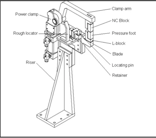
The plate which connects Riser to the Clamp cylinder is named Blade. This plate plays an important role in building the unit. The plate can be of any shape. But we need to keep in mind that the plate should be as compact as possible.
L BLOCK :
A plate shaped as L is called an L block. This part is used as a connection between mylar and Blade. Generally, L blocks are used to provide shimming. It is not necessary that L blocks are only used for shimming, its uses changes as per the requirements, At some places, it is used just to connect one part to another. Similar to the L block one more block is used which is in the shape of T. So this block is called a T Block.
PIN BLOCK :
Pin Block is also called Pin Retainer. This block holds the pin and restricts the rotational motion of the pin. Pin Block can be either manufactured one or Standard.
RISER :
The part which is mounted on the base plate and holds a clamp or pin cylinder on it, is called Riser. Riser can be Standard Part or manufactured part, it varies from project to project. A riser can be a Single part or welded part. Standard risers also have various shapes and sizes.
WELDMENT :
Weldment is the assembly of two or more parts that are joined by welding. To make a weldment it is the thumb rule to have a 5 mm overlay on each other plates so that space can be provided for welding. A weldment can be of any size and any number of plates.
BIW FIXTURE BASIC PARTS TERMINOLOGY
- MYLAR : MYLAR is one kind of block that touches the panel and holds or clamps the panel. …
- PIN: Pins are used to locking the rotational movement of the panel. …
- BLADE : The plate which connects Riser to the Clamp cylinder is named Blade. …
- L BLOCK : …
- PIN BLOCK : …
- RISER :
-
In this section, we will learn about some basic manufacturing parts, which are commonly used in the BIW fixture design. Very commonly used parts are Mylar, Pin, Blade, L Block, Pin Block, Riser, Weldment, etc.
Before we go to these parts we should know about shimming and should know how it works.
Shim is a set of thin plates (2 mm, 1mm, 0.5 mm, 0.25mm) that are used to adjust the gap or used for a better fit. Shimming can be of thickness 5mm, 8mm, or 10mm. in case no proper fitting between mylar and Panel due to manufacturing errors then this error can be removed using shims. Shims are placed in the carline position so that gap can be adjusted in the required direction like X, Y, or Z.
There are three types of shimming. These are one-way, two-way, and three-way shimming.
Number of shimming depends upon the NC cut angle and PIN angle with the car line.
If NC cut is less than 15 deg then mylar will have one-way shimming.
If NC cut is more than 15 deg in one direction then mylar will have a 2-way direction shimming
If NC has more than 15 deg angle in two directions then mylar will have 3-way directional shimming.
But in the case of pins, this case is a bit different. If the pin is on the angle with respect to the carline and that angle is more is not more than 15 deg then the pin will have 2-way directional shimming, if Pin’s angle is more than 15 deg in any direction then 3 shimming will be used.
MYLAR :
MYLAR is one kind of block that touches the panel and holds or clamps the panel. Mylars are always designed in CAR LINE. Mylar is also called NC(Numerically Controlled)Block. Mylars are mounted on any block or plate with Shimming, So that height of mylar can be adjusted accordingly at the assembly level. For ‘A’ class surfaces Nylon mylars are used. So that surface can be saved from scratches.
Shimming can be 1 directional, 2 directional, or 3 directional as per the NC cut.
- A) NC/Mylars/Fingers
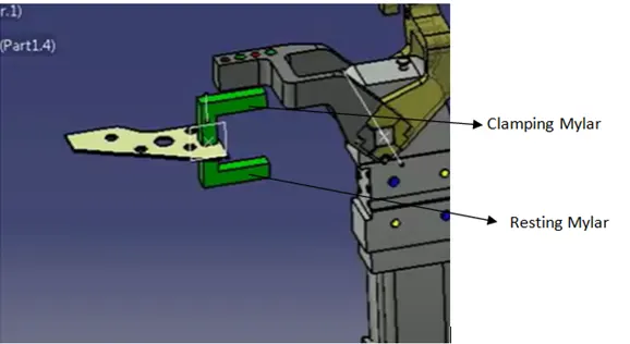
- Mylars are the component that holds the panel while These are placed from topside & from the bottom side also. The top side Mylars called Clamping Mylars & the bottom side Mylars called Resting Mylars. Every clamping Mylars have resting Mylars. It doesn't allow deformation of the part due to welding stresses.
B) Principle locating point (PLP)
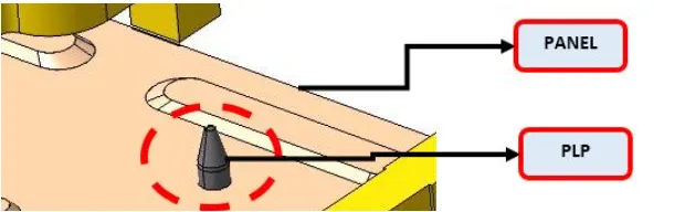
- These are the points that are used for the accurate location of the part to maintain the geometry of the part. There is lots of holes on the panel which are not accurate due to stamping operation. The PLP are defined in the drawing. The positional dimensions or relative dimensions are very precise in stamping & in fixtures also.
PIN:
Pins are used to locking the rotational movement of the panel. Generally there two types of Pins, one is Round Pin and another one is a Diamond pin. We use two and three-directional shimming for pins as per the angle of the pin w.r.t. the carline. In some cases, we use a collared pin, when the pin is supposed to support the panel as well. For this kind of pin, we provide 3 way shimming irrespective of pin angle to the carline.
BLADE :
The plate which connects Riser to the Clamp cylinder is named Blade. This plate plays an important role in building the unit. The plate can be of any shape. But we need to keep in mind that the plate should be as compact as possible.
L BLOCK :
A plate shaped as L is called an L block. This part is used as a connection between mylar and Blade. Generally, L blocks are used to provide shimming. It is not necessary that L blocks are only used for shimming, its uses changes as per the requirements, At some places, it is used just to connect one part to another. Similar to the L block one more block is used which is in the shape of T. So this block is called a T Block.
PIN BLOCK :
Pin Block is also called Pin Retainer. This block holds the pin and restricts the rotational motion of the pin. Pin Block can be either manufactured one or Standard.
RISER :
The part which is mounted on the base plate and holds a clamp or pin cylinder on it, is called Riser. Riser can be Standard Part or manufactured part, it varies from project to project. A riser can be a Single part or welded part. Standard risers also have various shapes and sizes.
WELDMENT :
Weldment is the assembly of two or more parts that are joined by welding. To make a weldment it is the thumb rule to have a 5 mm overlay on each other plates so that space can be provided for welding. A weldment can be of any size and any number of plates.
What does BIW mean in a text?
BIW
| Acronym | Definition |
| BIW | Best in the World |
| BIW | Building Information Warehouse |
| BIW | Ben Ik Weer (Dutch: I’m Back) |
| BIW | Built in Wardrobe (rental properties) |
What does BIW mean in physical therapy?
O.W.; BIW; TIW: once a week; twice a week; three times a week.
What does bow acronym mean?
Basic Operating Weight (aviation) BOW. Back of Wall. BOW. Bill of Work.
What does TIW mean in text?
TIW
| Acronym | Definition |
| TIW | There I Was… (slang; an embellished story follows) |
| TIW | Triple-Insulated Wire |
| TIW | The Insurance Workplace |
| TIW | Texas Iron Works (Waco, TX) |
F)Â Rough locators
- The operator can place the part in the wrong orientation The rough locator will work as a guide while placing the part in the fixture & the part will be loaded in the desired orientation. It is a part of foolproofing.
G) Hardware
- Hardware is like the Hex head bolts, Allen Bolts, Hex nuts, Spring washers, Self-locking nuts
H) CMM
- CMM stands for coordinate measuring machine. It is a device that measures the geometry of physical objects by sensing discrete points on the surface of the object with a probe. It generates a report by comparing the data with the CAD file data.
I)ÂUnit
- The fixture is the assembly of different types of units to form a part. There are different units like pin unit, base unit, clamping unit, etc.
J) Number plates
- The number plate is the aluminum embossed plate placed on each unit for easily recognizing the part unit.
K) Nameplate
- The data like manufacturing company name, fixture type, Fixture weight is embossed on the plate & joined to the fixture.
L) Clamp Arm
- The clamp arm is the part of the clamp unit which moves an Over clamp arm the Mylars are mounted.
M) Pivot
- It is an axis about which the clamp arm will rotate
N) Class A Surface/Skin surface
- The outer panels of the car like a hood, door, backdoor, fender, roof are visible to the customer.
- The outer panels should be aesthetically very good. No scratches or dent is acceptable over it.
- While designing the fixture to the skin surface the clamping material should be soft, so that it could not able to left any impression or dent over the skin. generally, nylon or PU material is used for clamping purposes.
O)Reed switches & sensors
- These are the electric components used in automated The reed switch is an electrical switch operated by an applied magnetic field. The detects the panel is loaded or not is done by sensors.
What is BIW product design?
Body in White (B.I.W.) refers to the welded sheet metal components which form the vehicles structure to which the other components will be married, i.e., engine, chassis, exterior and interior trim. Services: Welding fixture designing for complete Body shell (Side body, under body, Enclosures etc.)
What is BIW in vehicle?
Body-in-white (BiW) is the name given to a car body’s sheet when all its components—barring moving parts (e.g., hoods, fenders, etc.), trims (e.g., glass, seats, etc.), or chassis subassemblies—have been welded together.
What is the importance of an automotive BIW?
The dynamic behavior of a body-in-white (BIW) structure has significant influence on the noise, vibration, and harshness (NVH) and crashworthiness of a car.
What is BIW process planning?
In car body manufacturing the individual, pre-formed sheet parts of the car body, i.e. floor elements and parts for the engine cavity, side walls, roof and door components are put together. … TECOSIM engineers support different services for the process planning in the area of car body manufacture (BIW).
What is BIW automation?
Body in white (BIW) refers to the stage in the automobile manufacturing in which a car body’s components have been joined together, using one or a combination of different techniques: welding (spot, MIG/MAG), riveting, clinching, bonding, laser brazing etc. …
What is meant by BIW fixture?
Body in White (B.I.W.) refers to the welded sheet metal components which form the vehicles structure to which the other components will be married, i.e., engine, chassis, exterior and interior trim.
Fundamentals of BIW Stamping Die Design
Stamping is the most common method of producing metal parts in the automotive industry because of its high production rate and low cost. Stamping die design is the preliminary phase in stamping tool and die making and is carried out as soon as the component design is finished. During the design phase, the necessary manufacturing methods, as well as the sequence and number of production steps, are established in a processing plan. In this plan, the availability of machines, the planned production volumes of the part, and other boundary conditions are taken into account. The aim is to minimize the number of dies to be used while keeping up a high level of operational reliability. The parts are greatly simplified right from their design stage by close collaboration between the Part Design and Production Departments in order to enable several forming and related blanking processes to be carried out in one forming station. Obviously, the more operations which are integrated into a single die, the more complex the structure of the die becomes. The consequences are higher costs, a decrease in output, and lower reliability.
The process of die design for each part begins with the sketching of the processes of the part, which will be brought separately in the compartments of a table, called the process sheet. Each one of the processes generally includes one of the principal operations such as cutting, forming, drawing, or trimming. The process sheet should contain the processes. Which form flat sheet metal to a fully formed part. Following requirements and information should be included in the process sheet:
Tool number, arranging from 1 to n (n is the last tool number).
Operation number shows the order of operations added to an "OP". e.g. OP 05. OP 10. OP 20, etc. As a rule, it. should be named the first operation to "OP10" for the"'Draw" operation. However, If a blanking operation needs before the OP10. it will add an “OP05" e.g. for a blank operation. In the case of needs to any other operations between the regular operations, it should be used a median operation name for them. For example OP05. Op10, Op15, Op20,Op25,Op30. Op40, etc.
The operation name is the name of an operation in which one of the principal operations such as Draw, form. Trim, Re-strike, etc. is to be done on the panel,
Tool size is general dimensions of tool (width, length, and height), used for choosing the appropriate press and to an estimation of the total weight of the tool.
The tonnage of the press (or press force) is the amount of minimum required force to apply operation easily. used for choosing an appropriate press.
Die specifications specify whether die should produce right hand or left-hand part or both.
The part number is an identifier for the technical number of parts.
Thickness is the thickness of raw sheet metal.
Approver Identifications with its date should contain the signature of drafter, checker, or approver with printing date.
Page number specifies the number of sheets attached.
Material specifies the raw sheet metal material used in the operations.
Blank areas are used to sketching operation processes,
The direction of feeding and pressing should be shown.
In order to preview the general concepts of die design, a detailed die layout drawing of the processes should be prepared completely before die design. Each die layout drawing should include the following information:
Title Block should contain general information such as part name, part number, tool name, tool operation number. material and thickness of sheet metal. Toolmaker name and its logo, signature of drafter, checker, and approver with printing appropriated date. Scale, sheet number, and other needed information should be added too. Title block should be placed on the right hand lower corner
Operations side Boxes should be ordered upward vertically above the title block which contains concept sketches brought from the process sheet. The following information should be included in the side boxes:
a)Operation sketch showing the operation in which one of the principal operations. such as drawing, trimming, flanging, piercing, cam pierce or other operations will be applied. In addition, the illustration of press direction and feeding the panel should be shown,
b)In order to obtain the best result in the forming of the part during the stroke of the tool, the suitable rotation angle of punch and die surfaces should be defined based on the rotation angle of CAD data during the face design if needed. In other words, the draft angles should be considered regarding the ease of ejection of the panel in direction of the press.
c)Operation name according to the assumed operations should be notified
d)Operation number according to the order number of the operations should be notified.
e)Press tonnage according to the estimated force for the assumed operations should be shown in the appropriate box.
The modifications table shows the modifications generated and announced by the client.
Notes area should be added if there is an important notification to the toolmaker.
The line type table shows the type of the used borderlines of each one of the operations with a specific pattern separately.
the procedure of loading and unloading the panel from the die, whether it is manual or automatic. should be specified.
Plan view of the panel is a single plan of the panel showing the operations from the first to the final, Each one of the operations should be defined using a specific patterned line in a legend table. The following items should be specified on the plan view.
WELDMENT :
Weldment is the assembly of two or more parts that are joined by welding. To make a weldment it is the thumb rule to have a 5 mm overlay on each other plates so that space can be provided for welding. A weldment can be of any size and any number of plates.
with fixture -I in IGRIP environment 5.1.3. Kinematics definition
FIXTURE :
1 Introduction
In most of manufacturing processes1
, the product should be fixed securely and accurately
in front of the machine in order to desire task can be accomplished. This fixing duty is the
main role of fixtures in the industry. Fixture designing is an inevitable common task of
both design and process planning engineers and demands considerable work, time,
energy, and money. Traditional disciplines suggest the order of part design, fixture design,
and then going down to manufacture planning procedure; which means that in ‗work
holding problem‘, the part, and not the process is the primary consideration (1). However,
this method is under serious debate recently due to variety of products and need for
accurate process planning far in advance. This report will describe the need for opening a
new horizon in this topic.
1.1 Flexible Manufacturing and Flexible Plants
Presence of robots as a resource to the manufacturing process has been tied with
the term Flexible Manufacturing Systems (FMS). According to the definition (2)
FMS is:
―A group of machining, assembly or general fabrication stations, each supplied with
components by a variable mission conveyor system, and all controlled by computer‖.
Or (3)
“The ability of a manufacturing system to adapt to changes in environmental conditions
and in the process requirements”.
With the aid of FMS, manufacturers are now capable of changing their product or
manufacturing process as fast and as cheap as possible. By the way, this flexibility
can only be obtained by increasing the complexity of the system; which can be
called a drawback on the FMS approach. Due to development of simulation
techniques, the new tools helped engineers to overcome this complexity and so
increasing the certainty and predictability of the manufacturing systems. In
discussion with industrial partners in this project, it is observed that in most cases,
the terms simulation and modelling if used together, can cover a wide range of the
product development stage, from the part designing in CAD systems, to the
process, line and manufacturing simulation. Today, these new approaches lead the
industry to the new generation of simulation tools called ―Product Lifecycle
1
Example of processes that utilizing fixture: Assembling, Boring, Broaching, Drilling, Forming, Gauging,
Grinding, Heat Treating, Honing, Inspecting, Lapping, Milling, Planning, Sawing, Shaping, Stamping,
Tapping, Testing, Turning, Welding, Robotic Spot Welding, Robotic Painting, Robotic Gluing, etc.
A device which is used to hold, locate and support the component in the manufacturing industry is called fixture. Fixtures ensure to provide the stability to the part when any process is being done on that part. That process can be welding, riveting, grinding, drilling etc. In BIW fixture design Fixture works on 3-2-1 principle.
WHAT IS 3-2-1 PRINCIPLE
Basically 3-2-1 principle is used to lock all six degree of freedom.
The 3-2-1 principle is a Component holding principle where three pins are located on the 1st principle plane, i.e. either XY, YZ, ZX. And two pins are located on the 2nd plane which is perpendicular to the 1st plane, and at last one pin on the plane which is mutually perpendicular to the 1st and 2nd planes.By using this method Componet can be arrested in all six degrees of freedom.
Assembly Line :
An assembly line is a process in which car panel/car body parts are joined as the semi finished assembly moves from one station to another station until the final product is produced.
In the process of joining in assembly line , panels are moved from one section to another sections.Those sections are called Station.
In BIW fixture designing we have various stations which are used to locate the panels so that joining processes can be done.
Some of these stations are:
- Geo Station
- Respot Station
- Pedestal Weld/Rivet
- Loading Station
- Buffer Station
- Marriage station
- Sealing station
- Curing station
1. Geo station:
In this station geometry of two parts are fixed. it can be either using welding or riveting . In this station precision and geomatry of the finished product is defined Locating pins have closer tolerence of 0/-0.15.
Suppose the hole dia of panel is 16mm then the pin dia minimum can be 15.85.
Diameter of locating pins should be lesser than the panel hole dia. So Tolrence in locating pin is given in negative value.
2. Respot Station :
Once product comes out of the Geo Station and there are left out spots where spot welding or riveting is to be done. then it is moved to another station , that station is called Re-spot station.
These left out spots may be the due to clamp plan, cycle time,robot reach ability or any other various reasons.
In this station pins ahve tolrence upto 0/-0.28.
3. Pedestal Station :
In this station , Pedestal gun is mounted on a tool and panel is manipulated manually or by robot to weld the panels.
Pedestal station is generally a Re spot station.
Re spot station and Pedestal station, both perform same kind of operation . but to decide whether to go for pedestal or a re-spot station some parameters needs to consider like cycle time, floor space, no. of welds, clamp plan, or size of the panel.
4. Loading Station :
This station is used for loading of panel and same station is used to change the orientation of the if it is required in the upcomin station.
Sometime this station is used when Robots are unable to transfer panel from one station to another.
5. Buffer Station :
This station is used to make the balance between the process.
Some stations carry out procees in lesser time as compared to their respective stations.In that case panels can be stored in one sation so that assembly line process remains smooth.
6. Sealer Station :
In this station Sealant application is carried out.This process can be carried out manually or by using robots. Sealer is used in between two panels so that panels do not flatter due to friction.
7. Marriage Station :
In this Station inner and outer panels are joined. In this station to avoid the imprssion on the outer panel(A class surface), copper strips are used in betweenn the weld tip and A-class surface.
8. Curing Station :
In this Station product recieved after sealing application, is kept idle at ambient temperature, which allows sealent to get dry with better bonding between the panel.