Week 1 : Exploring the GUI of GT-POWER
Modules Available with GT-SUITE:
- Air Conditioning Modelling and Waste Heat Recovery- Solve problems related to two phase applications by providing instructions to build components of an air conditioning system and also Heat Recovery in different types of cycles like Rankine Cycle. Also Refrigerant system can also be designed.
- Acoustics-Analyze a signal in the time domain by transforming it to the frequency domain and to calculate the frequency response of various systems in the frequency domain.
- Aftertreatment- Capability to model numerous exhaust aftertreatment components and complete aftertreatment systems. The methodology is highly flexible and gives the user complete control over the reaction kinetics being used. The kinetics are NOT hard-wired, nor do they require the user to modify user subroutines or use a compiler.
- Thermal Management- Can be used to integrate all of the activities related to heat management to meet design objectives such as engine durability, emissions, fast warm-up, passenger cabin heating, component sizing and specification, and system control.
- Cranktrain Application- Aimed at simulation of various dynamics, vibration and tribological phenomena resulting from primary motions of moving parts (crankshaft, connecting rods and pistons) in multi-cylinder engines.
- Engine Performance- It is suitable for analysis of a wide range of issues related to vehicle and engine performance. This manual focuses on engine applications. The engine performance is designed for steady-state and transient simulations and can be used for analyses of engine and powertrain control.
- Fuel Injection- Modeling fuel injection and general hydraulic components and systems. It is capable of modeling the coupled behavior of hydraulic and mechanical components. In the context of fuel systems, it is applicable to any diesel or gasoline system, including both common rail and unit pump systems.
- Geartrain, Chain and Belt Drive- It transfer rotational motion and power between mechanical 1-D rotational/torsional systems. They can also be used to achieve a desired kinematic speed ratio, as well as torque reduction. In engines, gear, chain or belt systems are used primarily as timing drives for subsystems such as mechanically actuated valvetrains and injections systems (via camshafts), and also to transmit power to auxiliary systems such as (oil, coolant etc.) pumps, superchargers or power turbines. The detailed dynamics of these systems are analyzed in order to ensure that their transmission, noise and vibration and durability characteristics meet acceptable design criteria.
- Lubrication- Modeling engine lubrication systems, using a compressible 1-D CFD solution that solves for mass, momentum, energy and species. The primary purpose of modeling a lubrication system is to predict flow rate and pressure distribution throughout the system.
- Optimization- Optimization is the process of maximizing or minimizing a model's output(s) (responses) by systematically changing one or more input variables (factors). An optimizer is an automated process that iteratively sets the input variables, runs the model, evaluates the model output(s), and changes the inputs again to achieve some optimization objective, or until some stopping criteria are met.
- Valvetrain- This is the core library for building multi-body dynamic (MBD) models of single valvetrain "branches" or entire valvetrain systems and camshafts, in which rigid- and/or flexible-body parts are connected by contact, joint, spring and damper.
- Driveline- Provides users with a set of standard driveline components and connections that can be used to construct various driveline layouts and configurations. There are only a few areas where the layout is fixed.
Time Control Flag
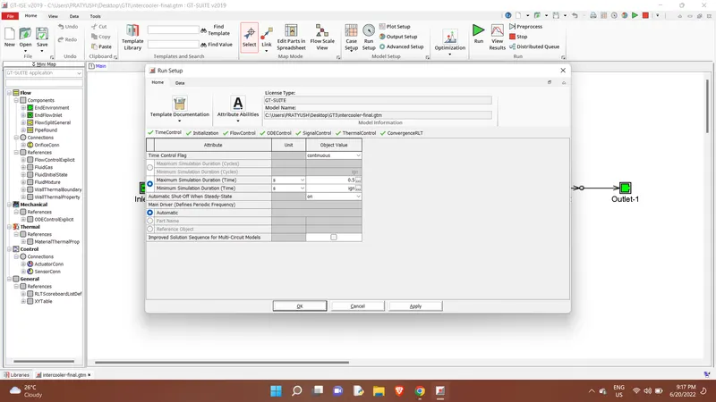
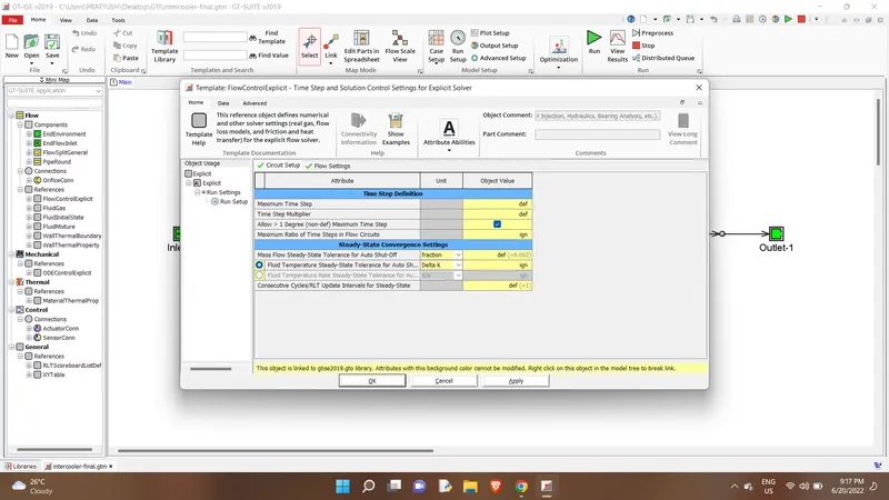
Time step and Solution Control
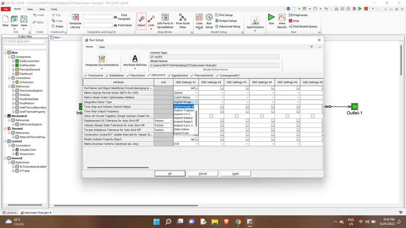
Integrator/solver Type
Intercooler Tutorial
Run Setup
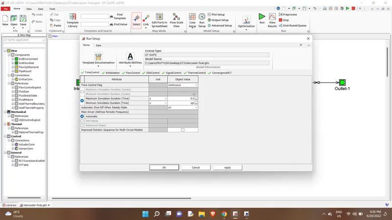
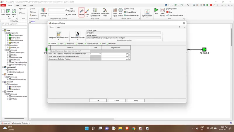
Advanced Setup
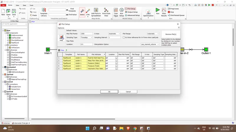
Plot Setup
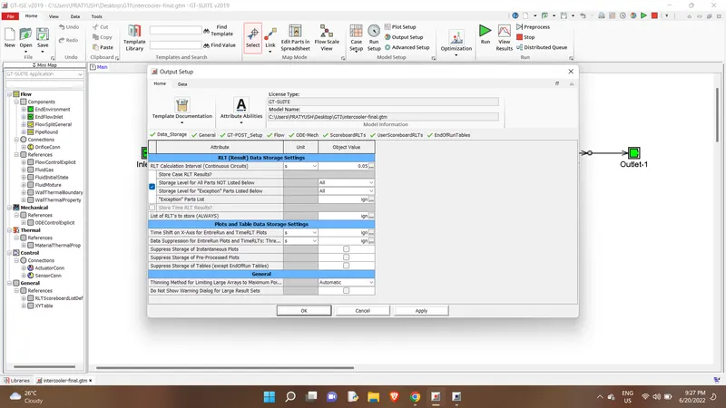
Output Setup
Layout
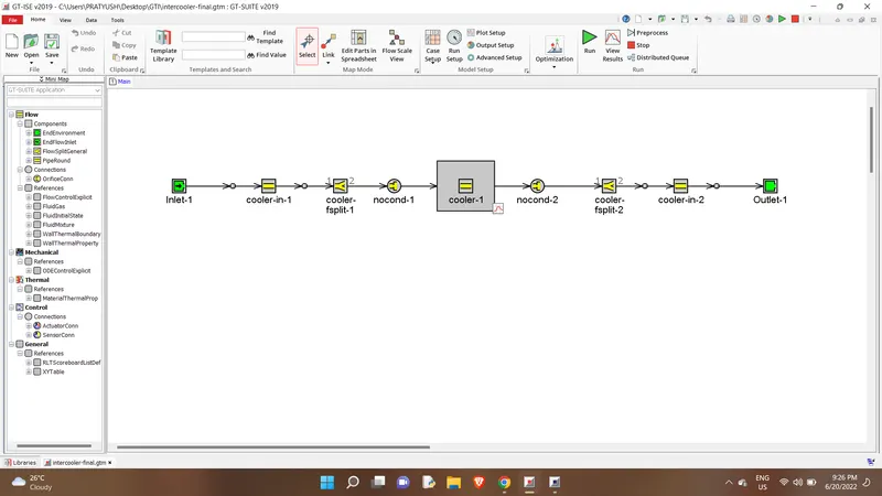
The followings changes have been made:
- Diameter of cooler inlet and outlet pipe= 50 mm
- Length of the CAC= 1000 mm
- Inlet mass flow rate = 1200 kg/ h at 100 degC
- Outlet pressure 2 bar at 30 deg C
Results:
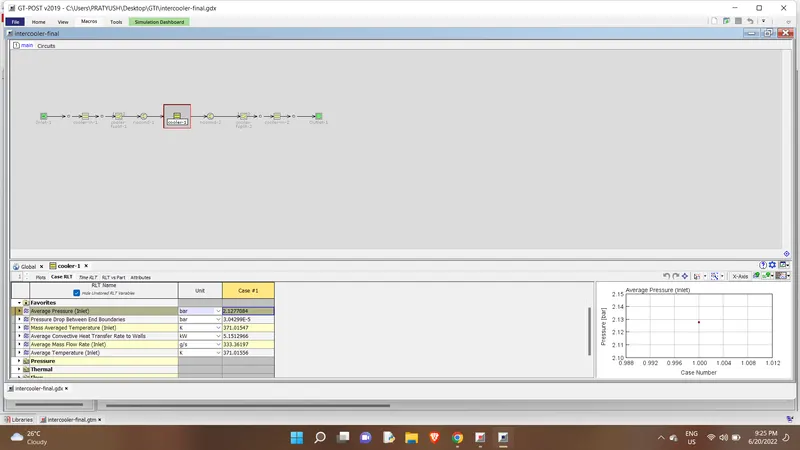
Average heat transfer at Charge air cooler (CAC):5.1512kW
pressure drop across CAC: 3.0429E-5 bar