Week 1 : Exploring the GUI of GT-POWER
Modules available in the Graphical User Interface of GT suite
GT Suite comprises of the following modules for GUI in version 2019
1. COOL 3D:- COOL 3D is a tool that can be used to buld 3D models of underhood thermal management flow systems that can be discretized and made into model files for use with GT SUITE. It provides the ability to build the model in a 3D environment so that the full details of the model can be included. It also includes sophisticated logic that is able to transforn 3D model into a model file that is compatible with the GT Suite software. COOL3D can be used ti build any flow system that contains only blockages fans, heat additions and heat exchangers.
2. DOE-Post:- Auto-DOE FT tool is a separate post processing application that can be launched from GT ISE. The basis of the AutoDOE-GT tool is a mathematical surface fit that is applied to the selected result data. Once the mathematical response surface has been calculated , it is possible to perform optimization or other investigations on the response surface very quickly. Auto-DOE has been replaced with a more modern DOE analysis tool
3. GEM3D:- GEM3D is a tool that can be used to build 3D models of flow, thermal and mechanical systems that can be discretized and made into model files for use with GT-Suite. It provides the ability to build the model in a 3D environment so that the full details of the model can be included.It also includes sophisticated discretization logic that is able to transform the 3D model into model file that is compatible with GT SUITE software.
4. GT POST:- GT Post is a plotting and a data handling tool used by GT Suite and consists of versatile functions.
5. GT-SPACECLAIM:- GT Spaceclaim is a tool that can be used to import CAD geometry of various formats and export them for discretization in GEM 3D. Building and exporting 3D models of flow is also possible.
6. VTDESIGN PREPROCESSOR:- VTDESIGN is a standalone interactive can/valvetrain/spring design tool supplied with GT Suite. VTDESIGN is composed of three main features including CAM design feature, Valvetrain Design feature and Spring Design feature.
2. Locate following settings
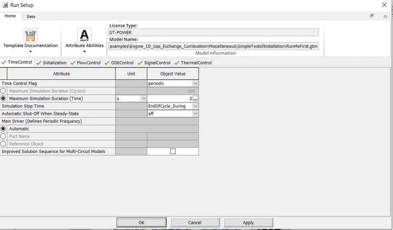
i) Time Control Flag
It is located in the Run Setup command under the Time Control tab and can be accessed as given below
Run setup-Time Control- Time Control Flag
ii) Time Step and Solution Control:-
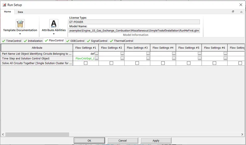
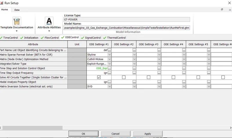
It is located in the Run Setup command under the Flow Control and ODE control tab and can be accessed as given below
Run setup-Flow Control- Time Step and Solution Control Object
Run setup-ODE Control- Time Step and Solution Control Object
iii) Integrator/Solver type:-
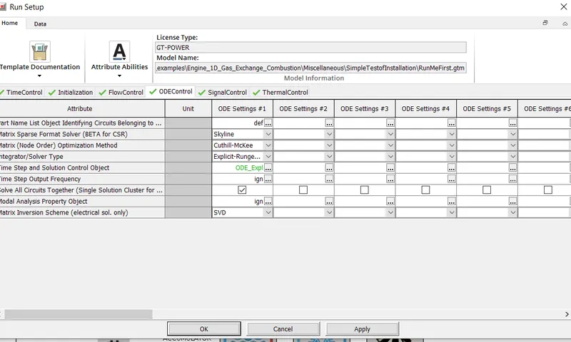
It is located in the Run Setup command under the ODE control tab and can be accessed as given below
Run setup-ODE Control- Integrator/Solver Type
3) Explore intercooler tutorial and note down all settings of
i) Run Setup:-
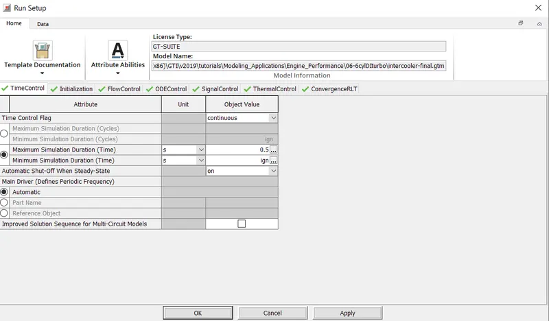
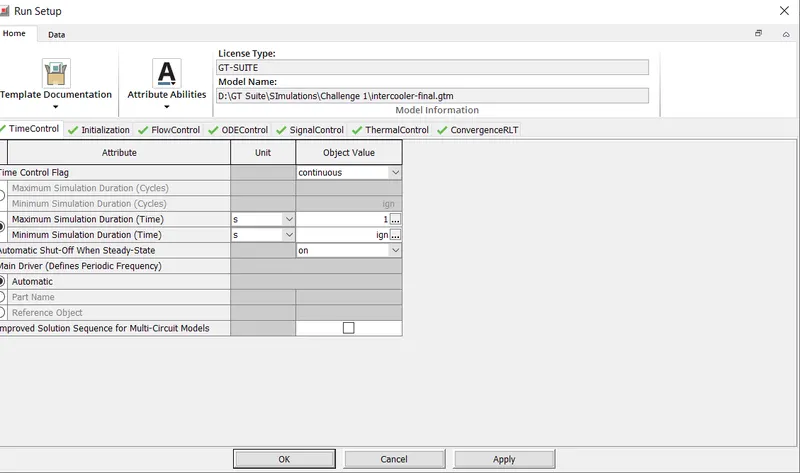
a) Time Control
- Time Control Flag- Continuous
- Maximum Simulation Duration (Time)- 0.5
- Minimum Simulation Duration - ign
-Automatic Shut off When Steady State -on
- Main Driver(Defines periodic Frequency)- Automatic
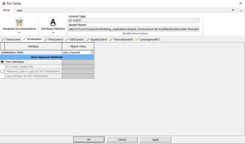
b) Initialization
- Initialization- user imposed
- User Imposed Methods- Part Attributes
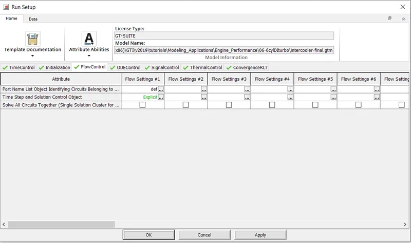
c) Flow Control
- Time Step and SOlution COntrol Object- Explicit (recommended for high frequency dynamics.
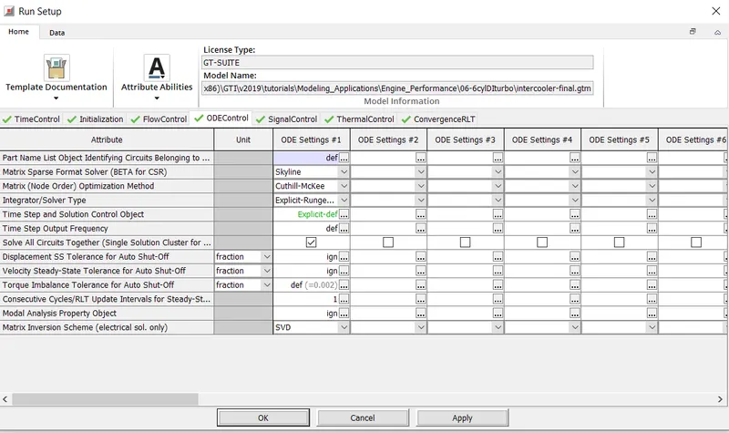
d) ODE Control
- Matrix Sparse FOrmat Solver (BETA for CSR) - Skyline
- Matrix Node Order Optimization Method- Cuthill-Mckee
- Integrator-/Solver Type- Explicit-Runge Kutta
- Time Step and Solution Control Object- Explicit def
e) For Signal Control, Thermal Control and Convergence RLT defaults have been retained
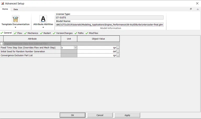
ii) Advanced setup
a) General:- Default retained
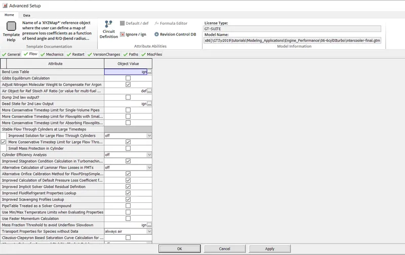
b) Flow:- Following Parameters have been checked
- Adjust Nitrogen Molecular Weight to Compensate for Argon
- More Conservatitve Timestep Limit for Large Flow through cylinders
- Improved Stagnation condition calculation in Turbomachine applications
- Alternative Orifice Calibration for Method for FlowPDropSimple Objects
-Improved calculation of Default Pressure Loss coefficient for diffusers
-Improved Implicit Solver global residual definition
- Improved Fluid Refrigerant properties Lookup
-Improved Scavenging profile lookup
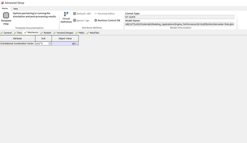
c) Mechanics:- Values set as shown below
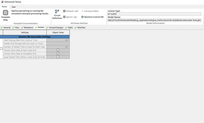
d) Restart
e) Version Changes:- Values selected as shown below
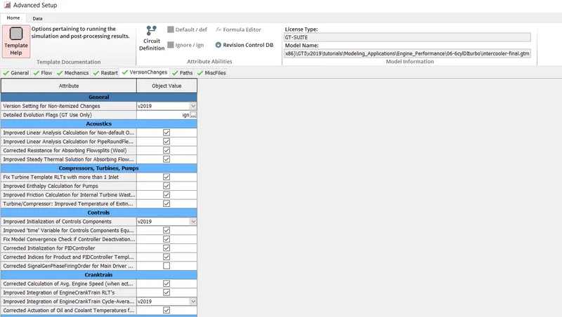
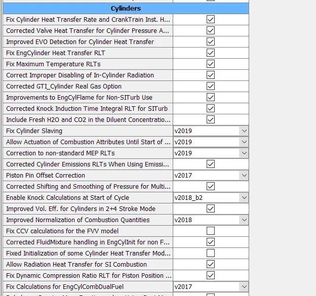
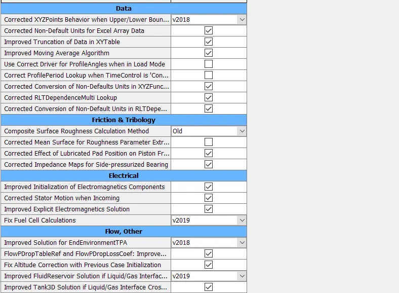
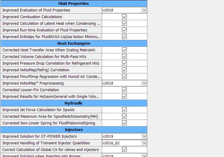
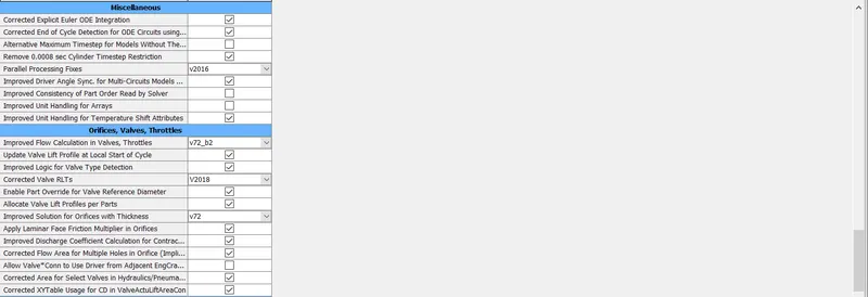
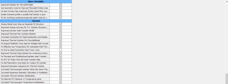
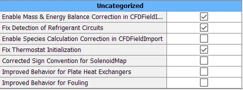
f) Paths- Default (ignored)
g) MiscFiles - File Type -ASCII
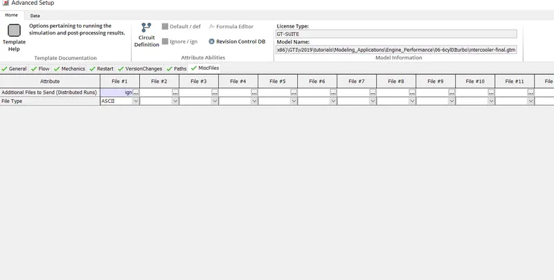
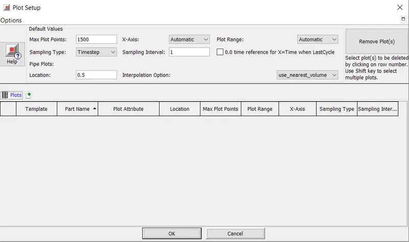
iii) Plot setup:- Values set as shown below
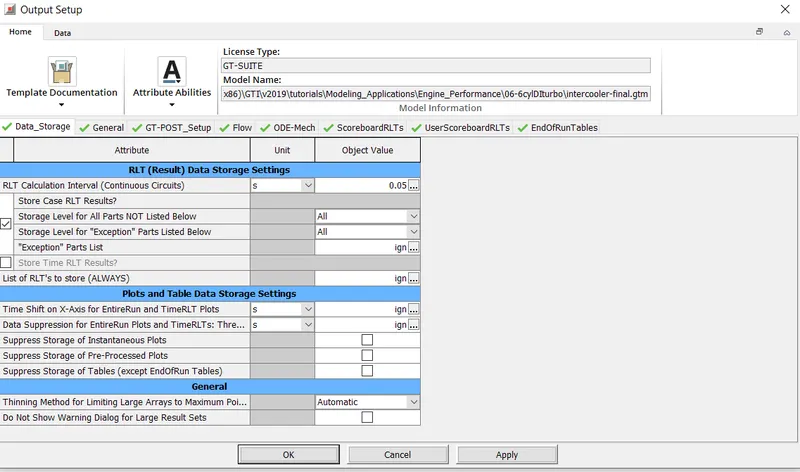
iv) Output Setup
a) Data Storage:- RLT Calculation Interval -0.05
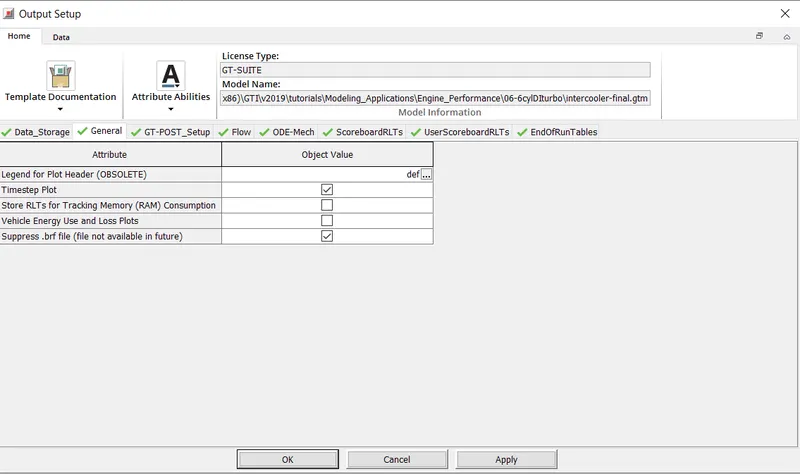
ii) General
a) Timestep Plot - Selected
b) Supress. brf file - Selected
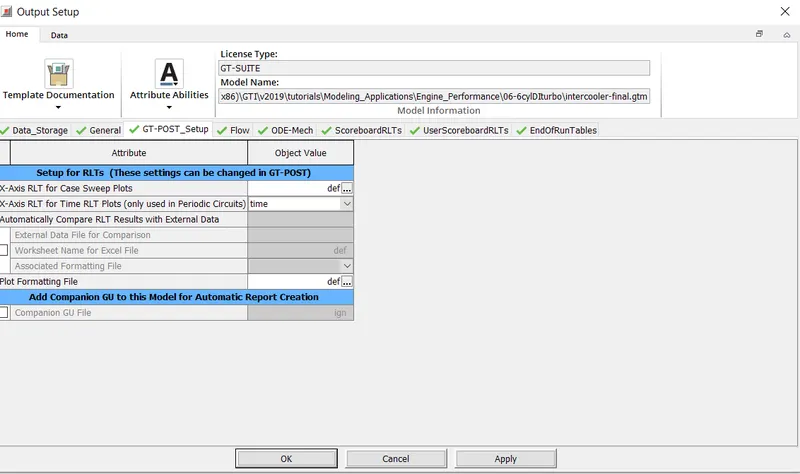
iii) GT Post
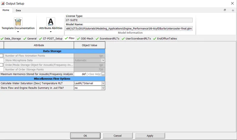
iv) Flow:- Calculate Water Saturation Temperature RLT - LastRLT interval
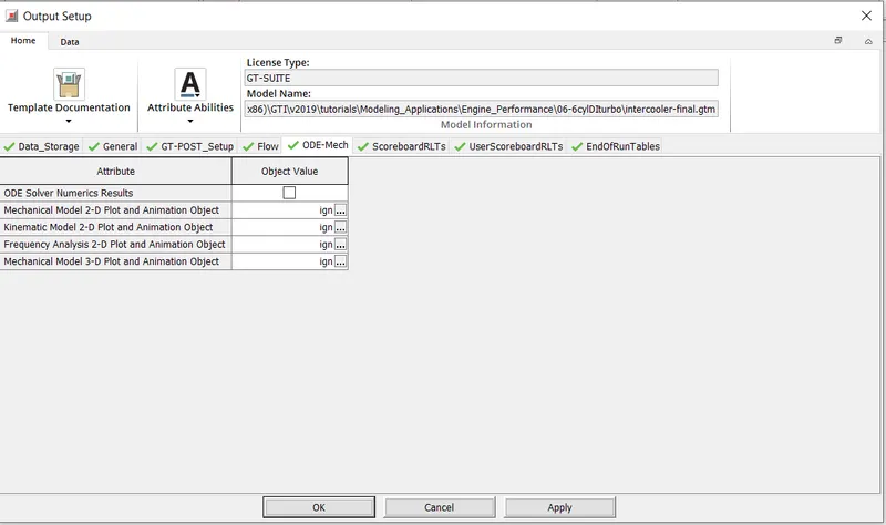
v) ODE MECH:- Parameters ignored
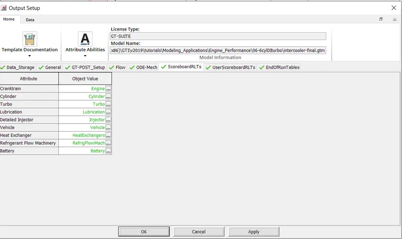
vi) ScoreboardRLTs:- Selections as shown below
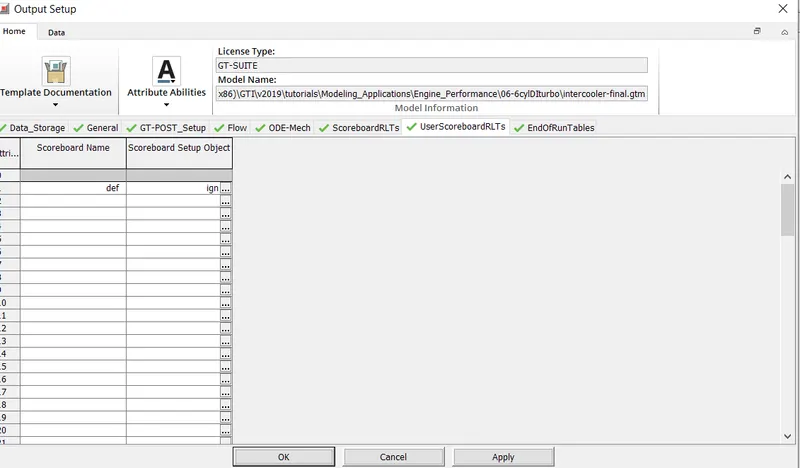
vii) User Scoreboard RLTs- Values as shown below
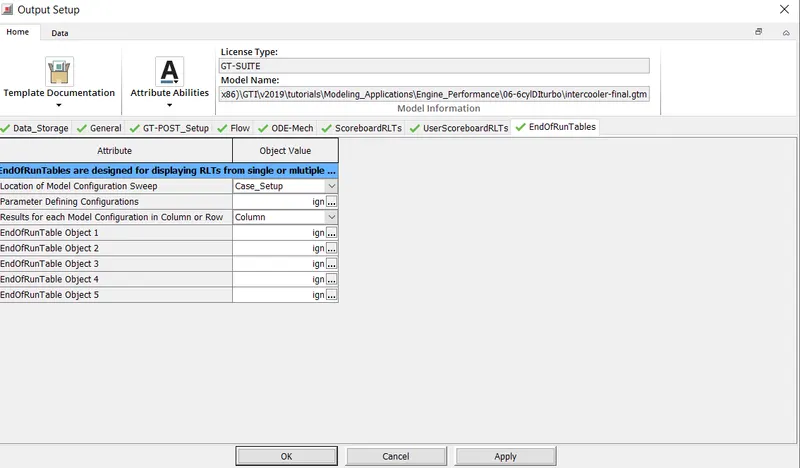
viii) End of Run Tables
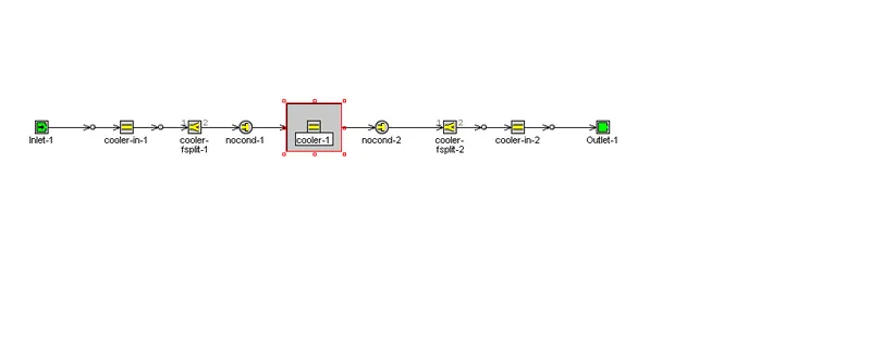
4) By double clicking on the cooler from the project map we get a console from where we can set the parameters as required.
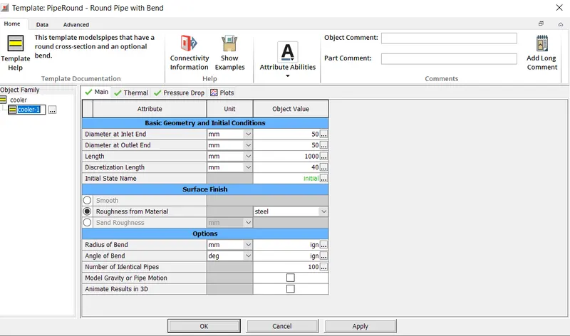
Diameter at the Inlet and Outlet end set to 50mm, Length set to 1000mm
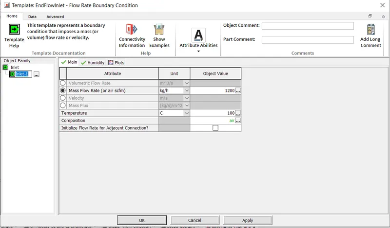
Inlet Mass FLow rate set to 1200 kg/d at a temeprature of 100 degree Celsius.
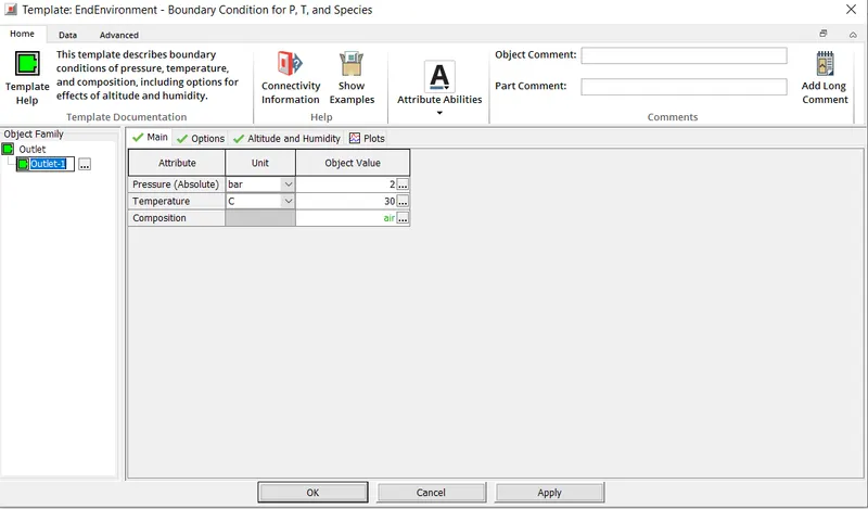
Outlet Temperature and pressure set to 30 degrees and 2 bar respectively.
Run Set up set to 1 second
Upon completion of the simulation, we can view the results by double clicking on the intercooler
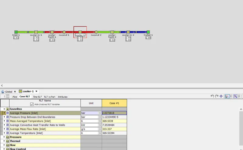
From the above window we can obtain the desired values as shown below.
Average Convective Heat Transfer Rate to Walls= 7.5539 kW
Pressure drop across the intercooler = 1.233449 * 10 ^E-5 bar