Week 1: Channel flow simulation using CONVERGE CFD
CHANNEL FLOW DESCRIPTION:
- A channel is a rectangular duct through which the flow takes place along the x-axis, by starting at the inlet and exiting at the outlet.
- We are assuming a 2D flow and neglecting the flow effects in the front and back side(since the similiarities are same along the z-axis while assuming a 2D flow).
- We need to ensure that the normal vector for our case should point towards the fluid i.e inside the duct.
- Species backflow happens if the outlet pressure is higher than the inner cell temperature causing the flow to reverse. If the flow reverses then it is going to come at 300K with air as the incoming fluid.
Boundary Setup:
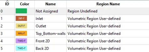
Geometry:
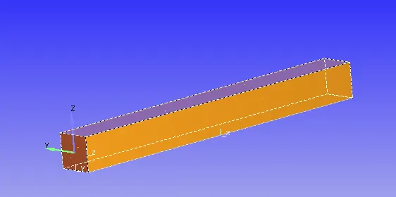
CASE 1:
For a base mesh size of 2e-4 we are evaluating the following properties:
MESH:
VELOCITY CONTOUR WITH VELOCITY PLOTS:
PRESSURE CONTOUR:
MASS FLOW RATE:
TOTAL PRESSURE:
CELL COUNT:
CASE 2:
For a base mesh size of 1.5e-4 we are evaluating the following properties:
MESH:
VELOCITY CONTOUR WITH VELOCITY PLOTS:
PRESSURE CONTOUR:
MASS FLOW RATE:
TOTAL PRESSURE:
CELL COUNT:
CASE 3:
For a base mesh size of 1e-4 we are evaluating the following properties:
MESH:
VELOCITY CONTOUR WITH VELOCITY PLOTS:
PRESSURE CONTOUR:
MASS FLOW RATE:
TOTAL PRESSURE:
CELL COUNT:
RESULTS AND DISCUSSION:
- The mesh ranges from a coarse to a finer grid size and we can see that total number of cells for each grid size increases accordingly. More the cells it will be better to capture the flow physics.
- The convergence is said to occur around the range 1800-3000 cycles.
- In the velocity plots we can confirm for the various mesh sizes we see the emergence of a parabolic profile due to the wall shear stress and the velocity increases as we move downstream towards the center along the y-axis.
- The flow is laminar because the pressure difference between the inlet and outlet is assumed to have a value of 1Pa, because of which no turbulence is said to occur.