Week 1: Channel flow simulation using CONVERGE CFD
Aim: The aim of the project is to simulate the flow of air through a channel. The following aspects would be investigated
- Impact of three different mesh sizes would be studied
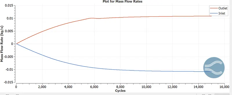
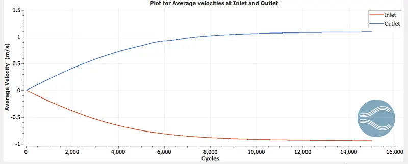
- Understand the development of flow with the aid of plots for velocity ,pressure and mass flow rate.
Theory:
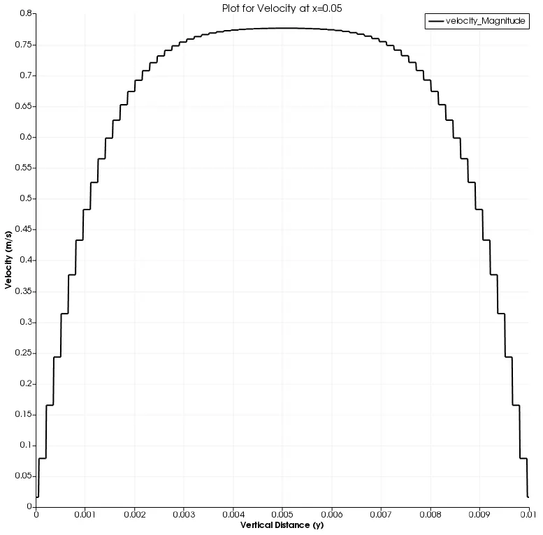
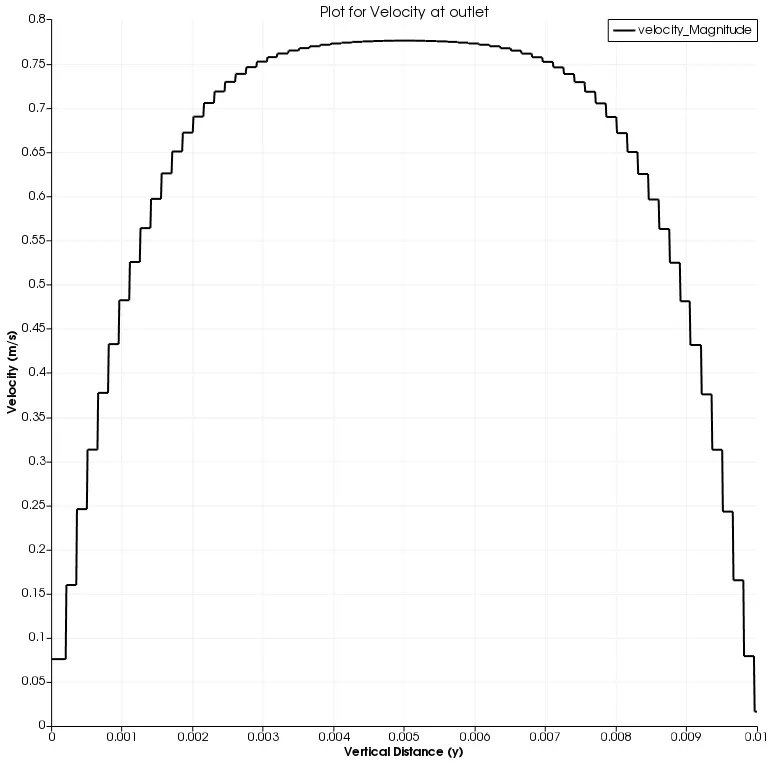
The flow through a rectangualr channel is characterized by 0 velocity at the wall due to no slip condition. Gradually as we move to the center of the channel in the vertical direction, the velocity magnitude increases and the maximum value is attained at the center. The resulting parabolic profile is shown below.
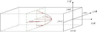
In our simulation we assume that the flow across the duct is two dimensional ,varying only in the x and y direction. Flow across any cross section is assumed to be constant and no variation is considered along z direction.
Case Setup:-
A. Geometry Creation
- Creating the Geometry:- A rectangular channel is created by selecting "Box" under "Create"
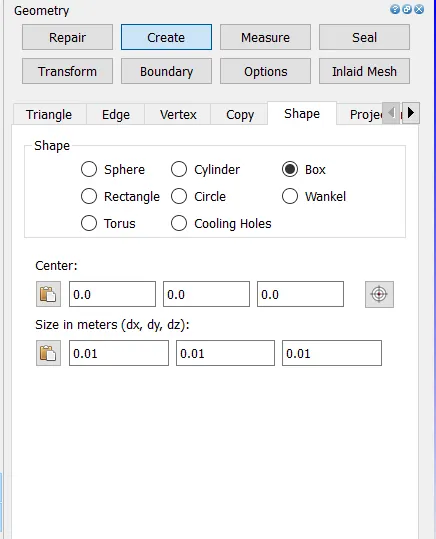
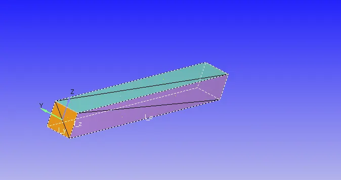
dx, dy and dz values are entered to create a channel as shown below
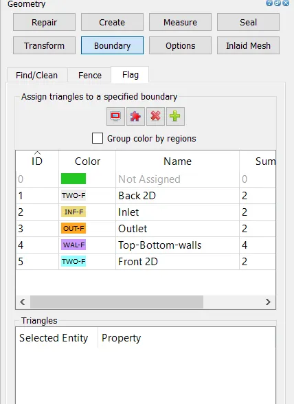
2. Creation of Boundaries: In the geometry which is created above, boundaries such as inflow, outflow , top and bottom walls, front and back faces are labelled.
3. Checking Orientation of Normals: Orientation of Normals were checked to ensure all the normals are pointing inwards. This was done using the Normal Toggle
4. Finally a Diagnosis check was run to ensure no errors in the geometry.
B Case Setup
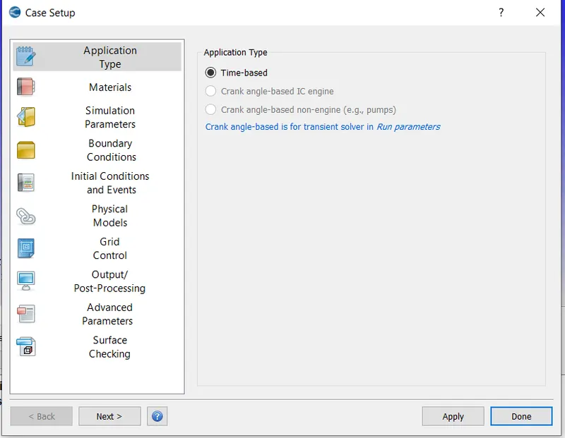
1. Application Type:- This was set to Time based
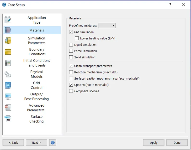
2.Materials:- This was set to Air
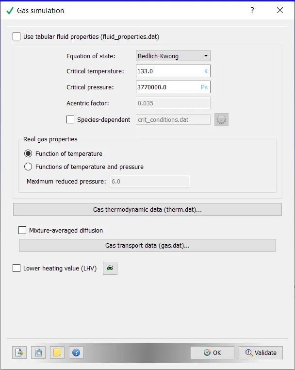
i) Gas Simulation: Default properties were retained
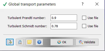
ii) Global Transposrt Parameters:- Default properties retained
3. Simulation Parameters
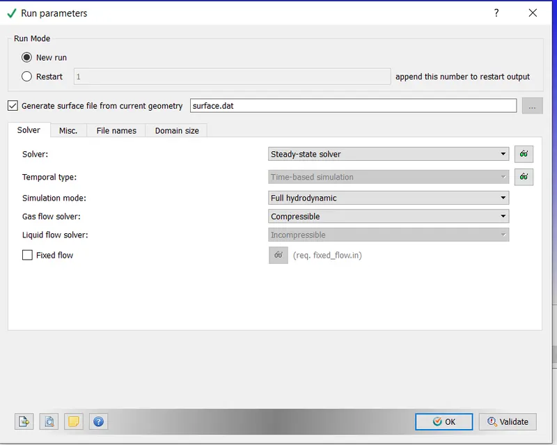
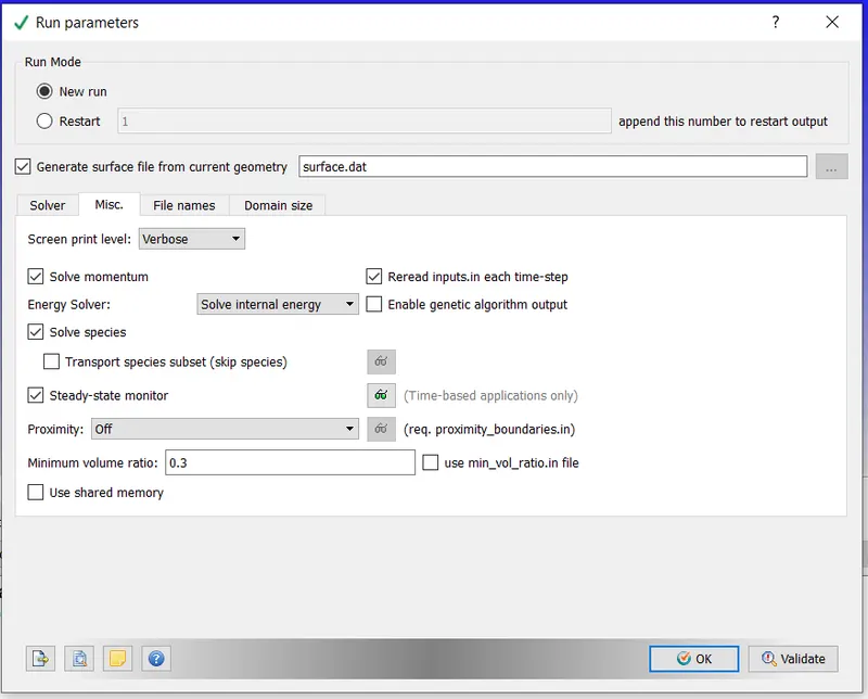
- Run Parameters:- Steady state solver was used. Simulation mode was set to Full Hydrodynamic. Gas Flow solver set to Compressible
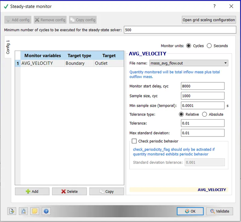
- Steady State Monitor:- Minimum no of cycles for to be executed for Steady state solver -500
Monitor Start Delay, cyc :- 8000
Sample size cyc :- 1000
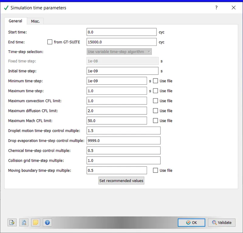
- Simulation Time Parameters:- The parameters were set as displayed below. Max CFL limit set to 1.0
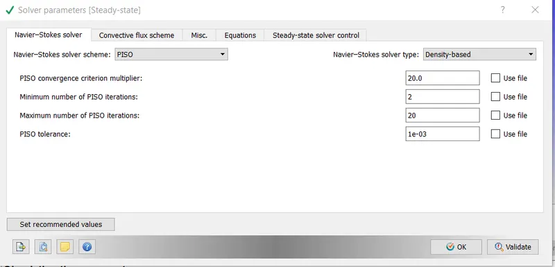
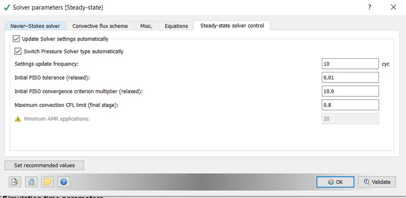
- Solver Parameters:- A denisty based PISO solver was used, Maximum Convection CFL limit set to 0.8.
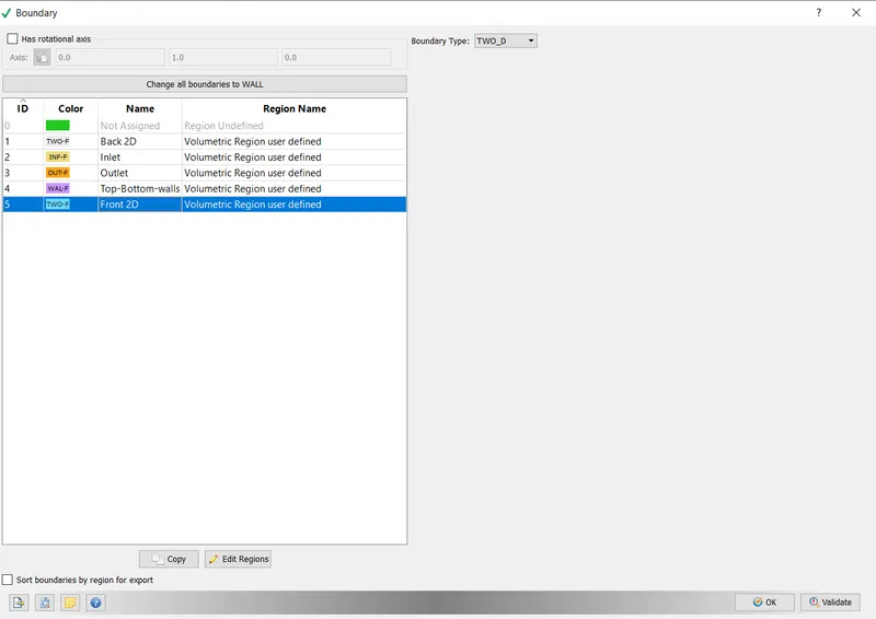
4. Boundary
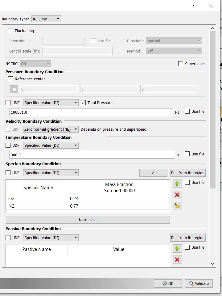
- Inlet:- Boundary flow - Inflow
Inlet Pressure- 100001 Pa
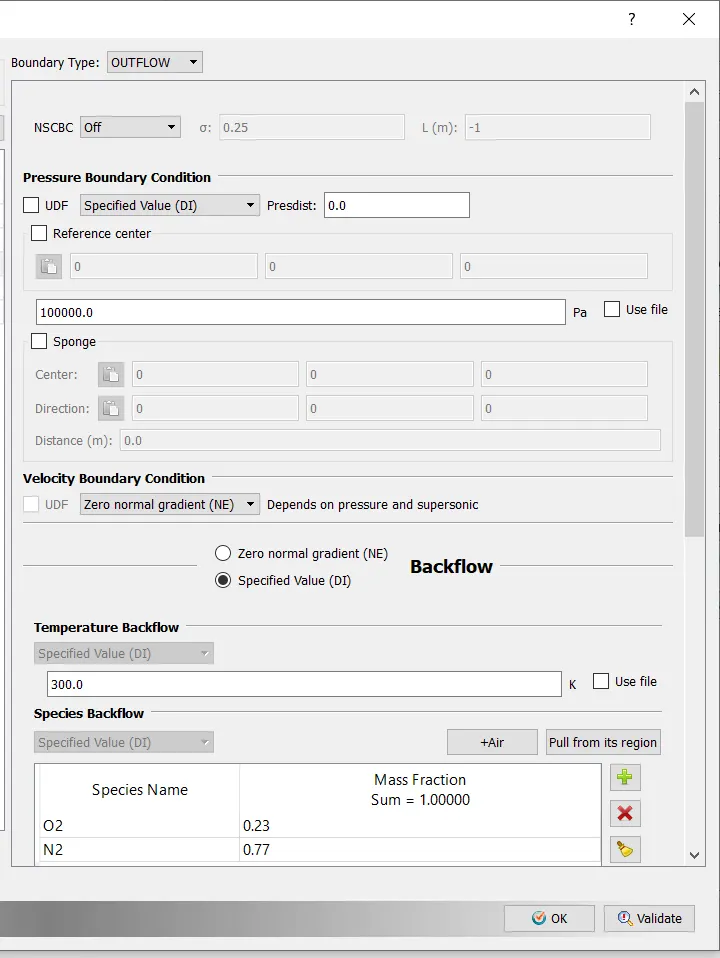
- Outlet- Boundary - Outflow
- Top and Bottom Walls:- Stationary wall with Fixed surface movement used

- Front and Back faces set to Two D
4. Initial condition and events
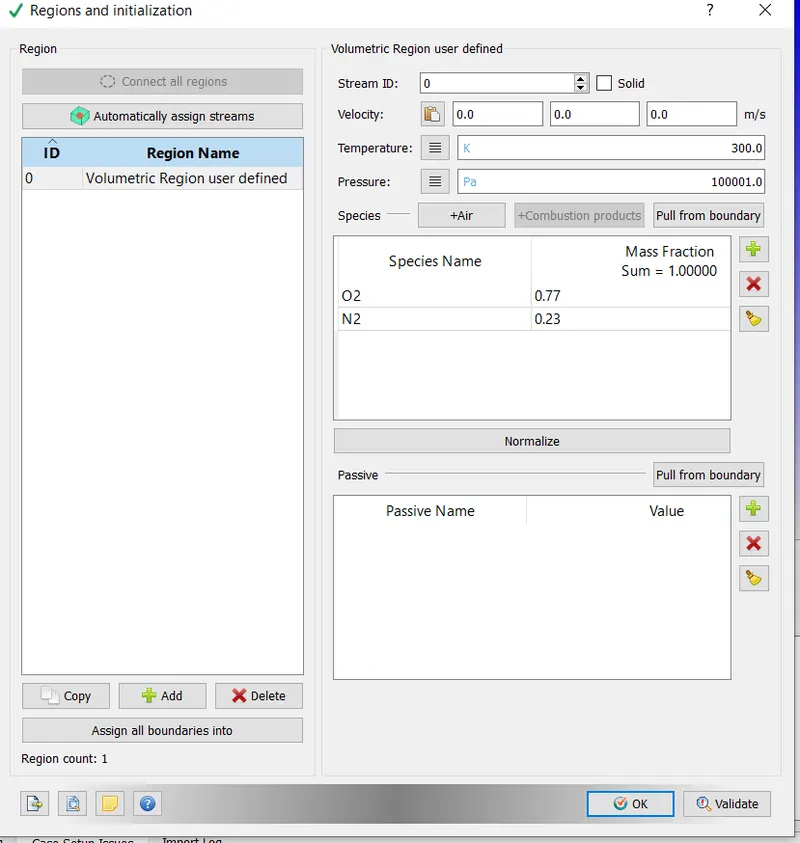
The created geometry was selected as the Volumetric Region
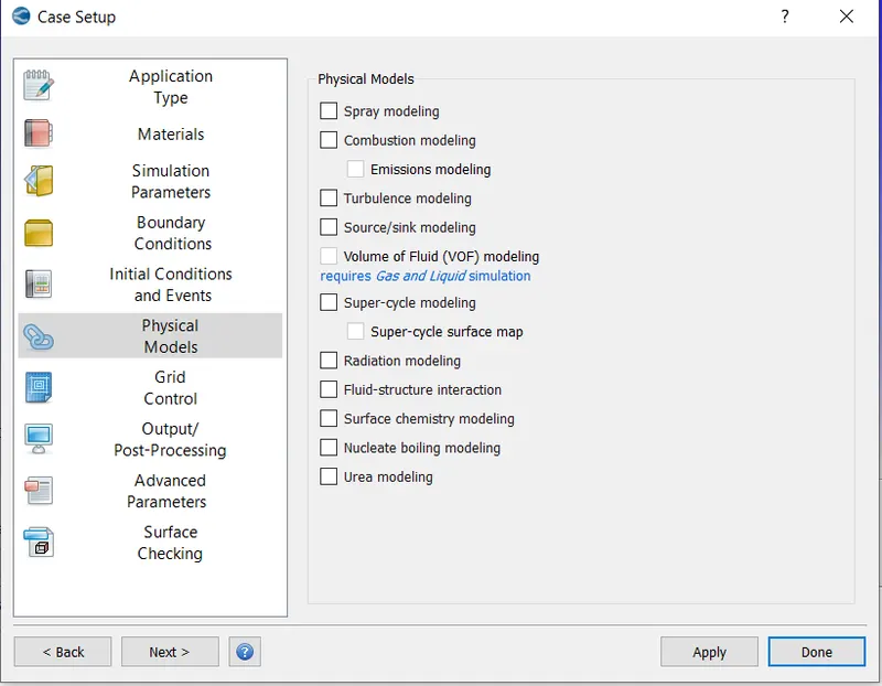
5. Physical Models:- Default retained
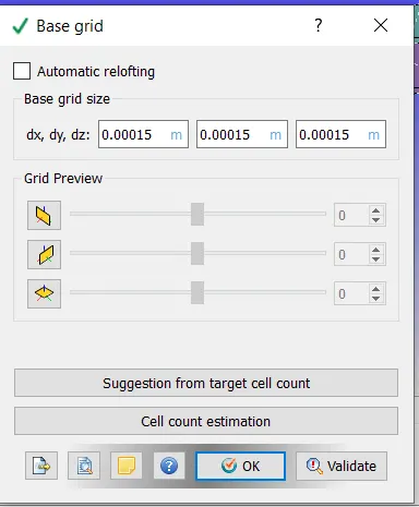
6. Grid Control:- Base Grid. Here the size of the mesh for the three cases is entered
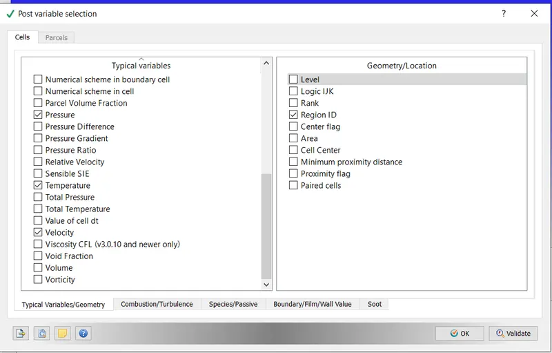
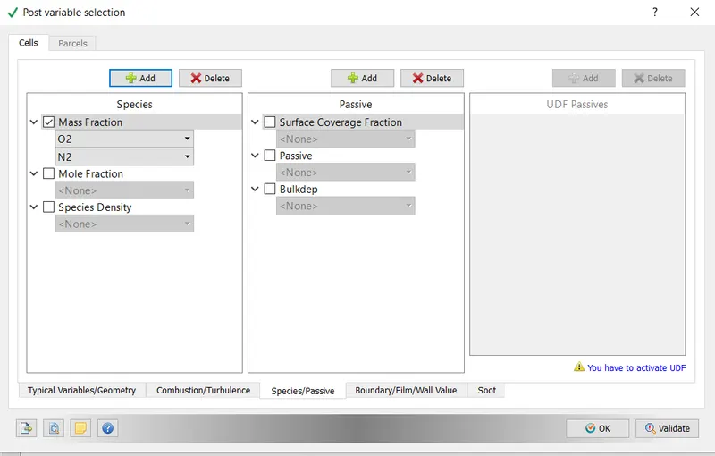
7. Output/Post Processing:- The variables that we intend to see during post processing are selected. In this case Density, Pressure , Temperature and Velocity were selected.
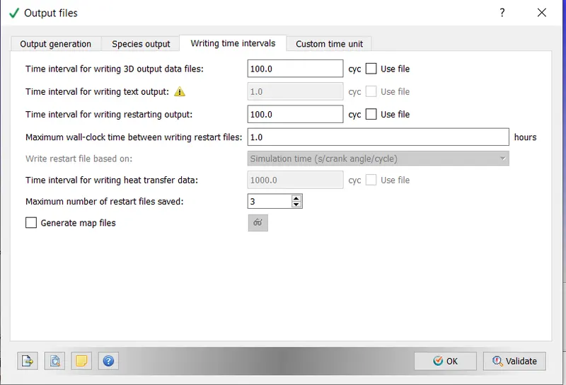
Also the frequency of generation of output files were set below
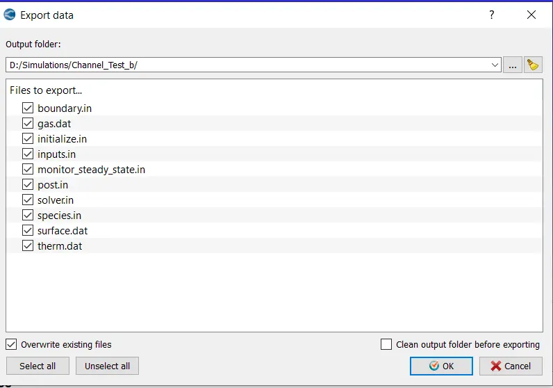
After setting the above, the input files were exported to a directory
In order to execute the simulation, the directory in which these input files were stored was accessed in Cygwin and the following command was typed "mpiexec.exe -n 4 converge.exe"
After the Simulation was executed, the results were converted into a form which would be compatible with Paraview. This was done using the post_convert.exe command.
Results after Post Processing
1) Case 1 ( dx=dy-dz=2e-4)
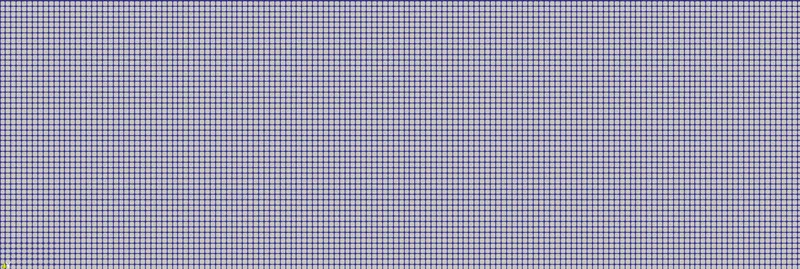
- View of the Mesh

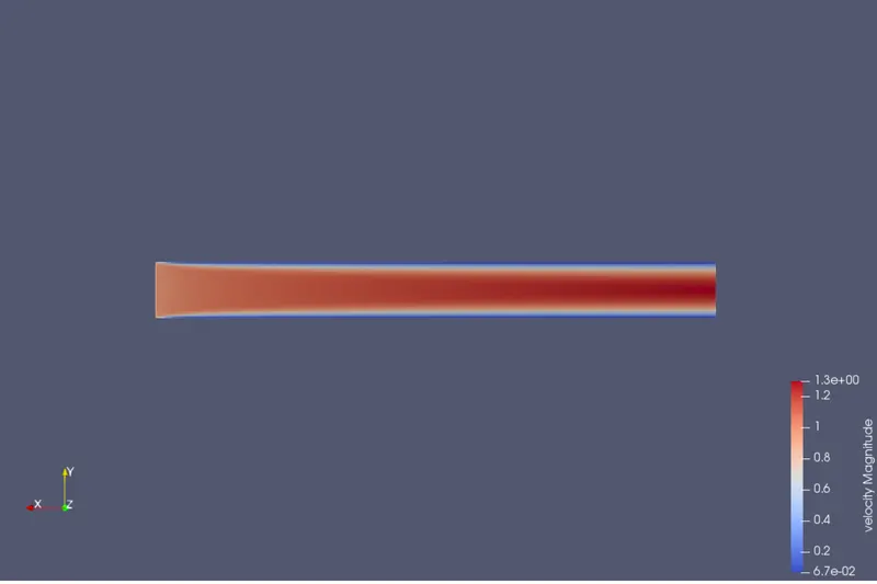
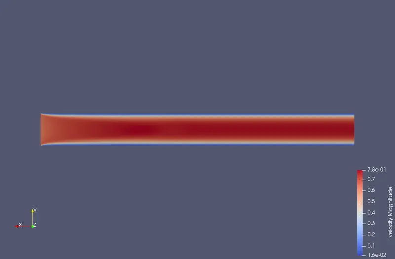
- Velocity Contour
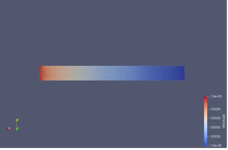
- Pressure Contour
Plots for
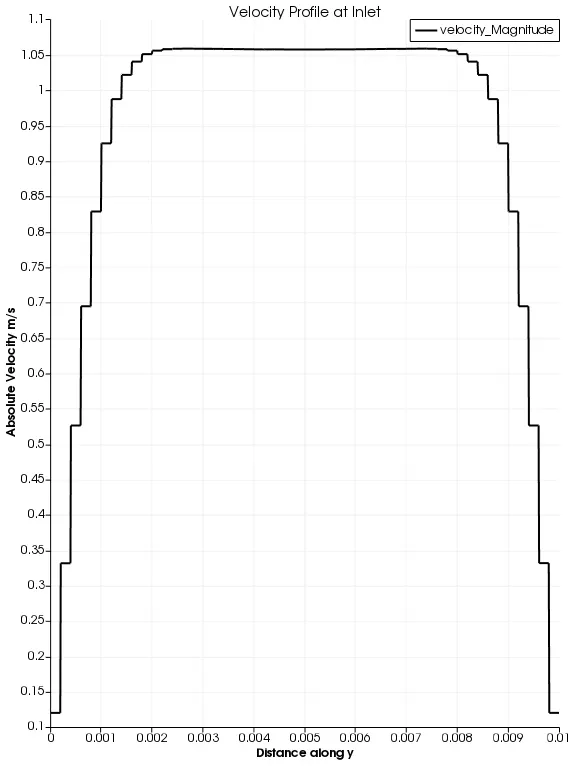
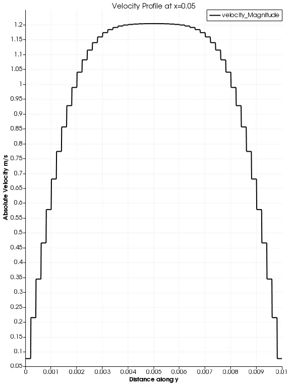
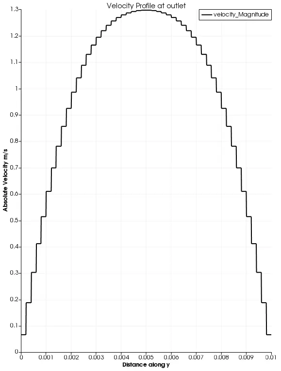
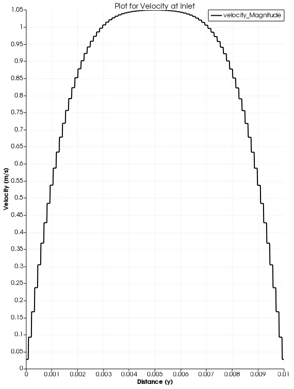
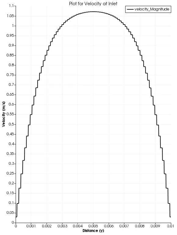
- Velocity (After approximately 15000 cycles)
i) Inlet
ii) at X=0.05m
iii) At Outlet
- Mass Flow Rate
- Average Velocity
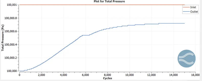
- Total Pressure
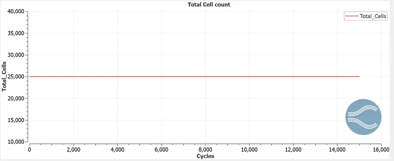
- Cell Count
Velocity Animation
https://www.youtube.com/watch?v=sIEfBayXXIY&ab_channel=VivekRamesh
2. Case 2 (dx=dy=dz= 1.5 e-4)
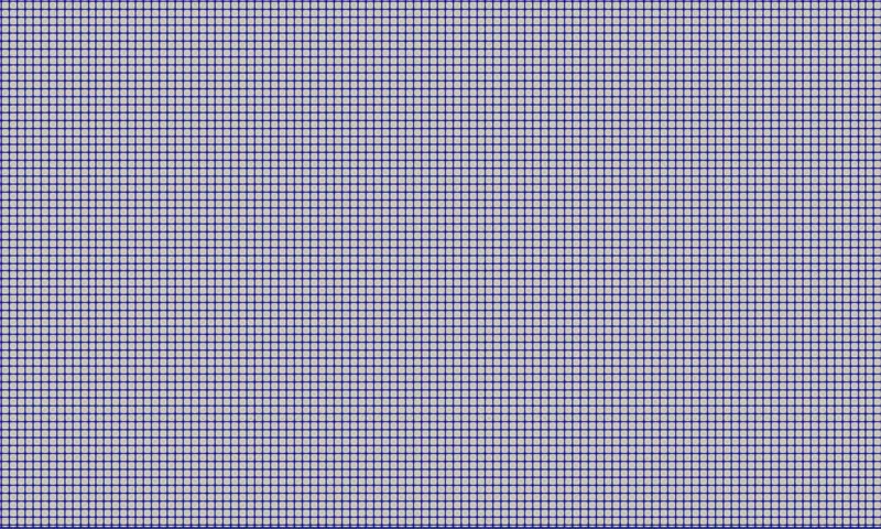
- View of the Mesh

- Velocity Contour
- Pressure Contour
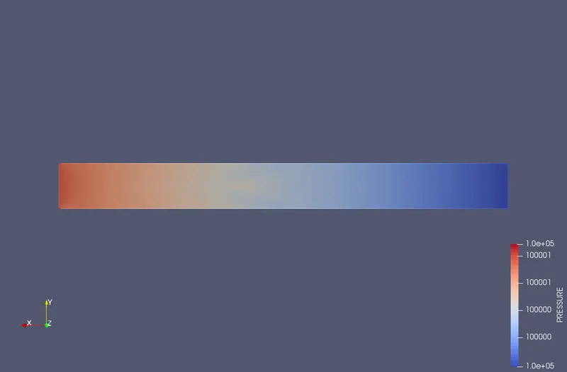
Velocity
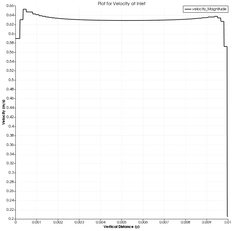
- Velocity at Inlet
- Velocity at x=0.05m
-Velocity at outlet
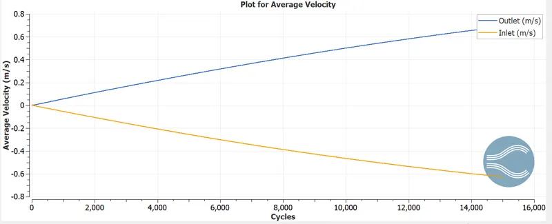
- Plot of Average Velocity
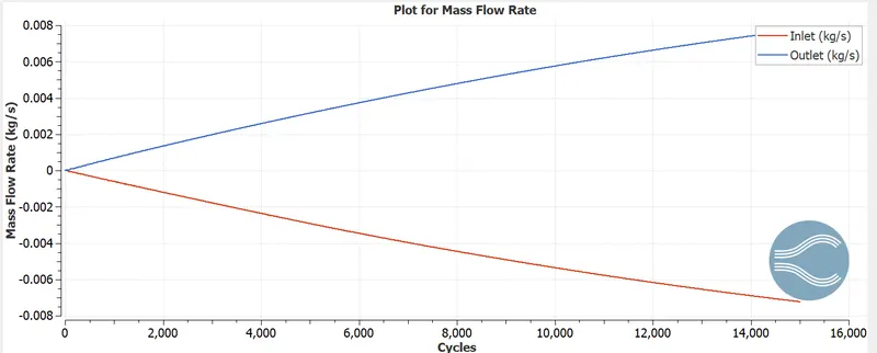
- Plot for Mass Flow Rate
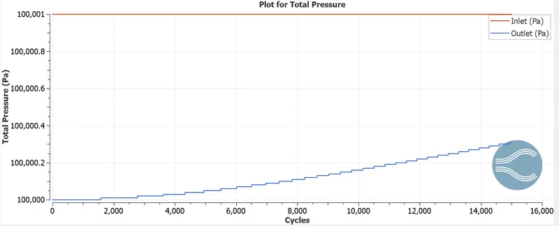
-Plot for Total Pressure
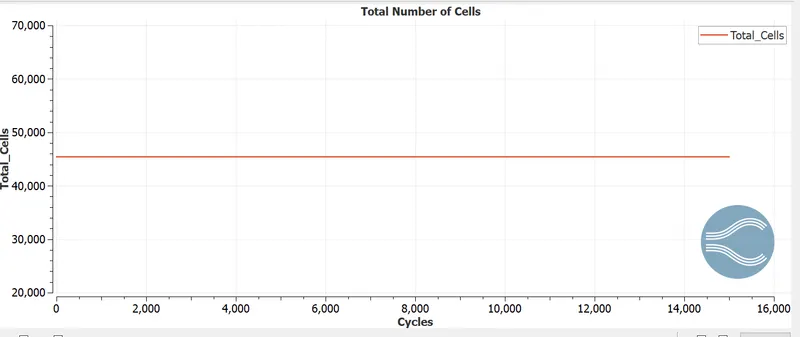
Plot for Total number of cells
Velocity Animation
https://www.youtube.com/watch?v=yJa-r3vlj-U&ab_channel=VivekRamesh
Case 3 (dx=dy=dz=1.2 e-4)

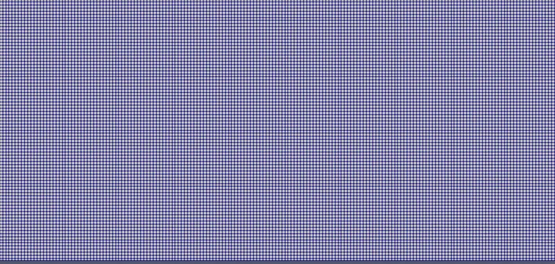
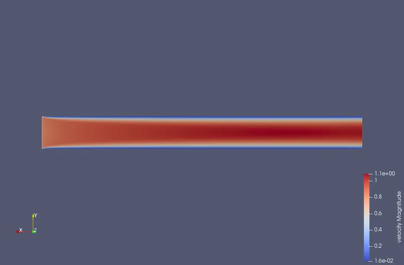
- Velocity Contour
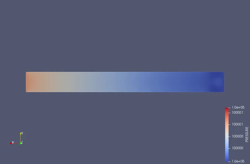
- Pressure Contour
- Velocity
i) Inlet
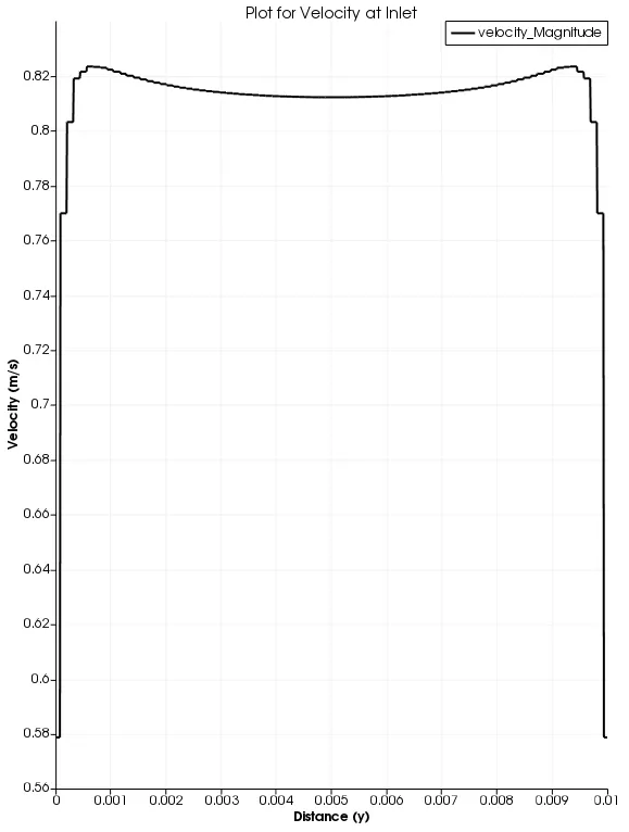
ii) x=0.05
iii) At outlet
- Plot for Average Velocity
- Plot for Mass Flow Rate
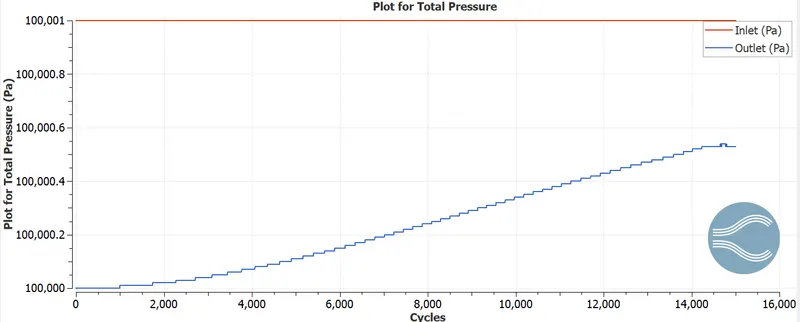
- Plot for Total Pressure
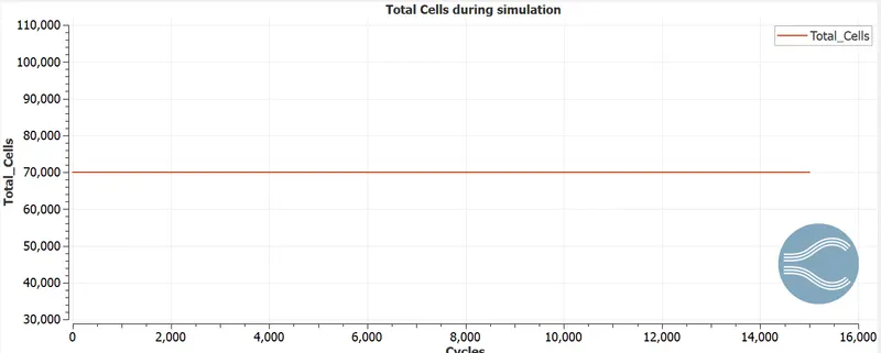
-Cell Count
Velocity Animation
https://www.youtube.com/watch?v=ywe_wL19XHk&ab_channel=VivekRamesh
Observations
1) Pressure difference between inlet and outlet is what causes the flow in the channel
2) From the contour plots of velocity and velocity profile at different distances, we observe that in the entrance region the profile is flat. As we move across the channel from inlet to outlet the profile develops into its characteristic parabolic shape and this is maintained till the outlet.
3) From the velocity contours we also observe that in the regions adjacent to the wall the fluid velocity is zero. This is due to the no slip condition. As we move across the channel the thickness of the fluid region which is at rest also increases.
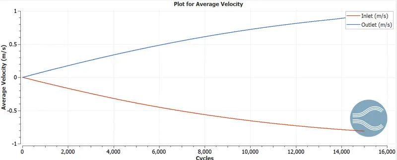
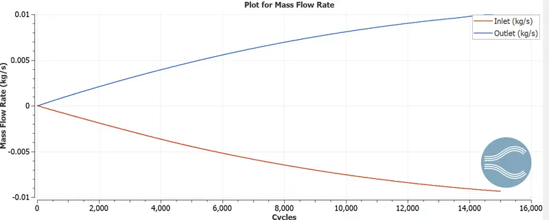
4) We find that the profile of the mass flow rates and average velocity at the inlet and outlet to be similar. However the plots are inverse of each other, in accordance with laws of conservation of mass.
5) From the plot of Total pressure we find that while the pressure at intlet remains constant, the pressure at outlet marginally increases with during the computational cycle
6) The cell count for the three cases remained a constant during the simulation indicating that cells were intact during the computational simulation
7) With the refinement of mesh the observe that computational time significantly increases.
8) From the animation we can understand how the velocity profile develops. intially it is zero everywhere in the flow field and with passage of time we can observe how two distinct regions in the channel emerges, namely the no slip region and the irrotational flow region