Challenge
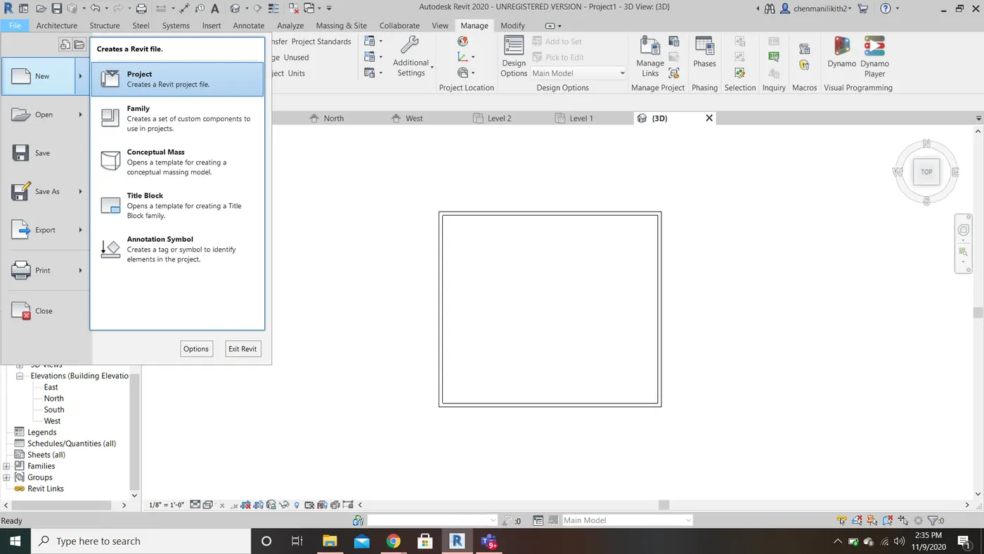
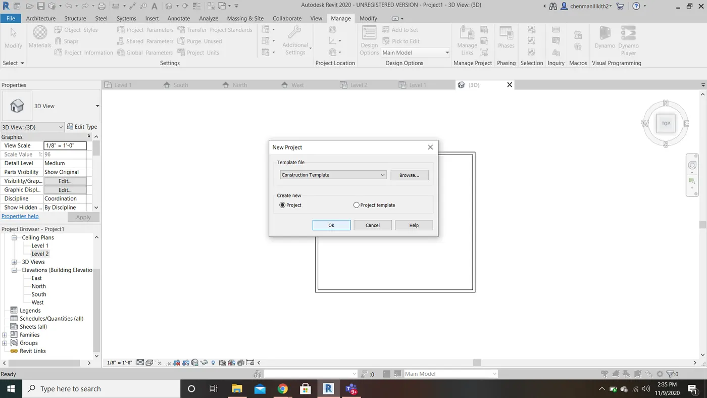
1) From the file menu, create a new project (Structural / Architectural / Construction template ) and name the project appropriately.
AIM: To save the new project file, close and open using icons from file toolbar
TOOLS USED: File Tool, New project Tool
PROCEDURE:
- Click the file at the top left corner.
- Select the New option.
- Click on the project, a new project dialog box appears.
- Click ok.
2) Save the new project file. Close and open using icons from file toolbar
AIM: To save the new project file, close and open using icons from file toolbar
TOOLS USED: File Tool, Save As Tool
PROCEDURE:
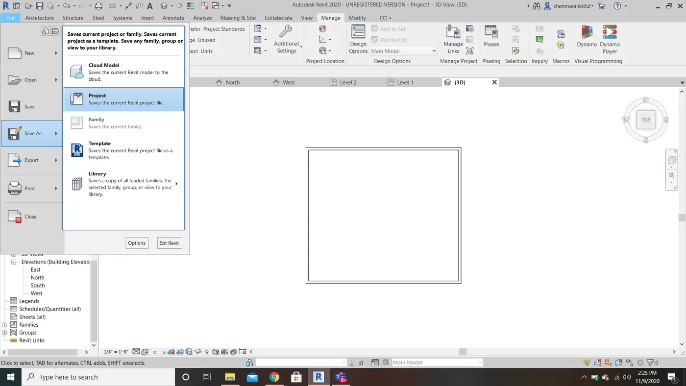
- Click the file at the top left corner.
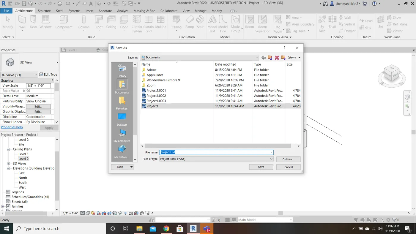
- Select the Save As option.
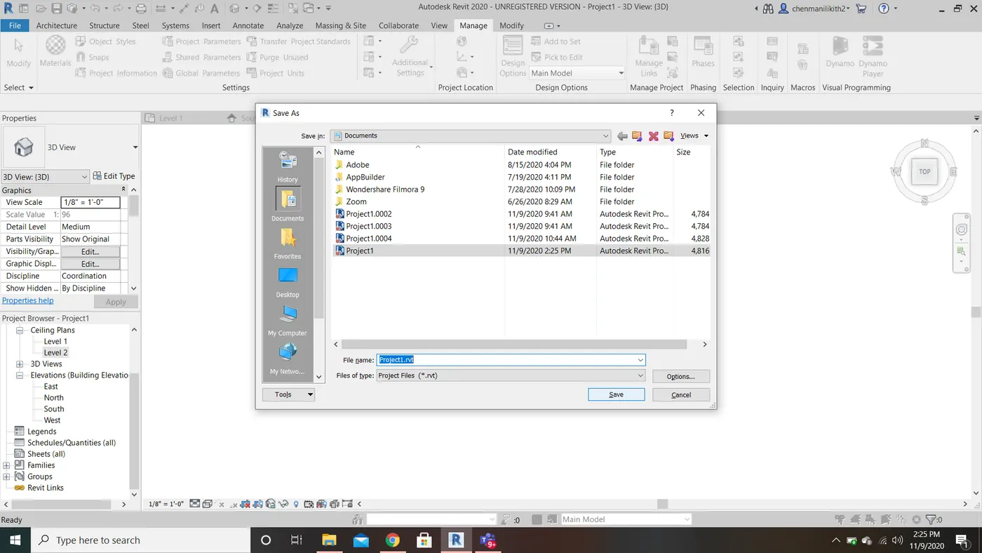
- Click on the project, a save as dialog box appears.
- Enter the file name.
- Select the file location to be saved.
- Click save.
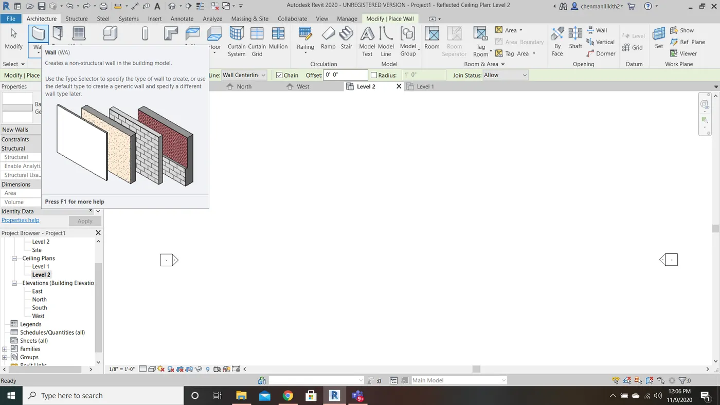
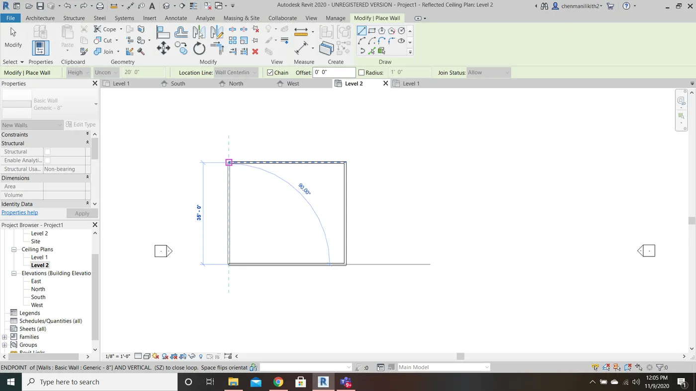
3) From the architecture/ structure tool bar familiarize with options to draw a wall. Create a rectangular layout of walls of about 40’-0” X 35’-0”
AIM: To create a rectangular layout of walls of about 40’-0” X 35’-0”.
TOOLS USED: Wall Tool, Architecture Tool
PROCEDURE:
- Click architecture tool bar, select the wall tool.
- Draw a wall of your requried dimensions (40’-0” X 35’-0”).
4) From Annotate tool bar use aligned option to add dimensions to the layout.
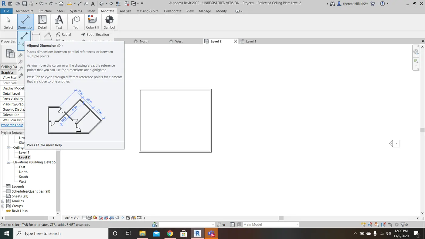
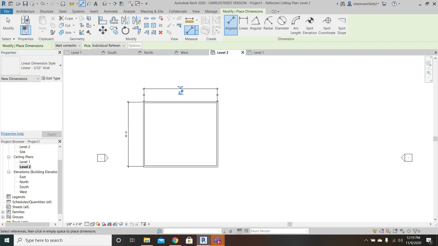
AIM: To add dimensions to the layout.
TOOLS USED: Annotate tool bar, Aligned tool
PROCEDURE:
- Click Annotate tool bar, select the aligned tool.
- Using aligned tool select the opposite sides of the rectagle, you will get your dimensions.
5) Use the properties browser to switch to different wall types.
AIM: To use the properties browser to switch to different wall types.
TOOLS USED: Properities Tool, Edit Type Tool
PROCEDURE:
- Draw a wall of your requried dimentions.
- Select any side of the wall, automatically you will be directed to the modify wall tool.
- Click edit type, a dialog box will be appeared.
- Select the desired wall type in the type tool box.
- Click ok.
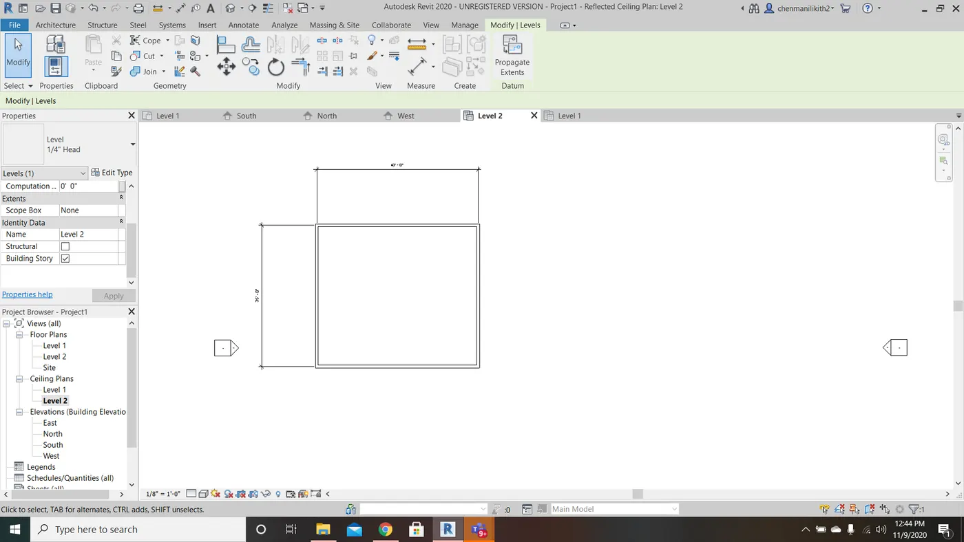
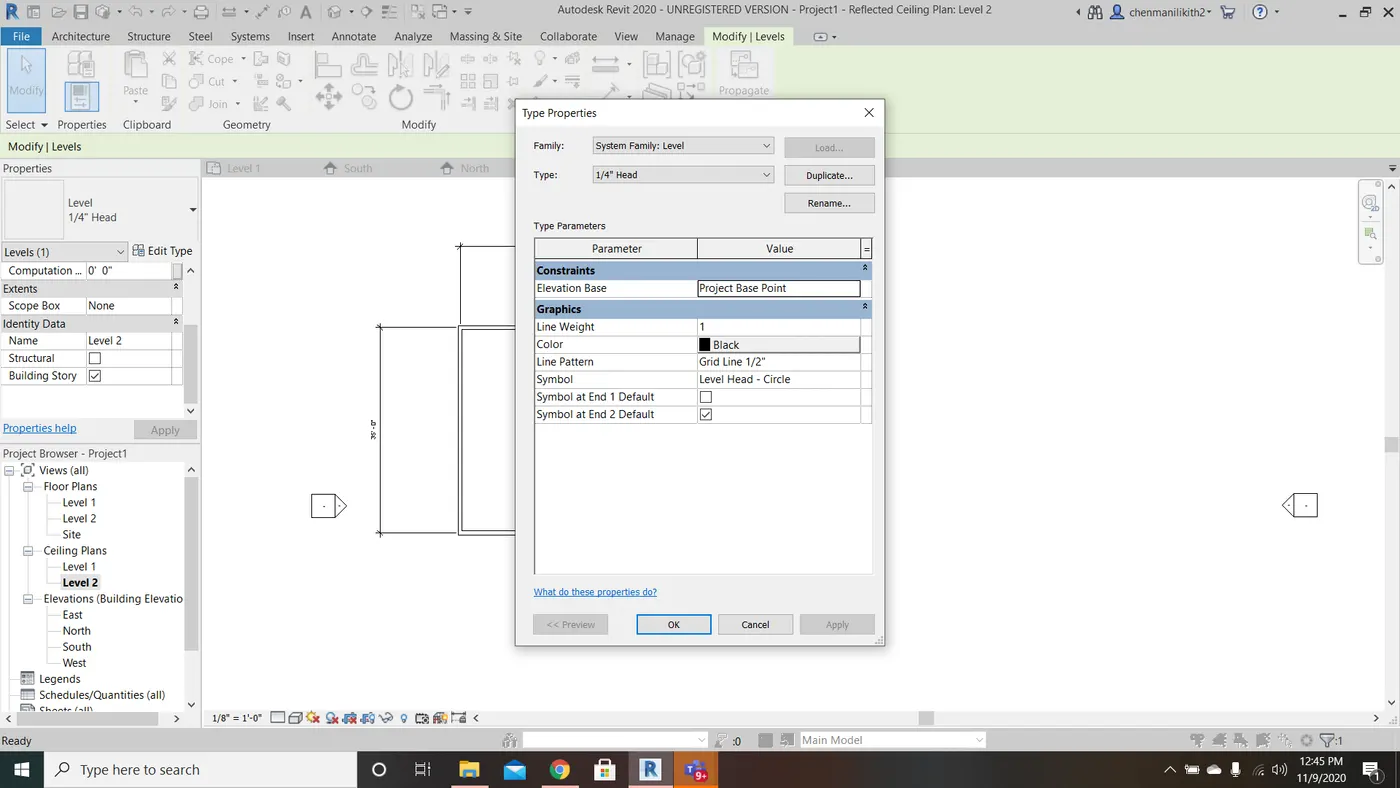
6) Create a 3D view from the view tool bar and save the view with appropriate name.
AIM: To Create a 3D view from the view tool bar and save the view with appropriate name.
TOOLS USED: Wall tool, Default 3D view tool
PROCEDURE:
- Click architecture tool bar, select the wall tool.
- Draw a wall of your requried dimensions.
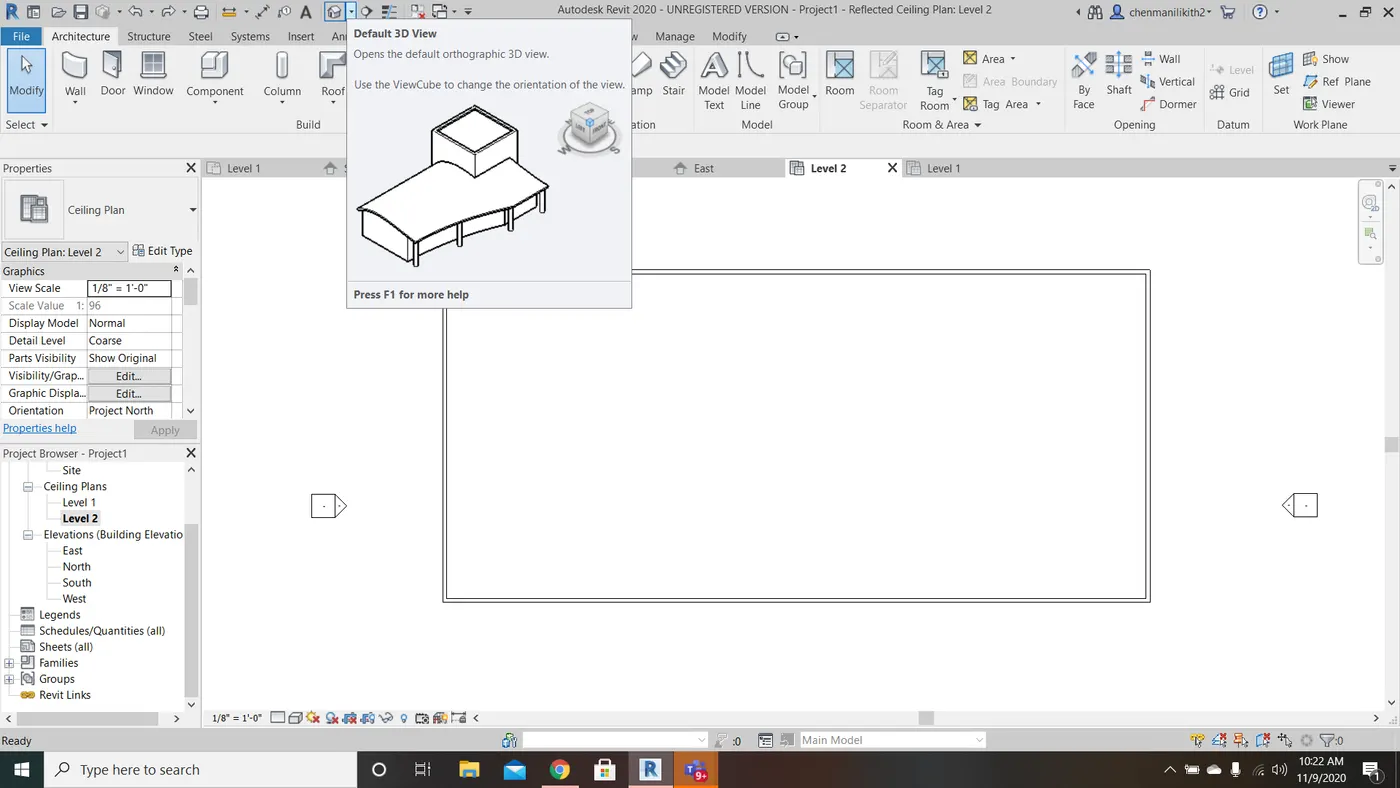
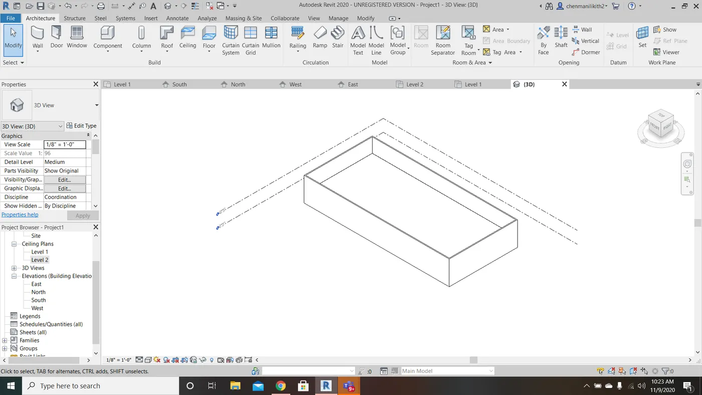
- Click the 3D view tool (the 2D view changes to 3D view).
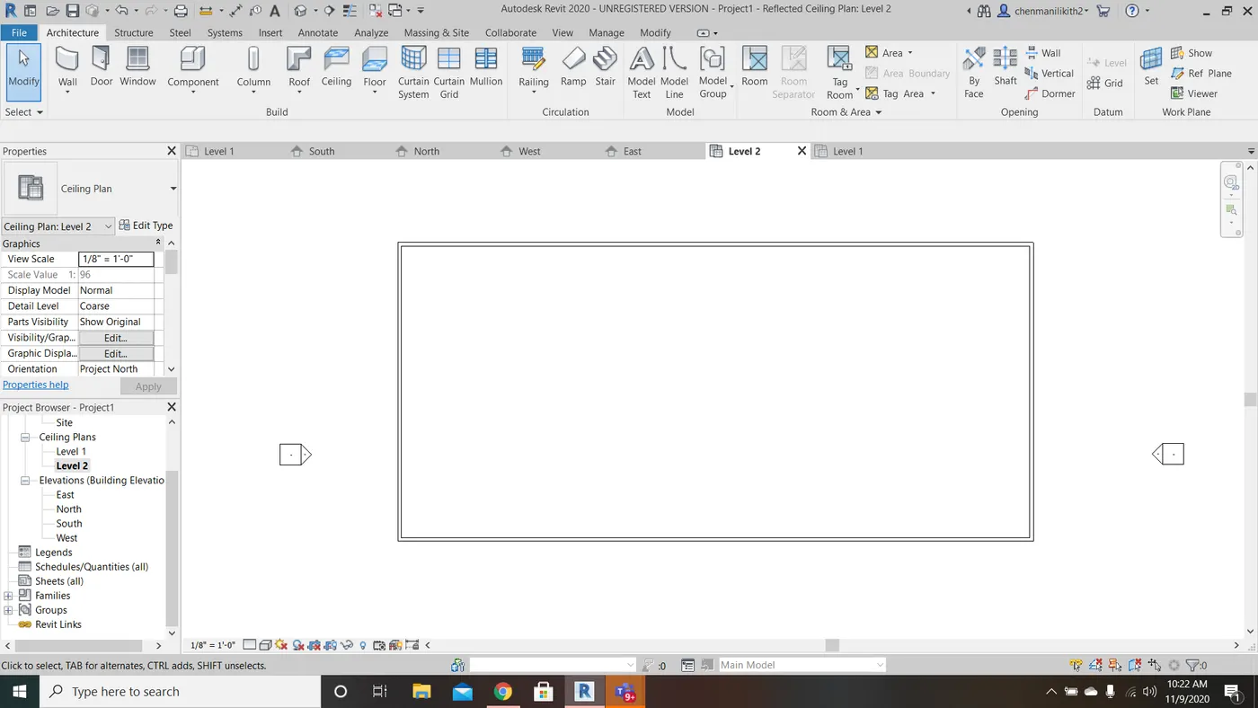
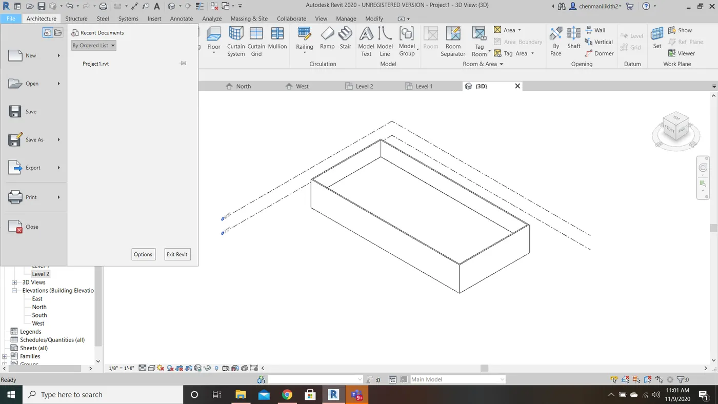
- Now to save your project file, select file option.
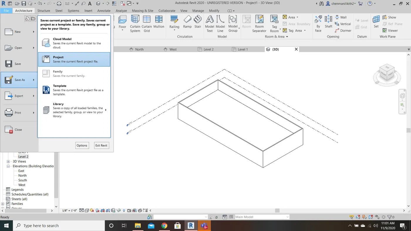
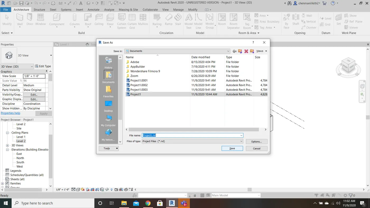
- Click save as option.
- Select the project option.
- A save as dialog box will be appear.
- Select the location of your file.
- Now click on save option.
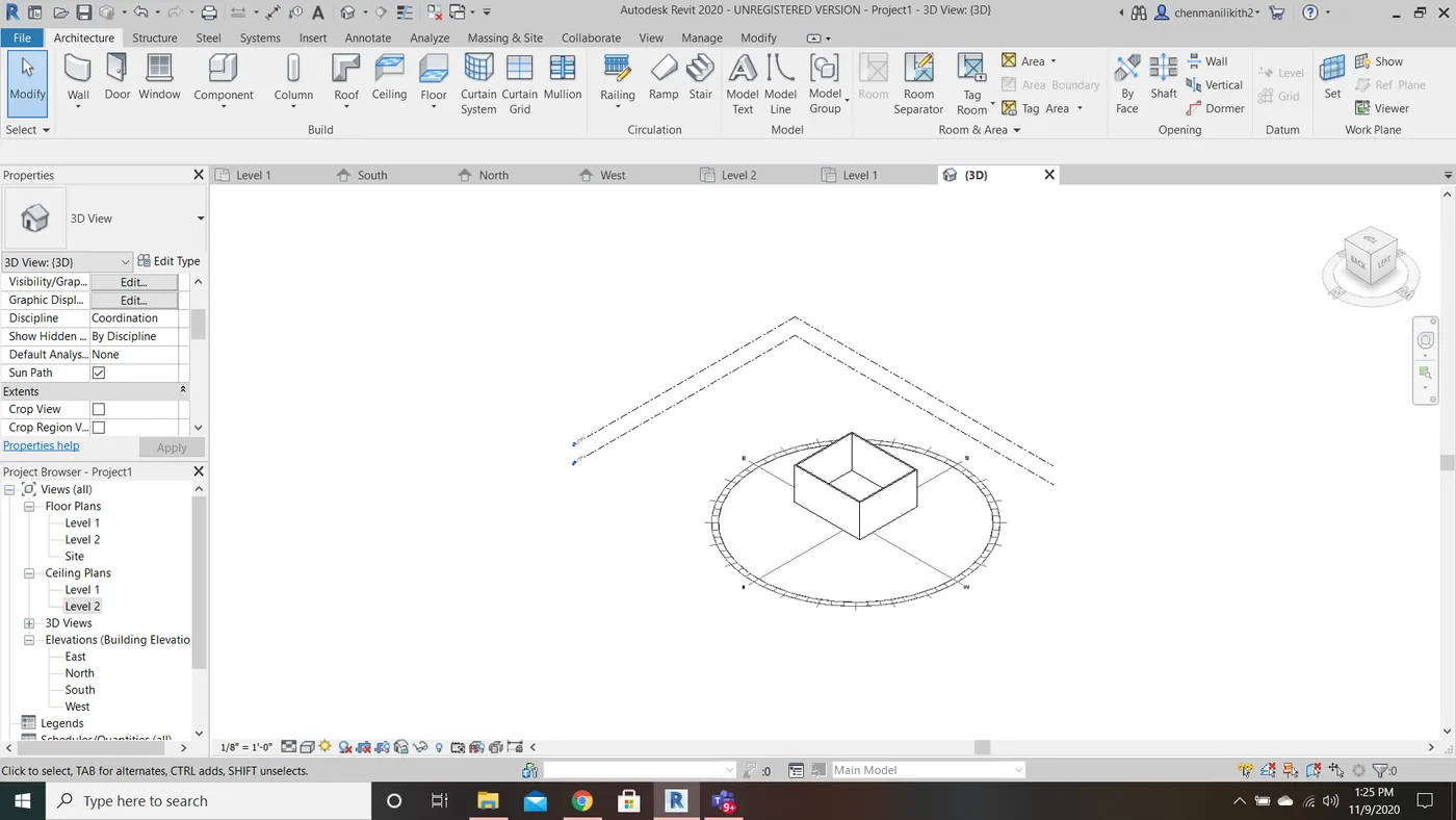
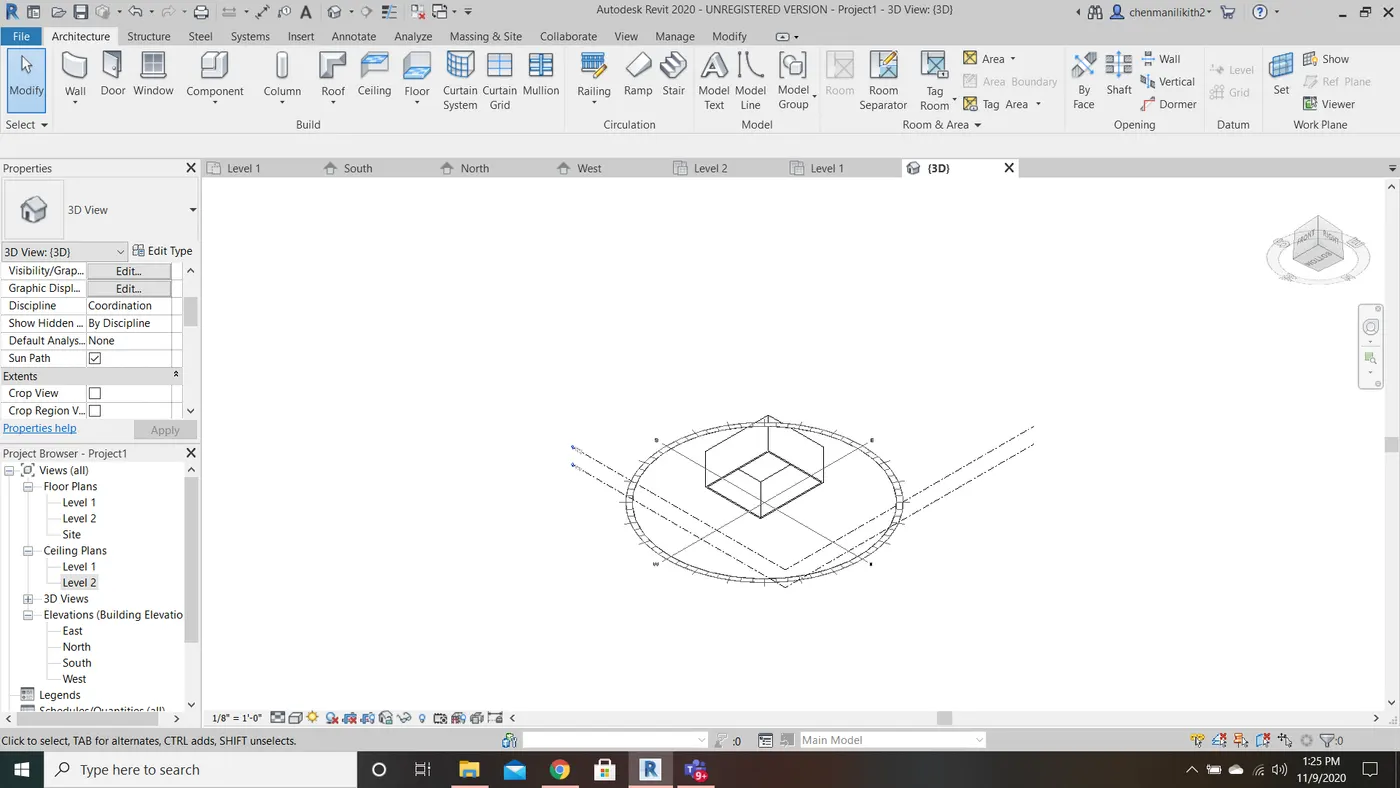
7) Navigate through the 3D model using view cube. Orbit/pan through the model layout created.
AIM: To navigate 3D model using view cube and Orbit/pan through the model layout created.
TOOLS USED: View Cube
PROCEDURE:
- Draw a wall of your requried dimentions.
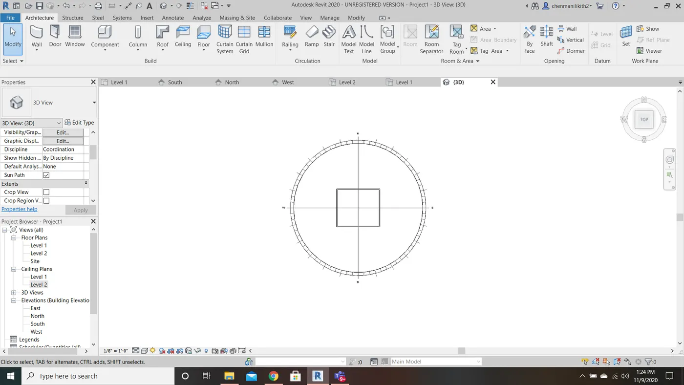
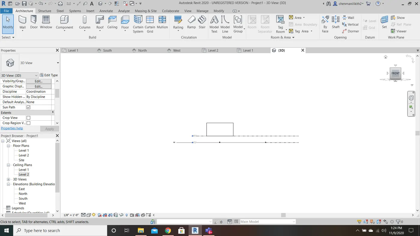
- Click on the cube which is visible at top right and rotate the pan according to your requried view.
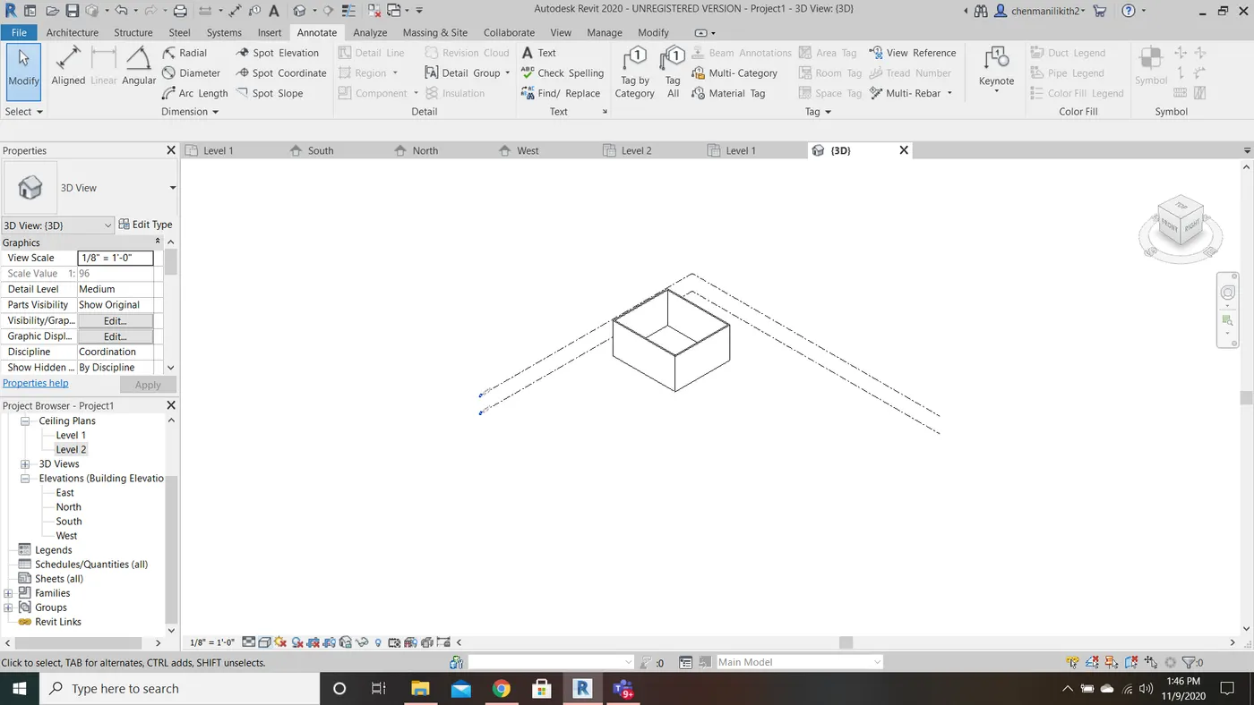
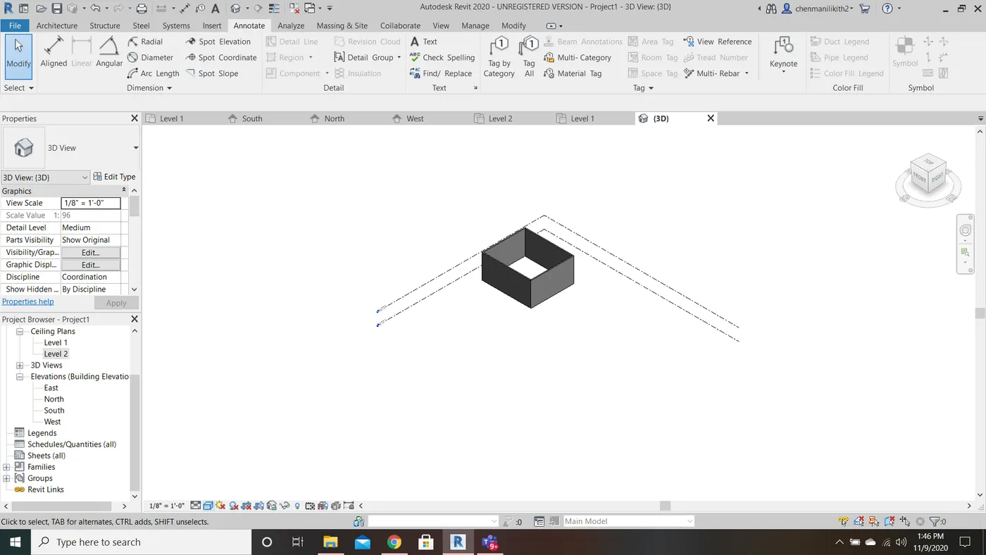
8) Use the visibility settings option below to switch model to shaded, realistic, hidden lines options.
AIM: To switch model to shaded, realistic, hidden lines options.
TOOLS USED: Visual Style Tool
PROCEDURE:
- Draw a wall of your requried dimentions.
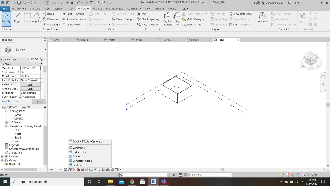
- Select the visual style tool which will be appeared at bottom left .
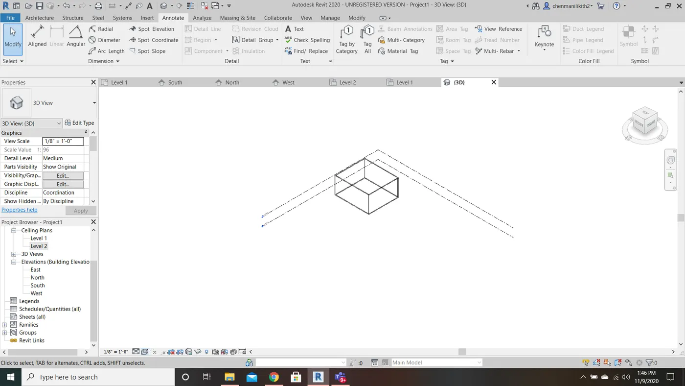
- A dialog box appears consisting of wireframe, hidden lines, shaded, consistent colours, realistic.
- Now we requrie to switch model using shaded, realistic, hidden lines options.
9) Turn the sunlight on and off to view shadings in the layout created.
AIM: To turn the sunlight on and off to view shadings in the layout created.
TOOLS USED: Sun Settings Tool
PROCEDURE:
- Select the sun settings tool which is located at the left bottom.
- There we can find two options one is sun path ON and other is sun path OFF.
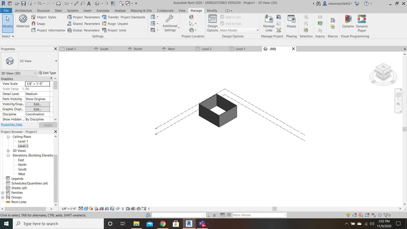
- In the below Fig.1 and Fig.2 we can find the sun path ON and OFF.
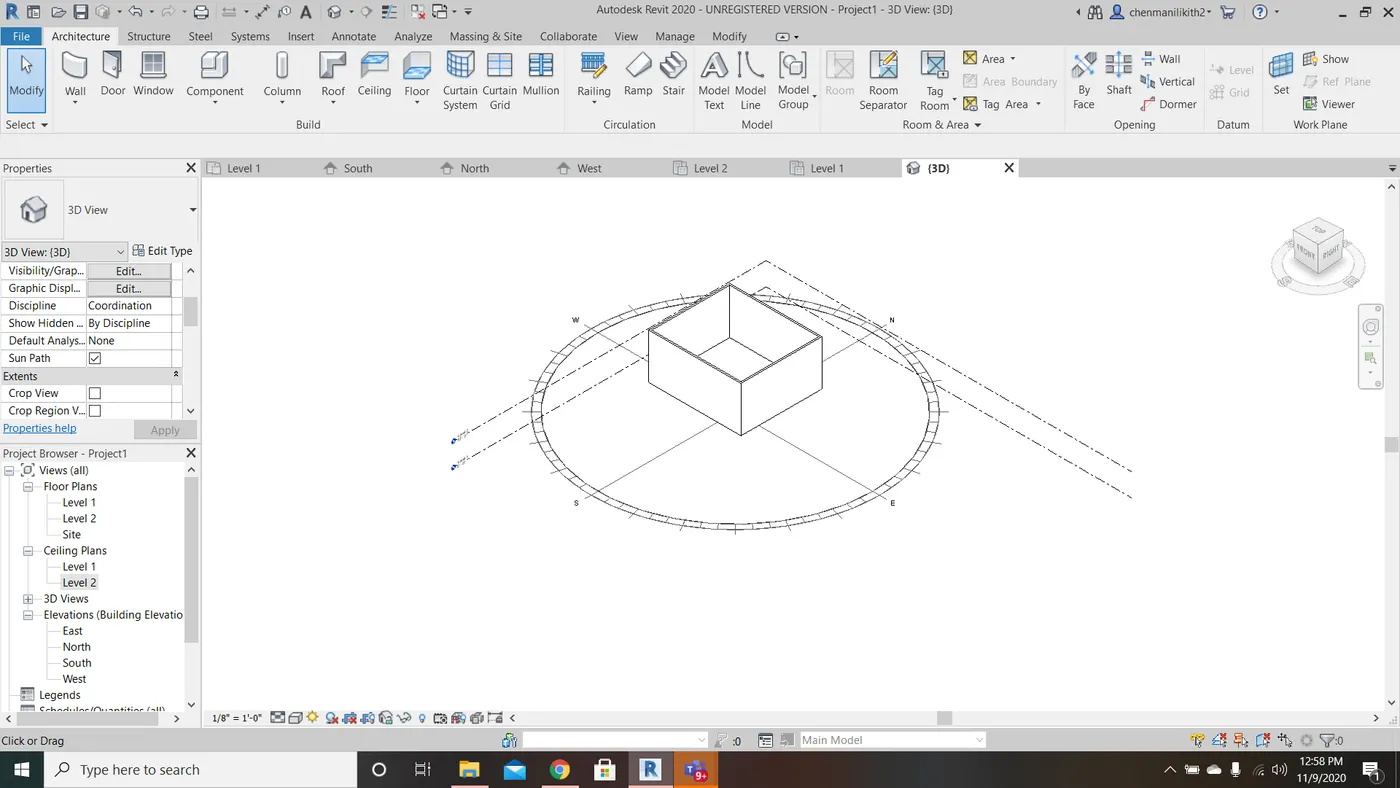
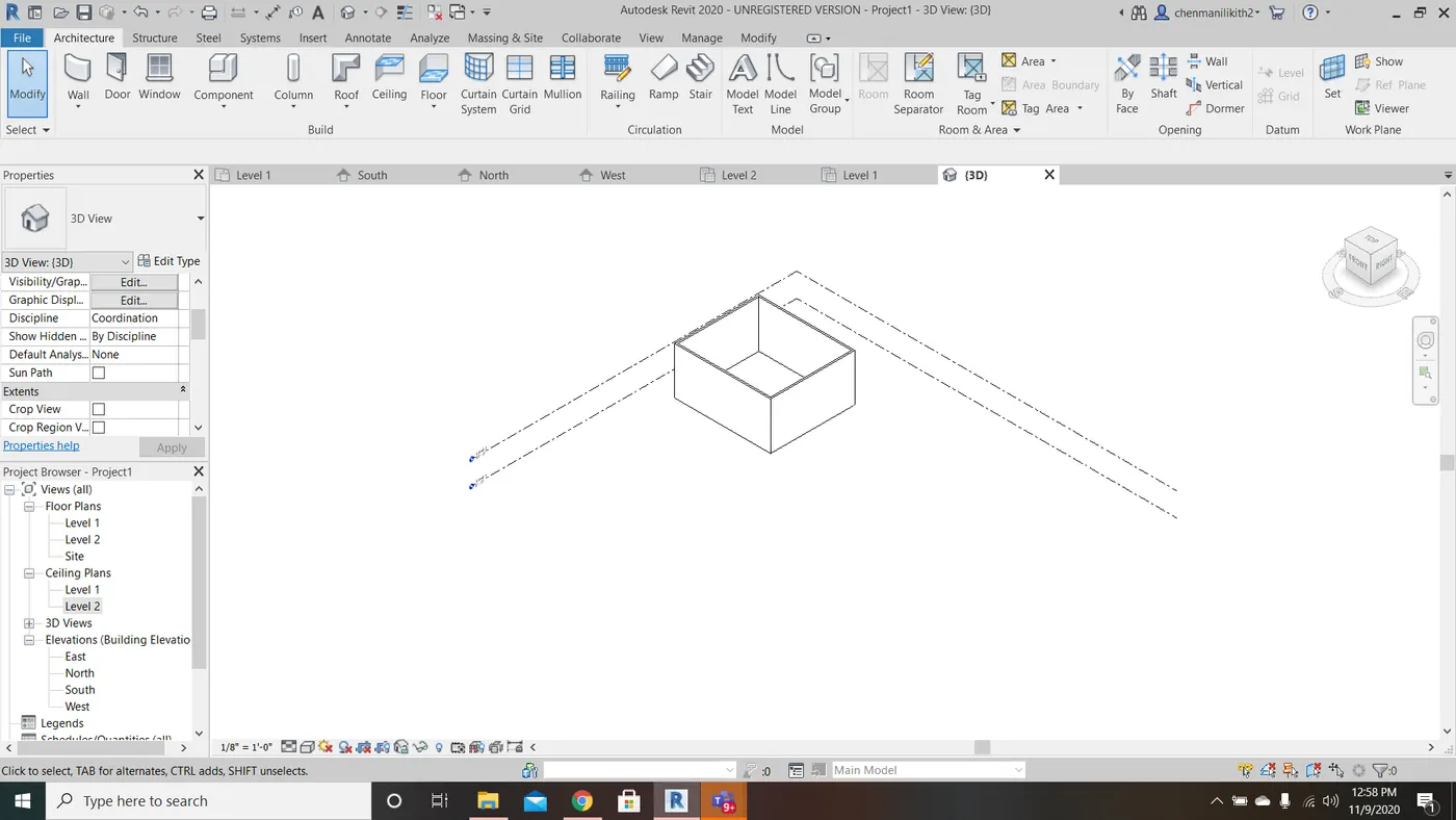
Fig. 1 Fig. 2
10) Use the Manage tool bar to enter project settings, project name and project issue date (choose according to your convenience).
AIM: To enter project settings, project name and project issue date.
TOOLS USED: Manage Tool Bar, project Information Tool
PROCEDURE:
- Select Manage tool bar.
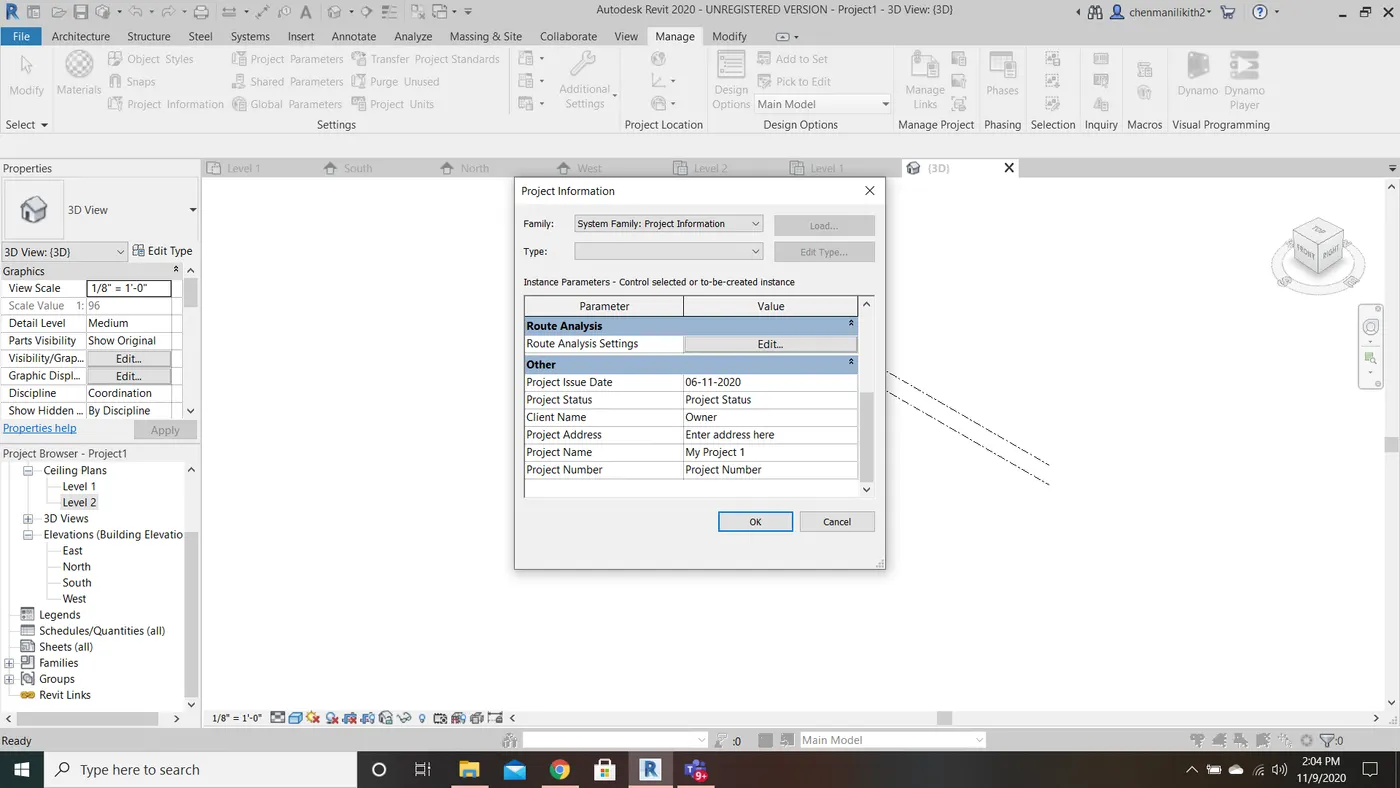
- Click the project information under the settings section in the manage tool bar.
- A dialog box will be appear, now enter the project settings, project name and project issue date.
- In the picture given below the project is named My Project 1, issue date as 06-11-2020 and changed the energy settings and route analysid settings.
11) What is Analyze tool bar used in Revit? How it is beneficial for design and modelling.
Analyze tool bar helps in creating revit models, this tool bar consists of many other options which help in load combinations, boundary conditions, load and cases adjustment and support systems are one amoung the tool under this analyze tool bar where in we get to adjust the model and add aditional support to the present model, it also verifies the analytical and physical model for the consistency.
Space seperation, space naming, space tagging are also the options available assigning the names an numbers the architectural rooms. Colour fill energy optimizations are the tools which help to know how far the present model is eco-friendly and economical.
12) What are the links that Revit supports to be linked to the model?
- Link Revit: Links one revit model to the other or the current revit project.
- Link CAD: links CAD file to the present revit project.
- Link IFC: Links an IFC file to the current project for the information that is requried for additional design work.
- Link Topography: It links the existing topography to the present revit model.
- Link Image: It allows us to link an image for the progressing revit model.
- Manage links: It manages the links such as CAD, mark up the DWF files and all the BIM works that are related to the present file.
- Link PDF: It allows us to link an image for the progressing revit model.
- Coordination Model: It links up a NWD or NWC file to extract content for the revit model.
- DWF Markup: It links the markes up DWF files into the present revit project so that we can see mark-ups in the corresponding sheets.
- Point Cloud: It links a point cloud file to the current revit project.