REVIT_Creation of Basic Drawing_Week 2
1) What is BIM? Summarize the features of BIM and benefits of using BIM over 2D CAD tools.
A) BIM stands for Building Information Modeling. It is a very effective and advanced software which plays a vital role in drafting and planning softwares. BIM is a 3D modelling software which helps us in understanding and explaining about the project. BIM was invoked by autodesk and we can say that autodesk helps us in achieving BIM. BIM is mainly classified into two things :
- Computation
- Coordination
Computation : It is an other advantage of BIM where it mainly involves the calculation and schedule planning.The advantage of computatioin are:
- Material schedule.
- Quantity schedule.
- Energy evaluation.
- Load calculation.
Coordination : It is well developed in BIM because mutliple people can work on the same project simultaneously and it is also time saving. With perfect coordination we can arrange a lot of poeple and increse the efficiency and accuracy.
The benefits of using BIM over 2D CAD tools are:
- With the help of BIM we can achieve complete representaion of the project.
- BIM is real time modeling. We can achieve changes in the whole project by changing at one place.
- We can use links co as to complete the project with higher efficiency and accuracy.
- Improves scheduling.
- BIM is much time saving as compared to 2D CAD.
2) Understand the concept of Categories, Families, Elements, Instances in Revit. Go to Insert Tab, choose a category. Pick a family and element. Understand the instances and insert it to Revit model.
- Family: It is a group of 2D and 3D information which are helpful in designing the project.
- Elements: The elements are controlled and defined by the families.
- Category: Revit family falls into different categories like lighting fixtures, pipe fittings etc.
- Instances: These are the items which will be available after installing the families.
AIM: Go to insert tab and select a category, pick a family and element.
TOOLS USED:
- Insert tab.
- Load family.
- File name.
- Open.
PROCEDURE:
- Open revit and select achitectural template.
- Click on insert menu.
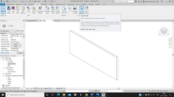
- Select load family.
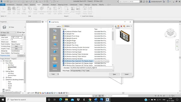
- A load family dialog box appears.
- Select the component from the family dialog box.
- Then click on open.
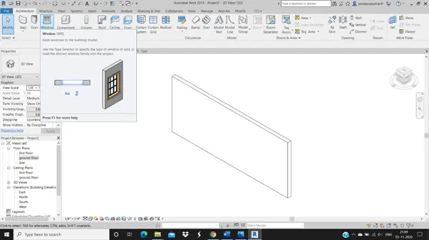
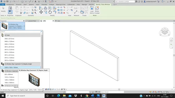
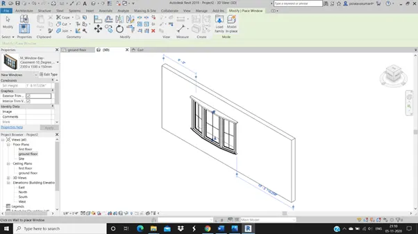
- Go to window in architecture menu and select the object.
- Drag and click where you want to insert the component.
RESULT: With the help of the above steps we can use the families and the components in the project
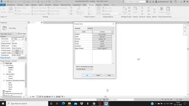
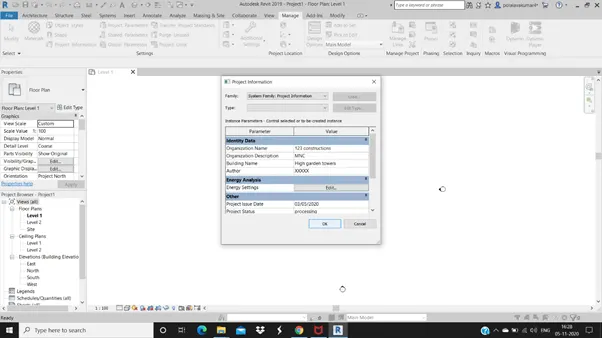
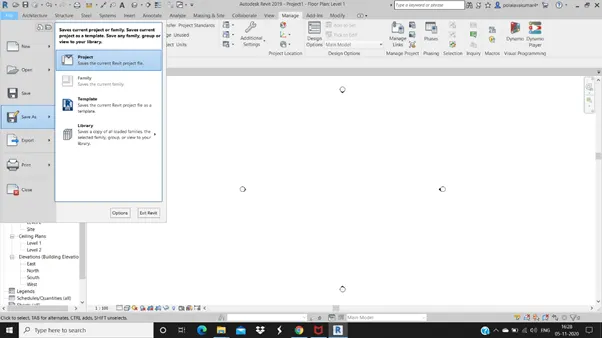
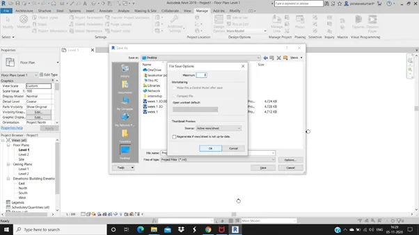
3) Setting up a Project – Open a project file with architectural template. Save the file with appropriate name. Set up the project units to Imperial / Metric based on your convenience of modelling. Complete the project information under Manage tab. Set up the maximum backups for project file to 3
AIM : To open a project file with architectural template. Save the file with appropriate name. Set up the project units. Complete the project information and set up maximum backups for project file to 3.
TOOLS USED :
- Revit 2019.
- New.
- Save as.
- Manage.
- Project units.
PROCEDURE :
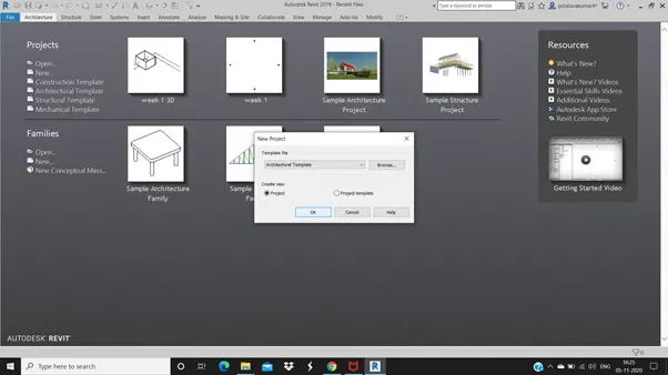
- Open revit 2019, click on new option.
- Select architectural template and click on ok.
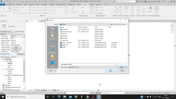
- Click on file menu and select save as option and click on project.
- Save as dialog box appears, give a name to the project and save it.
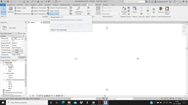
- Click on manage memu and change the project units to imperial/metric
- Click on project information and fill in the details.
- At last set the maximum backups to 3.
RESULT: We can open a project in architectural template and save it with a appropriate name having 3 backups of the project. We can change the project units and fill in the project information with the above steps.
4) Understand the concept of Levels and Grids. Follow the naming and conventions. Create the following Levels: ( Convert to metric equivalents if metric is your units)
Ground Floor @ 0’
First Floor @ 10’
Second Floor @ 20’
Roof @ 30’Grids Transverse Grids A, B,C,D, E @ 10’ spacing
Longitudinal Grids from 1 to 10 @ 20’ spacing
Levels : Levels are used to represent the floors in the elevation.
Grids : Grids are used to represent all the walls with the help of horizontal and vertical lines with the help of notation.
AIM :
To create the following levels:
- ground floor @ 0'.
- first floor @ 10'.
- second floor @ 20'.
- roof @ 30'.
- Transverse grids A,B,C,D,E @ 10' spacing.
- Longitudinal grids 1 to 10 @ 20' spacing
TOOLS USED:
- Architecture.
- Grid.
- Levels.
PROCEDURE:
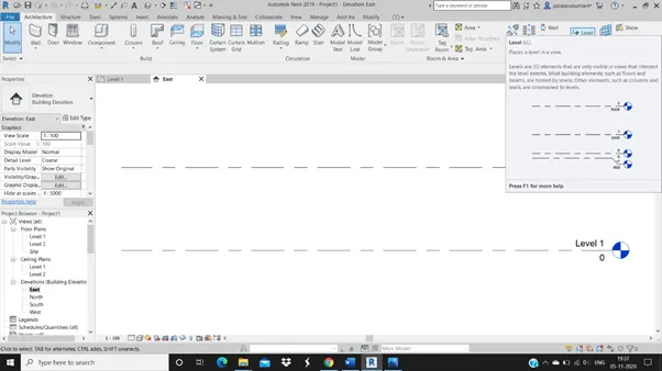
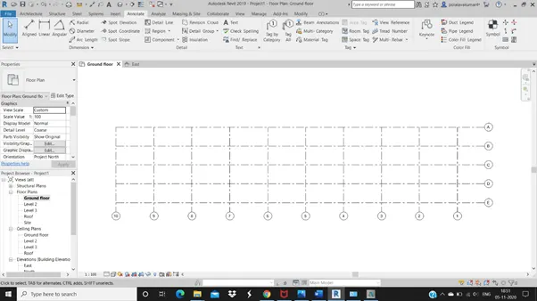
- Firstly select the architectural template and click on east option under elevations.
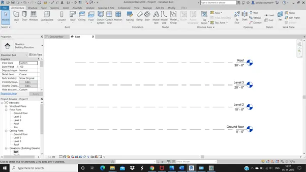
- Then we get the elevation view of the levels, rename the levels and place them at the required distance.
- If required add new levels for the roof by using the level option in the arctitecture menu.
- Then select ground floor under floor plans.
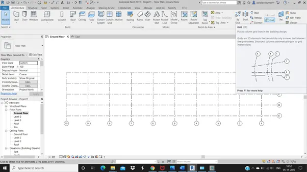
- Select grid option under the architecture menu and start drawing grids.
- Firstly draw 5 horizontal grid lines and name them A,B,C,D and E providing equal spacing of 10'.
- Then draw the vertical grid linesand name them 1-10 providing equal spacing of 20'.
RESULT: At last we get the levels representing ground floor, first floor, second floor and roof at the heights at 0',10',20' and 30'. As well as the grid of horizontal and vertical grid lines.
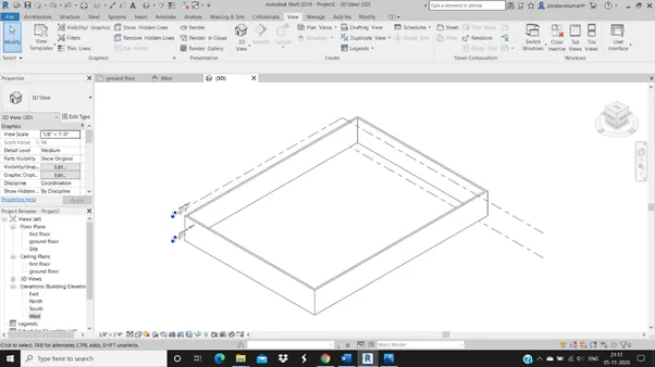
5) 3D modelling of residential unit – From looking at your house / or a place you aspire. Create a conceptual layout of the residential unit. You can measure using a tape or
you can access your residential plan to create a similar layout.
AIM: 3D modeling of a residential house, to create a conceptual layout of the residential unit.
TOOLS USED:
- Architecture.
- Wall.
- View.
- Default 3D view.
PROCEDURE:
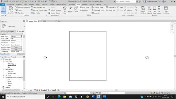
- Open revit and select architectural template and click on ok.
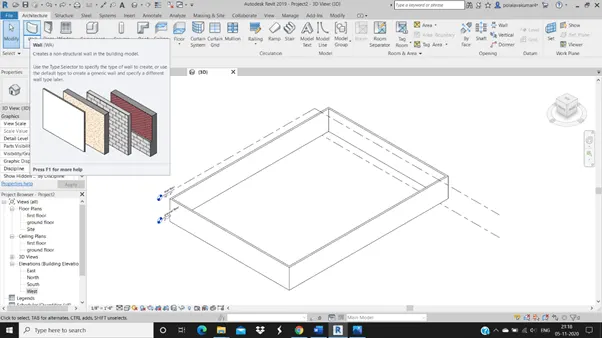
- Select wall tool from architecture menu and click the curson on the drawing space where you want to start your project.
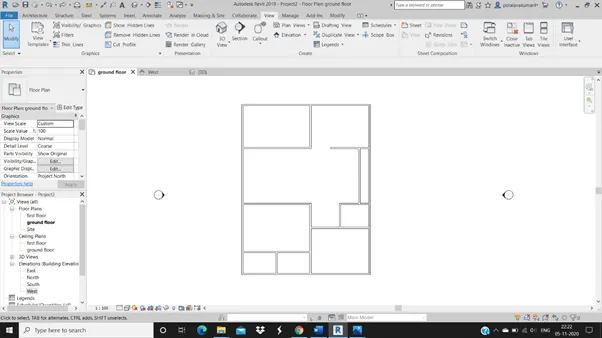
- After drawing one side repeat the same process for the remaining sides with the desired dimensions.
- At last we can join the end of the fourth side to the starting point so as to obtain a closed figure.
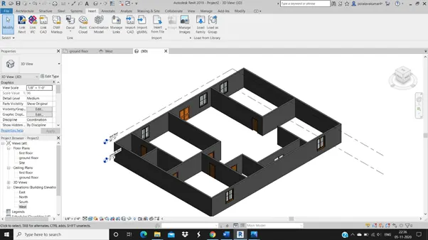
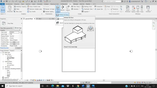
- Next click on the view menu and select the Default 3D view option.
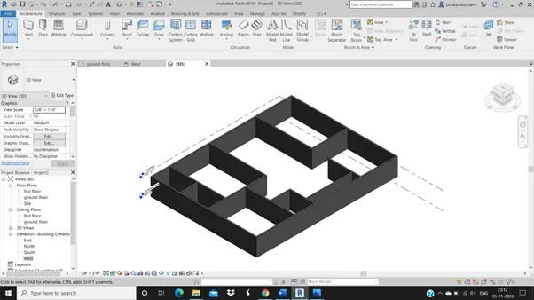
- The required layout appears in 3D view.
RESULT: Thus by following the above mentioned steps we can draw the required layout in 3D view.
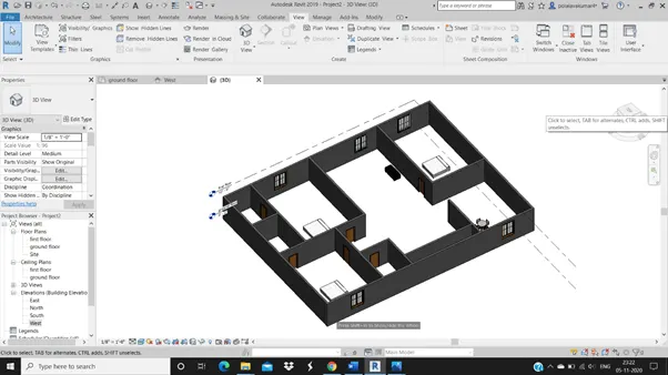
6) In the layout created draft the level of details you are planning to include – Dimensions of room, components you plan to add in the residential unit.
AIM: In the layout created draft the level of details you are planning to include i.e Dimension of room, add components to the residential unit.
TOOLS USED :
- Insert.
- Load family
- Architecture
- Window
- Door
- View
- Default 3D view
PROCEDURE :
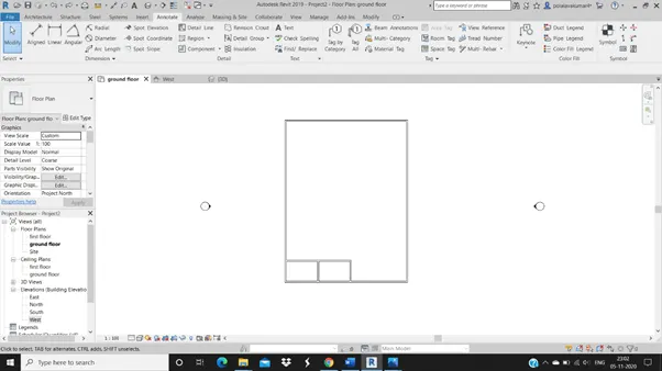
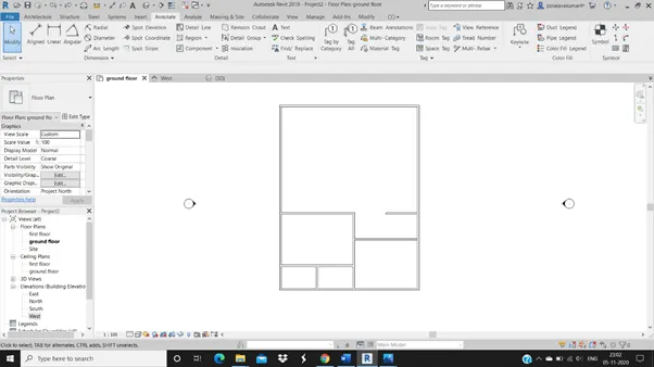
- After completion of the layout with all the four sides with walls.
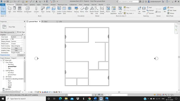
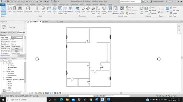
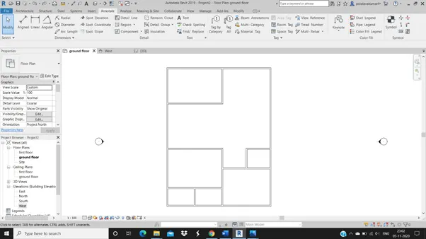
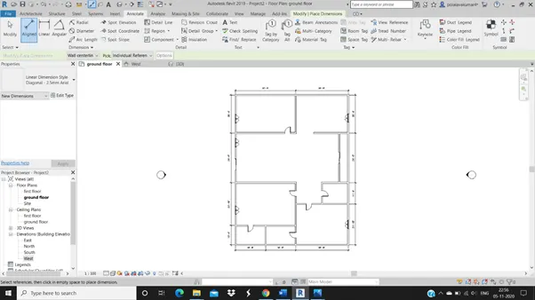
- Then with the help of wall tool from architectural menu draw the remaining inner walls in the layout.
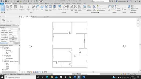
- Click on insert menu and select load family to add components.
- From annotate menu select aligned option to mark the dimensions.
- Then click on view menu option and select default 3D view to convert the project into 3D view.
- At last the ruquired 3D view of the project layout with the components is avaliable.
RESULT: With the above steps we can give details to the layout of the residential building and mark the dimension and convert to 3D view using default 3D view from view menu.
7) Identify the residential model elements such as Door, Windows, Tables, Chair, Couch, Bed, Lamps from the library and insert them to the model . Save the project for use
for Assignment 3
AIM:To add components to the layout project like doors, windows, tables, chairs, couch, bed, lamps from the insert library.
TOOLS USED :
- Insert.
- Load family.
- View.
- Architecture.
- Doors.
- Windows.
- Components.
- Bed.
- Dining table.
PROCEDURE:
- After we complete the inner walls and dimensioning we have to start with the interiour components.
- From insert menu with the help of load family we have to load the components like windows, doors and other componets like table, sofa, beds ets.
- With the help of default 3D view option from the view menun we can convert the project into 3D view.
RESULT: With the above steps we can successfully add the components to the project like doors, windows and other components.