Week 1 Challenge
- Open the STAAD pro software and locate the share option available on the introduction screen.
- After clicking on the share button, select send mail option.
- Then, browse for the. Std file on your machine & send it.
2.) Designs may include any building structures like tunnels, culverts, bridges, piles, and petrochemical plants; and building materials like timber, concrete, steel, cold-formed steel, and aluminum. STAAD or STAAD.Pro was developed by Research Engineers International at Yorba Linda, CA in 1997.
3) YES, it is possible to capture images in STAAD Pro. We can take pictures of models and structural results in staad pro using the take picture command, the command is available in the utility panel with a camera logo.
- Using the STAAD.Pro Physical Modeler interface,
- using the traditional STAAD.Pro analytical modeling interface,
- and using the command file.
5)
|
Select the members which all have the same section. |
1. Add the profile you want to use from the Section Database. |
| 2. Select the Section tool in the Assign properties group on the Member ribbon tab. | 2. Select the member property in the Properties dialog. |
| 3. Select the profile to use and click OK. | 3. Use the cursor to click on members with this property. |
2.1) Target Compressive strength, fck; Reinforcement Steel grade, fy; Cover; Depth; Minimum and maximum Reinforcements; Bar Diameter.
2.2) Nodes Cursor, Beams Cursor, Plates Cursor, Solids Cursor.
3)
- On the View ribbon tab, select the Front View tool in the Tools group.

The view rotates to this angle. - Click-and-drag the mouse pointer from the top-left towards the bottom-right of the slab members.
Note: You may need to select the Beam Cursor tool on the Select ribbon tab first.

- On the View ribbon tab, select the New View tool in the Views group.

The New View dialog opens.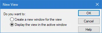
- Select the Display the view in the active window option and then click OK. The new view is displayed in the active view window. Only the selected slab members are currently displayed. The wall members are still contained in the model. They are just hidden from this view.
- On the View ribbon tab, select the Isometric View tool in the Tools group.
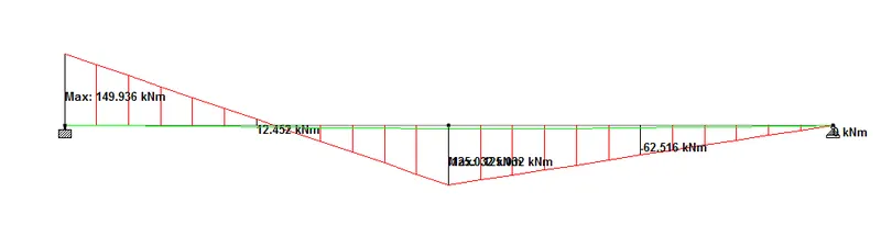
4) Create two nodes using the Grid / Coordinates option. Now the two nodes denote the end of beams. Select the nodes using Nodes Cursor and go to Supports - Create Pinned for both nodes to make it act like SS beam.
- Name of the project and the location of the project.
- Structural Layout.
- Introduction to the construction methodology.
- Quality Assurance and Quality Control.
- Budget of the Project.
6) The term "Multi-material design" of STAAD Pro defines the structure that is designed by implementing more than one structural material.
3.1) STAAD Pro is one of the popular software that is used for analyzing & designing structures like – buildings, towers, bridges, industrial, transportation, and utility structures.
3.2) This coordinate system is a rectangular coordinate system (X, Y, Z) which follows the orthogonal "right hand" rule. This coordinate system may be used to define the joint locations and loading directions.
3.3) A DBR tool creates a schedule, and a series of priority management systems (Buffers and Ropes) that ensure the bottleneck is always working at full capacity—which means that your shop is always working at full capacity—translating into more jobs completed and out the door on time.
3.4) It can make use of various forms of analysis from the traditional static analysis to more recent analysis methods like p-delta analysis, geometric non-linear analysis, Pushover analysis (Static-Non Linear Analysis) or a buckling analysis.
3.5) When the FIXED or FIXED BUT type of support is specified, for those degrees of freedom which are to be treated as fully restrained, STAAD assumes the displacements to be known quantities whose value is zero. Hence, those degrees of freedom are not considered for the stiffness matrix, and their value is not calculated. (For the FIXED BUT support type, if any degrees of freedom are assigned a spring using the KFX thru KMZ terms, those are treated as unknowns and their displacements are calculated).
When the ENFORCED or ENFORCED BUT type of support is specified, for those degrees of freedom which are to be treated as restrained, STAAD assigns a spring with a very high spring stiffness - translational stiff springs for translational restraints, and rotational stiff springs for rotational restraints. Those degrees of freedom which are free to displace are assigned springs of zero stiffness. Hence, for all the 6 degrees of freedom at such supports, the displacements are calculated. The ones which have a stiff spring will end up having a negligible displacement, and those with zero-stiffness-springs will have a displacement based on the structure geometry, properties and loading.
The following are some of the ramifications of using the two support types.
1) Even though the two types follow different approaches, the end result - joint displacements, member forces and support reactions - should be the same.
2) Since the number of unknowns is less in the former method compared to the latter, the time required to compute the results will also be comparatively less using the first method. If the model is large, there may be a significant reduction in time required to perform the analysis.
3) For supports directly attached to plates or solids, if the supports are subjected to artificial displacements (called sinking support or support settlements), the effects caused by such displacements can be computed only if the ENFORCED type of support is used. In STAAD, support displacement loads cannot be applied to such models when the FIXED type of support is specified.
4) For the ENFORCED BUT type, there is no provision to specify a spring constant. The only choices, which are built into the program, are - zero stiffness or very high stiffness. So, if a user plans to assign his/her own spring constant, the FIXED BUT type is the only choice.
5) If the engineer plans to analyze a model in which support conditions change depending on the loading condition (hence he/she specifies the support command multiple times in the model), there are a few restrictions on how the supports must be assigned.