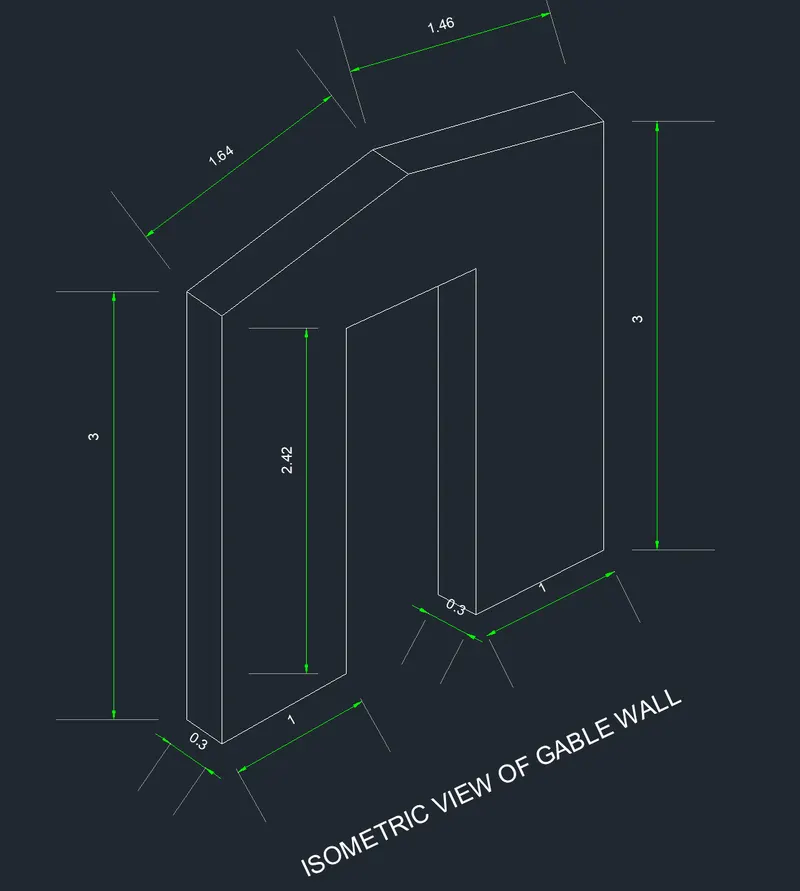
Creating a Floor plan, Footing detail and Isometric view using AutoCad
1. I have created this drawing using the line command.
Step 1: Type (L) for the Line command.
Step 2: Press Enter.
Step 3: Measure linear dimensions using DIMLINEAR.
Step 4: Type DIM.
Step 5: Press Enter.
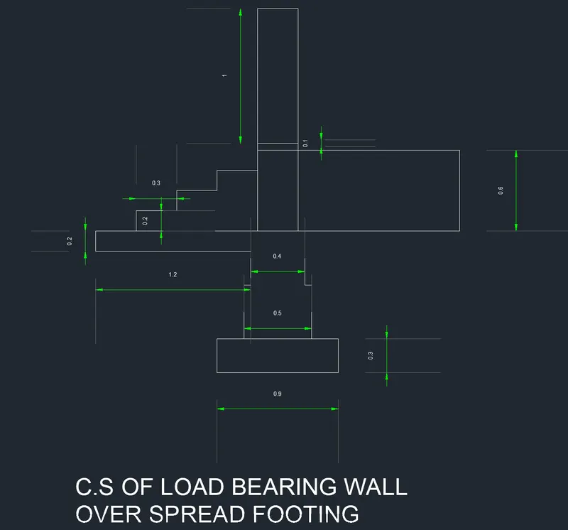
2. I have created this drawing using the line command.
Step 1: Type (L) for the Line command.
Step 2: Press Enter.
Step 3: Measure dimensions using DIMLINEAR.
Step 4: Type DIM.
Step 5: Press Enter.
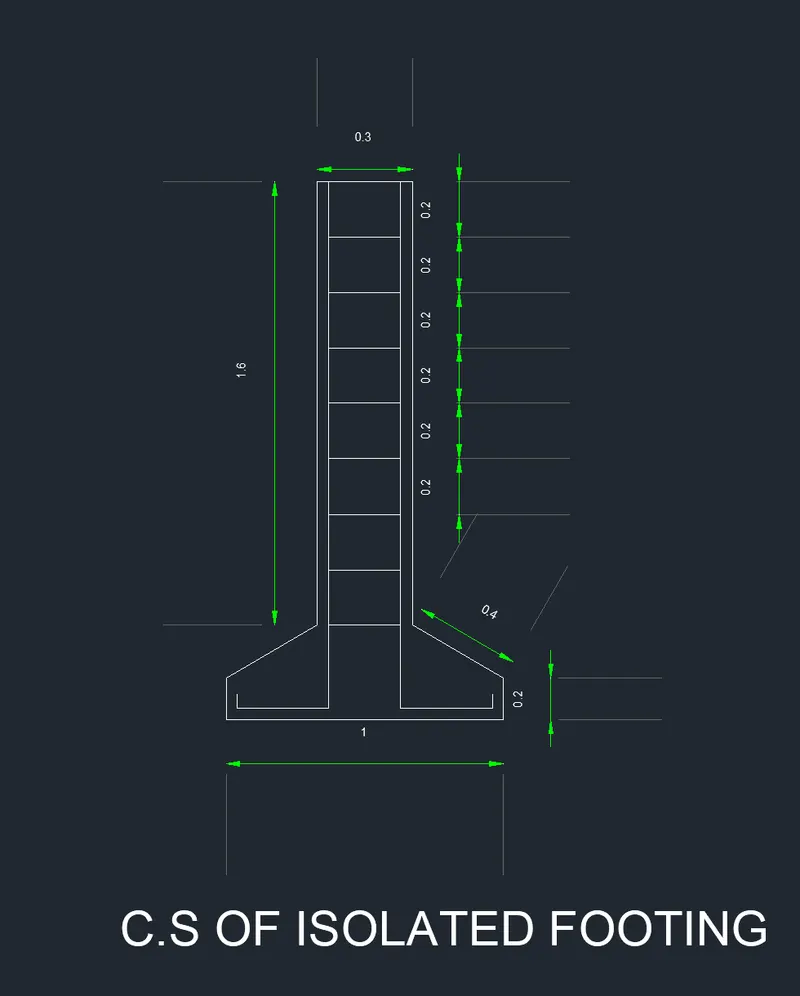
3. I have created this drawing using the line command.
Step 1: Type (L) for the Line command.
Step 2: Press Enter.
Step 3: Measure dimensions using DIMLINEAR.
Step 4: Type DIM.
Step 5: Press Enter.
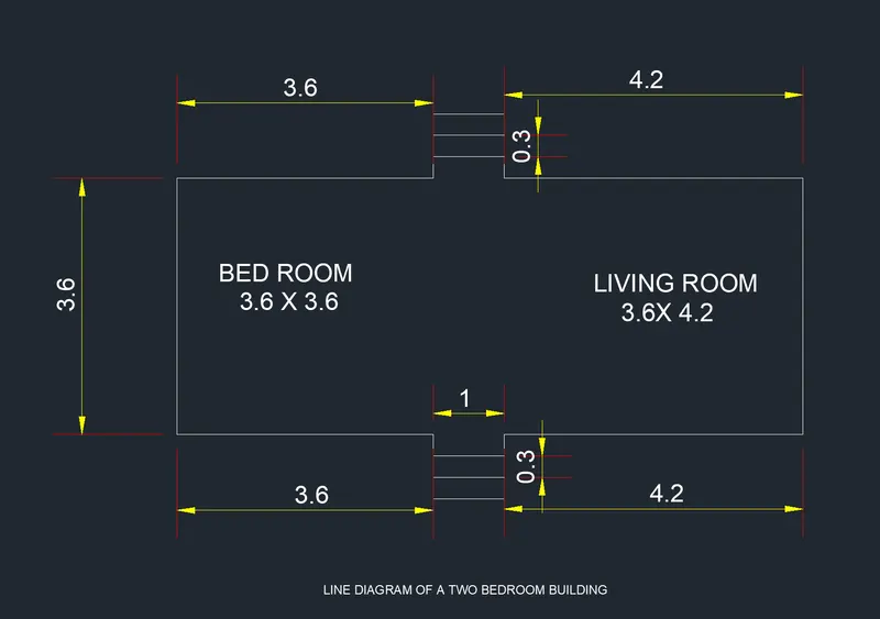
4. I have created this drawing using the line command.
Step 1: Type (L) for the Line command.
Step 2: Press Enter.
Step 3: Measure dimensions using DIMLINEAR.
Step 4: Type DIM.
Step 5: Press Enter.
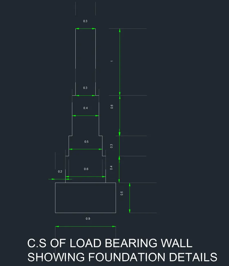
5. I have created this Isometric view of steps using the SNAPSTYL command.
Step 1: Type (SNAPSTYL) for the ISOMETRIC View.
Step 2: Press Enter.
Step 3: Type 1.
Step 4: Press Enter.
Step 5: Take 1.00 meters in X direction for length of tread .
Step 6: Take 0.3 mm Z direction for width of tread.
Step 7: Take 0.15 mm in Y direction for riser height.
Step 8: Measure dimensions using DIMLINEAR.
Step 9: Type DIM.
Step 10: Press Enter.
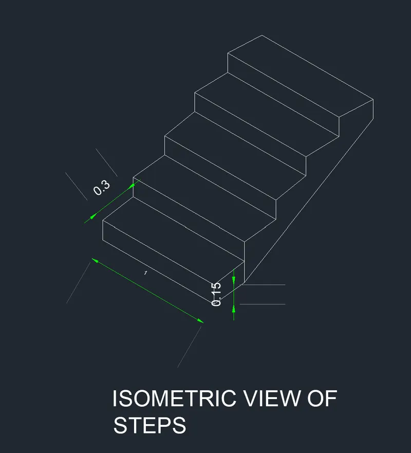
6. I have created this drawing using the line command.
Step 1: Type (L) for the Line command.
Step 2: Press Enter.
Step 3: Measure dimensions using DIMLINEAR.
Step 4: Type DIM.
Step 5: Press Enter.